Installation and operation of overhead power lines. Reinforced concrete poles of power lines Designation of power line poles in the drawing
Read also
Reinforced concrete poles for power lines used in assembly overhead lines power transmission lines (VL and VLI) in settlements and in uninhabited areas. Reinforced concrete supports are made on the basis of standard concrete pillars: SV 95-2V, SV 95-3V, SV110-1A, SV 110-3.5A, SV110-5A.
Reinforced concrete power transmission line poles - classification by purpose
The classification of reinforced concrete poles according to their purpose does not go beyond the types of poles standardized in GOST and SNiP. Read in detail: Types of supports for their intended purpose, but here I will briefly remind you.
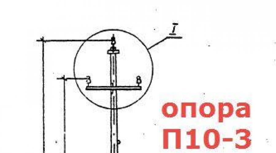
Intermediate concrete supports needed to support cables and wires. They are not loaded with longitudinal or angular tension. (marking P10-3, P10-4)

Anchor concrete supports provide retention of wires during their longitudinal tension. Anchor supports must be placed at the intersection of power lines with railways and other natural and engineering barriers.
Angle supports are placed on the turns of the power line route. At small angles (up to 30 °), where the tension load is not large and if there is no change in the cross section of the wires, angular intermediate supports (UP) are placed. At large angles of rotation (more than 30 °), angular anchor supports (UA) are placed. Anchor end supports (A) are placed at the end of the power line. For branches to subscribers, branch anchor supports (OA) are installed.


Marking of concrete supports
It is worth stopping at the marking of the supports. In the previous paragraph, I used the markings for the supports 10-2. I will explain how to read the markings of the supports. Reinforced concrete supports are marked as follows.
- The first two letters indicate the purpose of the support: P (intermediate) UE (angular intermediate), UA (corner anchor), A (anchor-end), OA (branch support), UOA (angular branch anchor).
- The second digit means for which power line the support is intended: the number "10" is a 10 kV power line.
- The third digit after the dash is the size of the support. The number "1" is a support of 10.5 meters, based on the pillar SV-105. The number "2" is a support based on the pillar SV-110. Detailed sizes in the tables at the bottom of the article.
Structures of reinforced concrete supports
Reinforced concrete support structures also do not go beyond standard support structures.
- Guyed portal supports - two parallel supports are held on guy cables;
- Free-standing portal supports with crossbars;
- Free-standing supports;
- Supports with braces.
The use of supports must comply with design calculations. For calculations, various normative tables are used, the volume of which occupies several volumes.
Concrete supports by number of chains held
If the crossbars of the support allow only one EP line to be hooked, it is called single-chain (crossbar on one side). If the crossbar is on both sides, then the support is double-chain. If you can hang many lines of wires, then this is a multi-chain support.
class="eliadunit">
Installation of concrete supports
The calculation of supports is carried out by SNiP 2.02.01-83 and "Guidelines for the design of power lines and foundations of power lines ...". The calculation is based on deformation and bearing capacity.
To fix intermediate support type P10-3 (4) it is necessary to drill a cylindrical pit with a diameter of 35-40 cm, to a depth of 2000-25000 mm. An installation bolt on such a support is not needed.
Anchor Angle and Anchor Branch Supports, are usually mounted with mounting bolts. I would like to draw your attention to the fact that crossbars can be placed on the lower edge of the support and strut buried in the ground and / or on the upper edge of the support, along the top of the pit. Crossbars provide additional stability of the support. The depth of digging the support depends on the freezing of the soil. Usually 2000-2500 mm.
Grounding of concrete supports
Thanks to the design of the poles, grounding the poles is very convenient. In the racks of the SV supports, in the factory during their manufacture, the top and bottom of the rack is displayed metal fittings 10 mm in diameter. This reinforcement goes inextricably along the entire length of the rack. It is this reinforcement that serves to ground reinforced concrete supports.
Designation of overhead line supports
Designation of supports.
For supports of overhead lines of 35 kV and above, as a rule, the following notation is used. The number in front letter designation indicates the number of posts that make up the support. If the letter B is present in the designation of the support, this indicates that the support is reinforced concrete, D - wooden, M - multifaceted metal, the absence of these letters means that the support is a metal lattice type. In addition, the designation of the supports includes letters indicating the type of supports (see the table below). The numbers 35, 110, 150, 220, etc., following the letters, indicate the voltage of the overhead line, and the number following them after the hyphen indicates the size of the supports (odd - for single-circuit and even - for double-circuit supports). If the letter T is followed by the standard size of the support, this means that the support has a cable rack. The numbers after the standard size of the support after the hyphen or the “+” sign indicate the size of the additional stand section.
Table - Designation of supports
| Designation | Decryption |
| P | Intermediate support. |
| To | End support. |
| BUT | Anchor support. |
| O | Branch support. |
| FROM | Special support. For example, US110-3 stands for: metal anchor-angle single-circuit special (with horizontal wires) support for 110 kV overhead lines; US110-5 stands for: metal anchor-angle single-circuit special (for urban development - with a reduced base and increased suspension height) support for 110 kV overhead lines. |
| At | Angle support. For example, U110-2 + 14 stands for: metal anchor-angle double-circuit support with a stand 14 m high for 110 kV overhead lines. |
| P | Transition support. For example, PPM110-2 is deciphered as follows: an intermediate metal multifaceted double-circuit transitional support for a 110 kV overhead line. |
| B | Reinforced concrete support. For example, PB110-1T is deciphered as follows: an intermediate single-circuit single-column reinforced concrete support with a cable-resistant for 110 kV overhead lines. |
| M | Multifaceted support. For example, PM220-1 stands for: intermediate metal multifaceted single-circuit support for 220 kV overhead lines. |
| D | Wooden support. For example, UD220-1 stands for: wooden anchor-angle single-circuit support for 220 kV overhead lines. |
| T | Rope-resistant support. For example, U35-2T + 5 stands for: a metal anchor-angle double-circuit support with a cable-resistant and a stand 5 m high for a 35 kV overhead line. |
| AT | Support with internal connections. For example, 2PM500-1V is deciphered as follows: an intermediate metal multifaceted single-circuit support with internal connections for a 500 kV overhead line, consisting of two racks. |
Depending on the method of suspension of wires, the supports of overhead lines (VL) are divided into two main groups:
a) intermediate supports, on which the wires are fixed in supporting clamps,
b) anchor type supports used to tension the wires. On these supports, the wires are fixed in tension clamps.
The distance between the supports (power lines) is called the span, and the distance between the anchor type supports is anchored section(Fig. 1).
In accordance with the intersection of some engineering structures, such as public railways, it is necessary to perform on anchor-type supports. At the corners of the line, corner supports are installed, on which the wires can be suspended in support or tension clamps. Thus, the two main groups of supports - intermediate and anchor - are divided into types that have a special purpose.
Rice. 1. Scheme of the anchored section of the overhead line
Intermediate straight supports are installed on straight sections of the line. On intermediate supports with suspension insulators, the wires are fixed in supporting garlands hanging vertically; on intermediate supports with pin insulators, the wires are fixed by wire knitting. In both cases, intermediate supports perceive horizontal loads from wind pressure on the wires and on the support, and vertical - from the weight of wires, insulators and the own weight of the support.
With unbroken wires and cables, intermediate supports, as a rule, do not perceive the horizontal load from the tension of wires and cables in the direction of the line and therefore can be made more light construction than supports of other types, for example, end supports that perceive the tension of wires and cables. However, to ensure reliable operation line intermediate supports must withstand some load in the direction of the line.
Intermediate corner supports installed at the corners of the line with a suspension of wires in supporting garlands. In addition to the loads acting on the intermediate straight supports, the intermediate and anchor angle supports also perceive loads from the transverse components of the tension of the wires and cables.
At angles of rotation of the power line of more than 20 °, the weight of the intermediate corner supports increases significantly. Therefore, intermediate corner supports are used for angles up to 10 - 20°. At large angles of rotation, anchor angle supports.
Rice. 2. Intermediate supports VL
Anchor supports. On lines with suspension insulators, the wires are fixed in the clamps of the tension garlands. These garlands are, as it were, a continuation of the wire and transfer its tension to the support. On lines with pin insulators, the wires are fixed on anchor supports with reinforced viscous or special clamps that ensure the transfer of the full tension of the wire to the support through the pin insulators.
When installing anchor supports on straight sections of the route and suspending wires on both sides of the support with the same tensions, the horizontal longitudinal loads from the wires are balanced and the anchor support works in the same way as the intermediate one, i.e. it perceives only horizontal transverse and vertical loads.
Rice. 3. Anchor-type overhead line supports
If necessary, the wires on one and the other side of the anchor support can be pulled with different tension, then the anchor support will perceive the difference in tension of the wires. In this case, in addition to horizontal transverse and vertical loads, the horizontal longitudinal load will also act on the support. When installing anchor supports at the corners (at the turning points of the line), the anchor corner supports also perceive the load from the transverse components of the tension of the wires and cables.
End supports are installed at the ends of the line. From these supports depart wires suspended on the portals of substations. When hanging wires on the line until the end of the construction of the substation, the end supports perceive full one-sided tension.
In addition to the listed types of supports, special supports are also used on the lines: transpositional, serving to change the order of the wires on the supports, branch - to carry out branches from the main line, support for large crossings over rivers and water spaces, etc.
The main type of supports on overhead lines are intermediate ones, the number of which is usually 85 -90% total number supports.
According to the design of the support can be divided into free-standing and braced supports. Guys are usually made of steel cables. On overhead lines, wooden, steel and reinforced concrete supports are used. Designs of supports made of aluminum alloys have also been developed.
Structures of overhead lines
- Wooden support LOP 6 kV (Fig. 4) - single-column, intermediate. It is made of pine, sometimes larch. The stepson is made of impregnated pine. For 35-110 kV lines, wooden U-shaped two-column supports are used. Additional elements support structures: hanging garland with hanging clip, traverse, braces.
- Reinforced concrete supports are made as single-column free-standing, without braces or with braces to the ground. The support consists of a post (trunk) made of centrifuged reinforced concrete, a traverse, a lightning protection cable with a ground electrode on each support (for lightning protection of the line). With the help of a grounding pin, the cable is connected to a grounding conductor (a conductor in the form of a pipe hammered into the ground next to the support). The cable serves to protect the lines from direct lightning strikes. Other elements: rack (trunk), traction, traverse, cable rack.
- Metal (steel) supports (Fig. 5) are used at a voltage of 220 kV or more.
Types and designations of supports
Supports made of various materials can be used on overhead lines.
For VL should be used the following types supports:
1) intermediate, installed on straight sections of the overhead line route. These supports in normal operating modes should not perceive the forces directed along the overhead line;
2) anchor, installed to limit the anchor span, as well as in places where the number, grades and cross sections of overhead lines change. These supports should perceive, in normal operating modes, the forces from the difference in the tension of the wires directed along the overhead line;
3) angular, installed in places where the direction of the overhead line changes direction. These supports, under normal operating conditions, must perceive the resulting load from the tension of the wires of adjacent spans. Corner supports can be intermediate and anchor type;
4) terminal, installed at the beginning and end of the overhead line, as well as in places limiting cable inserts. They are anchor-type supports and must perceive, in normal operating modes of overhead lines, the one-sided tension of all wires.
Depending on the number of chains suspended on them, the supports are divided into single-chain, double-chain and multi-chain.
Supports can be free-standing or with braces.
Intermediate supports can be of flexible and rigid construction; anchor supports must be rigid. It is allowed to use anchor supports of a flexible design for overhead lines up to 35 kV.
Supports on which branches from overhead lines are carried out are called branch; supports on which the crossing of overhead lines is carried out different directions or intersection of overhead lines with engineering structures, - cross. These supports can be of all the above types.
Support structures should provide the ability to install:
- lamps street lighting all types;
- end cable couplings;
- protective devices;
- sectioning and switching devices;
- cabinets and shields for connecting electrical reception.
Support types
P - intermediate;
PP - transitional intermediate:
UE - angular intermediate:
A - anchor;
PA - transitional anchor;
AK - anchor end:
K - terminal:
UA - corner anchor;
PUA - transitional corner anchor;
AO - anchor branch;
POA - transitional anchor branch;
Oh - branch.
Nomenclature of reinforced concrete supports for 10 kV transmission lines
Support code |
Number of racks per support |
Rack code |
Rack height, m |
Height to the lower traverse, m |
Volume of reinforced concrete, m |
Mass of metal structures, kg |
CB105-3.5; CB105 CB105-3.5; CB105 CB105-3.5; CB105 CB105-3.5; CB105 CB105-3.5; CB105 CB105-3.5; CB105 CB105-3.5; CB105 CB105-3.5; CB105 CB105-3.5; CB105 CB105-3.5; CB105 CB105-3.5; CB105 CB105-3.5; CB105 CB105-3.5; CB105 CB105-3.5; CB105 CB105-3.5; CB105 CB105-3.5; CB105 CB105-3.5; CB105 CB105-3.5; CB105 CB105-3.5; CB105 CB105-3.5; CB105 CB105-3.5; CB105 CB105-3.5; CB105 CB105-3.5; CB105 CB105-3.5; CB105 CB105-3.5; CB105 CB105-3.5; CB105 CB105-3.5; CB105 CB105-3.5; CB105 CB105-3.5; CB105 CB105-3.5; CB105 CB105-3.5; CB105 CB105-3.5; CB105 |
MINISTRY OF EDUCATION AND SCIENCE OF THE RUSSIAN FEDERATION
Federal State Budgetary Educational Institution of Higher Professional Education
Kazan State University of Architecture and Civil Engineering
Department of Geodesy
SELECTED SYMBOLS
Guidelines
To perform settlement and graphic work by students studying in the direction of "Construction".
Kazan-2012
Compiled by: V.S. Borovskikh, M.G. Ishmukhametova
Selected symbols. Guidelines for the performance of settlement and graphic work by students of the 1st year of full-time education in the direction of "Construction". Methodological instructions correspond to the State General Educational Standard.
Kazan State University of Architecture and Civil Engineering.
Comp.: V.S.Borovskikh, M.G.Ishmukhametova
Kazan, 2012 - 17 p.
ill. 90, table 1
Reviewer: SNS, Associate Professor, PhD, Department of Astronomy, Kazan State University M.I. Shpekin
C Kazan State University of Architecture and Civil Engineering
In "Selected Conventional Signs for Topographic Plans at Scales 1:500 and 1:1000" ", the conventional signs of the most common contours and objects of the area are given. They need to be learned and known by students studying at the university. "Selected Conventional Signs" are used when performing calculation graphic work and during summer geodetic practice for drawing plans for theodolite, tacheometric surveys, leveling by squares.
To draw topographic plans and maps of smaller scales, conventional signs are used, as a rule, similar in appearance to conventional signs for scales of 1:500 - 1:1000.
In the "Selected Conventional Signs" in the first column are serial numbers. Symbols are selected from the official publication "Symbols for topographic plans at scales 1:5000, 1:2000, 1:1000, 1:500" - M.: Nedra, 2002, approved by the GUGK of Russia. The second column contains the names of conventional signs and explanations for them, and the third - the image of various signs and their sizes. When drawing plans, the dimensions of the symbols must be observed, but not shown.
When drawing off-scale symbols, images of objects should be placed perpendicular to the southern frame of the plan.
The position of the object on the ground must correspond to the following points of the off-scale sign on the plan:
a) for signs of the correct form (circle, square, etc.) - the center of the sign;
b) for signs with a right angle at the base - the top of the corner;
c) for signs in the form of a perspective image of an object - the middle of the base of the sign.
To draw conventional signs on plans and maps, ink and watercolors of different colors are used. The colors are shown in the explanations of the symbols. If there are no such explanations, the symbols are depicted in black ink.
SELECTED SYMBOLS
for topographic plans
scales 1:1000, 1:500
|
Name and characteristics of a topographic object |
Symbol of a topographic object |
|
|
Points of the state geodetic network |
||
|
Points of the state geodetic network on the mounds |
|
|
|
Points of the state geodetic network on buildings |
|
|
|
Points of geodetic thickening networks and their numbers |
||
|
Leveling benchmarks and their numbers |
|
|
|
Leveling benchmarks and wall marks |
|
|
|
Leveling benchmarks ground construction long-term |
|
|
|
Temporary leveling benchmarks |
|
|
|
Intersections of coordinate lines ( in green) |
||
|
buildings: Residential fire-resistant: (brick, stone, concrete) 1) single deck; 2) above one floor |
||
|
Non-residential fire-resistant buildings: (brick, stone, concrete) 1) single deck; 2) above one floor |
||
|
Non-fire-resistant residential buildings: (wooden, adobe, etc.) 1) single deck; 2) above one floor |
||
|
Non-residential non-fire-resistant buildings (wooden, adobe, etc.) 1) single deck; 2) above one floor |
||
|
Buildings under construction |
||
|
Buildings destroyed and dilapidated |
||
|
Marking the height of the floor of the first floor (inside the contour); Ground mark on the corner of the house |
||
|
1) stone with domes of different heights; 2) wooden with one dome |
||
|
1) stone; 2) wooden |
1)2) |
|
|
Small buildings: 1) individual garages; 2) toilets |
||
|
slopes: Unfortified (number 2,5 - slope height in meters) |
||
|
Unreinforced slopes (figure 102,5 - slope height in meters) |
||
|
Reinforced slopes (number 102,5 - slope height in meters; inscription - a way to strengthen) |
|
|
|
Open pit mining of solid minerals (quarries, etc. (figure - depth in meters) |
|
|
|
gas stations |
||
|
Electrical substations, transformer boxes, and their numbers |
|
|
|
Wells and wells combined with water towers |
||
|
Electric lamps on poles |
|
|
|
Inspection wells (hatches) of underground utilities: 1) without appointment; 2) on water supply networks; 3) on sewer networks; 4) on heating networks; 5) on gas pipelines |
||
|
Power lines (TL) in an undeveloped area (figures - truss heights in meters, voltage in kV, number of wires or cables): 1) High voltage power lines on reinforced concrete trusses; 2) High voltage power lines on metal trusses; 3) high voltage cable overhead power lines on reinforced concrete and wooden poles; 4) Low voltage power lines on metal and wooden poles |
1)
2)
3)
4)
|
|
|
Power lines (TL) in built-up area: 1) High voltage power lines on wooden farms; 2) high voltage power lines on poles; 3) high voltage cable overhead power lines on poles; 4) Low voltage power lines on wooden poles |
||
|
Pipelines: Ground ( G- gas pipeline, AT- water pipes, To- sewerage, H- oil pipelines; pipe material - bet., st. and etc.; figures - pipe diameter in millimeters): 1) ground on the ground; 2) on supports (numbers are the height of the supports in meters) |
||
|
Underground pipelines: 1) pipelines with inspection wells (numbers - numbers and elevations of wells; ch. 1.2- pipe laying depth); 2) pipelines laid side by side in one trench (numbers - the number of gaskets); |
||
|
Waste gratings |
||
|
Surface pipelines on supports (green wash) |
|
|
|
Pipelines on the bottom surface (green hillshade) |
||
|
Communication lines and technical means air wired controls (telephone, radio, television, etc.) |
||
|
Masts, towers, radio and television repeaters (numbers are their heights in meters) |
1:1000 1:500 |
|
|
Landfill (dashed lines brown) |
||
|
Construction sites |
||
|
Roads: 1) highways (covering material - concrete); cuvettes in green. 2) highways with improved surface (asphalt); cuvettes in green. |
|
|
|
Roadways and sidewalks: laundering pink ; 1) carriageways of streets in the presence of side stone; 2) carriageways of streets without side stone; 3) sidewalks with a hard surface; 4) unpaved sidewalks |
|
|
|
Unpaved roads: 1) improved dirt roads; cuvettes in green. 2) dirt roads (field, forest, country roads); |
||
|
Roads in recesses (numbers are the depths of recesses in meters); cuvettes in green. |
|
|
|
Railways |
||
|
Narrow gauge railways (appointment and gauge in millimeters) |
||
|
Railways on embankments (figures - height of embankments in meters) |
|
|
|
Station tracks |
1:1000 |
|
|
Pedestrian bridges over railways (letters - bridge material) |
||
|
Horizontals (in brown): 1) thickened (through a given interval of section height); 2) basic; 3) semi-horizontal (half the height of the section); 4) quarter-horizontal (in 1/4 section height) |
3)
|
|
|
Slope direction indicators (bergstrokes) |
||
|
Height marks |
||
|
Ground cliffs (in brown): (numbers - depth in meters) |
||
|
Pits (numbers - depth in meters) |
|
|
|
Mounds (numbers - height in meters) |
||
|
watercourses, coastlines and marks of water edges (height and date of measurement), Border of land and water in green, hillshade blue color. |
|
|
|
Streams (width not expressed in plan scale) in blue. |
||
|
Characteristics of watercourses: 2) width in meters (numerator), depth in meters and bottom soil (denominator) |
||
|
Bridges: 1) in general superstructure(metal - metal, stone - stone, reinforced concrete, figures - load capacity in tons); 2) small wooden; |
||
|
Vegetation: Contours of vegetation, agricultural land, soil, etc. |
||
|
Characteristics of forest stands by composition: 1) deciduous; 2) coniferous; 3) mixed; according to qualitative data: 4) average height of trees in meters (numerator), average thickness of trunks in meters (denominator), average distance between trees in meters (number on the right), tree species |
||
|
Natural tall forests |
|
|
|
Young forest plantations (figure - average height in meters) |
|
|
|
Forest areas cut down |
||
|
Shrubs separate groups |


