All symbols in electrical diagrams. Review of symbols used in electrical circuits. Dimensions of UGO in electrical diagrams
Read also
If for ordinary person the perception of information occurs when reading words and letters, then for mechanics and installers they are replaced by alphabetic, digital or graphic symbols. The difficulty is that while the electrician completes his training, gets a job, and learns something in practice, new SNiPs and GOSTs appear, according to which adjustments are made. Therefore, you should not try to learn all the documentation at once. It is enough to gain basic knowledge and add relevant data as you work.
For circuit designers, instrumentation mechanics, electricians, ability to read an electrical diagram – key quality and qualification indicator. Without special knowledge, it is impossible to immediately understand the intricacies of designing devices, circuits and methods of connecting electrical units.
Types and types of electrical circuits
Before you start studying the existing designations of electrical equipment and its connections, you need to understand the typology of circuits. On the territory of our country, standardization has been introduced according to GOST 2.701-2008 dated July 1, 2009, according to “ESKD. Scheme. Types and types. General requirements».
Based on this standard, all schemes are divided into 8 types:
- United.
- Located.
- Are common.
- Connections.
- Installation connections.
- Completely principled.
- Functional.
- Structural.
Among the existing 10 species listed in this document, highlight:
- Combined.
- Divisions.
- Energy.
- Optical.
- Vacuum.
- Kinematic.
- Gas.
- Pneumatic.
- Hydraulic.
- Electrical.
For electricians, it is of greatest interest among all the above types and types of circuits, as well as the most popular and often used in work - an electrical circuit.
The latest GOST, which came out, has been supplemented with many new designations, current today with code 2.702-2011 dated January 1, 2012. The document is called “ESKD. Rules for the execution of electrical circuits” refers to other GOSTs, including the one mentioned above.
The text of the standard sets out clear requirements in detail for electrical circuits of all types. Therefore, be guided by installation work with electrical diagrams follows this document. The definition of the concept of an electrical circuit, according to GOST 2.702-2011, is as follows:
“An electrical diagram should be understood as a document containing symbols parts of the product and/or individual parts with a description of the relationship between them, the principles of operation of electrical energy."
Once defined, the document contains rules for implementing the notation on paper and in software environments contact connections, wire markings, letter designations and graphic representations of electrical elements.
It should be noted that most often only three types of electrical circuits are used in home practice:
- Assembly– for the device it is displayed printed circuit board with the arrangement of elements with a clear indication of the location, value, principle of fastening and connection to other parts. Electrical wiring diagrams for residential premises indicate the number, location, rating, connection method and other precise instructions for the installation of wires, switches, lamps, sockets, etc.
- Fundamental– they indicate in detail the connections, contacts and characteristics of each element for networks or devices. There are complete and linear circuit diagrams. In the first case, control, control of elements and the power circuit itself are depicted; in a linear diagram, they are limited only to the circuit with the remaining elements depicted on separate sheets.
- Functional– here, without detailing the physical dimensions and other parameters, the main components of the device or circuit are indicated. Any part can be depicted as a block with a letter designation, supplemented by connections with other elements of the device.
Graphic symbols in electrical diagrams
The documentation, which specifies the rules and methods for graphically designating circuit elements, is represented by three GOSTs:
- 2.755-87 – graphic symbols of contact and switching connections.
- 2.721-74 – graphic symbols of parts and assemblies general use.
- 2.709-89 – graphic symbols in electrical diagrams of sections of circuits, equipment, contact connections of wires, electrical elements.
In the standard with code 2.755-87 it is used for diagrams of single-line electrical panels, conventional graphic images (UGO) of thermal relays, contactors, switches, circuit breakers, other switching equipment. There is no designation in the standards for automatic devices and RCDs.
On the pages of GOST 2.702-2011 it is allowed to depict these elements in any order, with explanations, decoding of the UGO and the circuit diagram of the difavtomat and RCD itself.
GOST 2.721-74 contains UGO used for secondary electrical circuits.
IMPORTANT: To designate switching equipment there is:
4 basic UGO images
9 functional signs of UGO
| UGO | Name |
| Arc suppression | |
| No self-return | |
| With self-return | |
| Limit or travel switch | |
| With automatic operation | |
| Switch-disconnector | |
| Disconnector | |
| Switch | |
| Contactor |
IMPORTANT: Designations 1 – 3 and 6 – 9 are applied to the fixed contacts, 4 and 5 are placed on the moving contacts.
Basic UGO for single-line diagrams of electrical panels
| UGO | Name |
| Thermal relay | |
| Contactor contact | |
| Switch - load switch | |
| Automatic - circuit breaker | |
| Fuse | |
| Differential circuit breaker | |
| RCD | |
| Voltage transformer | |
| Current transformer | |
| Switch (load switch) with fuse | |
| Motor protection circuit breaker (with built-in thermal relay) | |
| A frequency converter | |
| Electricity meter | |
| Normally closed contact with reset button or other push-button switch, with reset and opening by means of a special actuator of the control element | |
| Normally closed contact with push-button switch, with reset and opening by retracting the control button | |
| Normally closed contact with push-button switch, reset and open by pressing the control button again | |
| Normally closed contact with push-button switch, with automatic reset and opening of the control element | |
| Delayed closing contact that initiates upon return and operation | |
| Delayed closing contact which is only initiated when triggered | |
| Delayed closing contact which is actuated by return and tripping | |
| Delayed closing contact which only operates on return | |
| Delayed closing contact that only switches when triggered | |
| Timing relay coil | |
| Photo relay coil | |
| Pulse relay coil | |
| General designation of a relay coil or contactor coil | |
| Indication lamp (light), lighting | |
| Motor drive | |
| Terminal (separable connection) | |
| Varistor, surge arrester (surge suppressor) | |
| Arrester | |
Socket (plug connection):
|
|
| A heating element |
Designation of measuring electrical instruments to characterize circuit parameters
GOST 2.271-74 accepts the following designations in electrical panels for buses and wires:

Letter designations in electrical diagrams
Standards for letter designation of elements on electrical diagrams are described in the GOST 2.710-81 standard with the text title “ESKD. Alphanumeric designations in electrical circuits." The mark for automatic devices and RCDs is not indicated here, which is prescribed in clause 2.2.12 of this standard as a designation with multi-letter codes. The following letter codings are accepted for the main elements of electrical panels:
| Name | Designation |
| Automatic switch in the power circuit | QF |
| Automatic switch in the control circuit | SF |
| Automatic switch with differential protection or difavtomat | QFD |
| Switch or load switch | QS |
| RCD (device protective shutdown) | QSD |
| Contactor | K.M. |
| Thermal relay | F, KK |
| Timing relay | KT |
| Voltage relay | KV |
| Impulse relay | KI |
| Photo relay | KL |
| Surge arrester, arrester | F.V. |
| fuse | F.U. |
| Voltage transformer | TV |
| Current transformer | T.A. |
| A frequency converter | UZ |
| Ammeter | PA |
| Wattmeter | PW |
| Frequency meter | PF |
| Voltmeter | PV |
| Active energy meter | P.I. |
| Reactive energy meter | PK |
| Heating element | E.K. |
| Photocell | B.L. |
| Lighting lamp | EL |
| Light bulb or light indicating device | H.L. |
| Plug or socket connector | XS |
| Switch or circuit breaker in control circuits | S.A. |
| Push-button switch in control circuits | S.B. |
| Terminals | XT |
Representation of electrical equipment on plans
Despite the fact that GOST 2.702-2011 and GOST 2.701-2008 take into account this type of electrical circuit as a “layout diagram” for the design of structures and buildings, one must be guided by the standards of GOST 21.210-2014, which indicate “SPDS.
Images on the plans of conventional graphic wiring and electrical equipment.” The document establishes UGO on plans for laying electrical networks of electrical equipment (lamps, switches, sockets, electrical panels, transformers), cable lines, busbars, tires.
The use of these symbols is used to draw up drawings electric lighting, power electrical equipment, power supply and other plans. The use of these designations is also used in basic single-line diagrams of electrical panels.
Conventional graphic images of electrical equipment, electrical devices and electrical receivers
The contours of all depicted devices, depending on the information richness and complexity of the configuration, are taken in accordance with GOST 2.302 on the scale of the drawing according to the actual dimensions.

Conventional graphic designations of wiring lines and conductors

Conventional graphic images of tires and busbars

IMPORTANT: The design position of the busbar must exactly coincide on the diagram with the place of its attachment.
Conventional graphic images of boxes, cabinets, panels and consoles

Conventional graphic symbols of switches, switches
On the pages of documentation GOST 21.210-2014 there is no separate designation for push-button switches, dimmers (dimmers). In some schemes, according to clause 4.7. normative act arbitrary notations are used.
 Conventional graphic symbols of plug sockets
 Conventional graphic symbols of lamps and spotlights
The updated version of GOST contains images of lamps with fluorescent and LED lamps.

Conventional graphic designations of monitoring and control devices

Conclusion
The given graphic and letter images of electrical components and electrical circuits are not full list, since the standards contain many special characters and codes that are practically not used in everyday life. To read electrical diagrams, you will need to take into account many factors, first of all, the country of manufacture of the device or electrical equipment, wiring and cables. There is a difference in markings and symbols on the diagrams, which can be quite confusing.
Secondly, you should carefully consider areas such as intersections or lack of a common network for wires located with the overlay. On foreign diagrams, if a bus or cable does not have a common power supply with intersecting objects, a semicircular continuation is drawn at the point of contact. IN domestic schemes it is not used.
If a diagram is depicted without complying with the standards established by GOSTs, then it is called a sketch. But for this category there are also certain requirements, according to which, based on the sketch provided, an approximate understanding of the future electrical wiring or design of the device should be drawn up. Drawings can be used to create more accurate drawings and diagrams based on them, with the necessary symbols, markings and compliance with scales.
Almost all electronic devices, all radio electronics and electrical engineering products manufactured by industrial organizations and enterprises, home craftsmen, young technicians and radio amateurs, contain a certain amount of various purchased electronic components and elements produced mainly by domestic industry. But recently there has been a tendency to use electronic components and components of foreign production. These include, first of all, PPPs, capacitors, resistors, transformers, chokes, electrical connectors, batteries, HIT, switches, installation products and some other types of electronic devices.
The purchased components used or self-manufactured electrical electronic components are necessarily reflected in the circuit and installation electrical diagrams of devices, in drawings and other technical documentation, which are carried out in accordance with the requirements of ESKD standards.
Particular attention is paid to electrical circuit diagrams, which determine not only the main electrical parameters, but also all the elements included in the device and the electrical connections between them. To understand and read electrical circuit diagrams, you must carefully familiarize yourself with the elements and components included in them, know exactly the scope of application and the principle of operation of the device in question. As a rule, information about the electrical power used is indicated in reference books and specifications - a list of these elements.
The connection between the list of ERE components and their graphic symbols is carried out through positional designations.
To construct conventional graphic symbols of ERE, standardized geometric symbols are used, each of which is used separately or in combination with others. Moreover, the meaning of each geometric image in a symbol in many cases depends on what other geometric symbol it is used in combination with.
The standardized and most commonly used graphic symbols of ERE in electrical circuit diagrams are shown in Fig. 1. These designations apply to all components of the circuits, including electrical components, conductors and connections between them. And here vital importance acquires the condition for the correct designation of similar electronic components and products. For this purpose, positional designations are used, a mandatory part of which is the letter designation of the type of element, the type of its design and digital designation ERE numbers. The diagrams also use additional part designation of the ERE position, indicating the function of the element, in the form of a letter. The main types of letter designations for circuit elements are given in Table 1.
Designations in drawings and diagrams of elements of general use refer to qualification ones, establishing the type of current and voltage, type of connection, control methods, pulse shape, type of modulation, electrical connections, direction of current transmission, signal, energy flow, etc.
Currently, the population and trading network There is in operation a significant number of various electronic devices and devices, radio and television equipment, which are manufactured by foreign companies and various joint stock companies. You can buy it in stores Various types ERI and ERE with foreign designations. In table 1. 2 provides information about the most common EREs of foreign countries with the corresponding designations and their domestically produced analogues.
This is the first time this information has been published in such a volume.

1- transistor of p-n-p structure in a housing, general designation;
2- transistor structures p-p-p in the body, general designation,
3 - field-effect transistor with p-n junction and n channel,
4 - field effect transistor with p-n junction and p channel,
5 - unijunction transistor with n-type base, b1, b2 - base terminals, e - emitter terminal,
6 - photodiode,
7 - rectifier diode,
8 - zener diode (avalanche rectifier diode) one-sided,
9 - thermal-electric diode,
10 - diode thyristor, erasable in the opposite direction;
11 - zener diode (diodolavin rectifier) with double-sided
conductivity,
12 - triode thyristor.
13 - photoresistor,
14 - variable resistor, rheostat, general designation,
15 - variable resistor,
16 - variable resistor with taps,
17 - construction resistor-potentiometer;
18 - thermistor with positive temperature coefficient of direct heating (heating),
19 - varistor,
20 - constant capacitor, general designation,
21 - polarized constant capacitor;
22 - oxide polarized electrolytic capacitor, general designation;
23 - constant resistor, general designation;
24 - constant resistor with a rated power of 0.05 W;
25 - constant resistor with a rated power of 0.125 W,
26 - constant resistor with a rated power of 0.25 W,
27 - constant resistor with a rated power of 0.5 W,
28 - constant resistor with a rated power of 1 W,
29 - constant resistor with a rated dissipation power of 2 W,
30 - constant resistor with a rated dissipation power of 5 W;
31 - constant resistor with one symmetrical additional tap;
32 - constant resistor with one asymmetrical additional tap;

Symbols of graphical symbols of electronic electrical power in electrical, radio engineering and automation diagrams
33 - non-polarized oxide capacitor,
34 - feed-through capacitor (the arc indicates the housing, external electrode),
35 - variable capacitor (arrow indicates rotor);
36 - trimming capacitor, general designation
37 - varicap.
38 - noise suppression capacitor;
39 - LED,
40 - tunnel diode;
41 - incandescent lighting and signal lamp
42 - electric bell
43 - galvanic or battery element;
44 - electrical communication line with one branch;
45 - electrical communication line with two branches;
46 - a group of wires connected to one point electrical connection. Two wires;
47 - four wires connected to one electrical connection point;
48 - battery from galvanic cells or rechargeable battery;
49 - coaxial cable. The screen is connected to the body;
50 - winding of a transformer, autotransformer, choke, magnetic amplifier;
51 - working winding of the magnetic amplifier;
52 - control winding of the magnetic amplifier;
53 - transformer without a core (magnetic core) with permanent connection (the dots indicate the beginning of the windings);
54 - transformer with a magnetodielectric core;
55 - inductor, choke without magnetic circuit;
56 - single-phase transformer with a ferromagnetic magnetic core and a screen between the windings;
57 - single-phase three-winding transformer with a ferromagnetic magnetic core with a tap in the secondary winding;
58 - single-phase autotransformer with voltage regulation;
59 - fuse;
60 - fuse switch;
b1 - fuse-disconnector;
62 - detachable contact connection;
63 - amplifier (the direction of signal transmission is indicated by the top of the triangle on the horizontal communication line);
64 - detachable contact connection pin;

Symbols of graphical symbols of electronic electrical power in electrical, radio engineering and automation diagrams
65 - socket for detachable contact connection,
66 - contact for removable connection, for example using a clamp
67 - contact of a permanent connection, for example, made by soldering
68 - single-pole push-button switch with NO contact
self-return
69 - breaking contact of the switching device, general designation
70 - closing contact of the switching device (switch, relay), general designation. Single pole switch.
71 - switching device contact, general designation. Single pole double throw switch.
72- three-position switching contact with neutral position
73 - normally open contact without self-return
74 - push-button switch with normally open contact
75 - push-button pull-out switch with normally open contact
76 - push-button switch with button return,
77 - push-button pull-out switch with normally open contact
78 - push-button switch with return by pressing the button a second time,
79 - electric relay with normally open and switching contacts,
80 - relay polarized for one direction of current in a winding with a neutral position
81 - relay polarized for both directions of current in a winding with a neutral position
82 - electrothermal relay without self-reset, with return by pressing the button again,
83-plug single-pole connection
84 - socket of a five-wire contact plug connection,
85 pin removable coaxial connection
86 - contact connection socket
87 - four-wire connection pin,
88 four-wire connection socket
89 - jumper switching breaking circuit


Symbols of circuit elements
Standard conventional graphic and letter designations for elements of electrical circuits
| E | EMF source | |
| R | Resistor, active resistance | |
| L | Inductance, coil | |
| C | Capacitance, capacitor | |
| G | Generator alternating current, power supply circuit | |
| M | AC motor | |
| T | Transformer | |
| Q | Power switch (for voltage over 1 kV) | |
| QW | Load switch | |
| QS | Disconnector | |
| F | Fuse | |
| Busbars with connections | ||
| Detachable connection | ||
| QA | Automatic switch for voltage up to 1 kV | |
| KM | Contactor, magnetic starter | |
| S | Switch | |
| TA | Current transformer | |
| TA | Zero sequence current transformer | |
| TV | Three-phase or three single-phase voltage transformers | |
| F | Arrester | |
| TO | Relay | |
| KA, KV, KT, KL | Relay coil | |
| KA, KV, KT, KL | Contact making relay | |
| KA, KV, KT, KL | Relay break contact | |
| CT | Timing relay contact with time delay | |
| CT | Time relay contact with reset delay | |
| Measuring device indicating | ||
| Measuring recording device | ||
| Ammeter | ||
| Voltmeter | ||
| Wattmeter | ||
| Varmeter |
Website materials used.
Reading diagrams is impossible without knowledge of the conventional graphic and letter designations of the elements. Most of them are standardized and described in regulatory documents. Most of them were published in the last century, and only one new standard was adopted, in 2011 (GOST 2-702-2011 ESKD. Rules for the execution of electrical circuits), so sometimes a new element base is designated according to the principle “as who came up with it.” And this is the difficulty of reading circuit diagrams of new devices. But, basically, the symbols in electrical circuits are described and are well known to many.
Two types of symbols are often used on diagrams: graphic and alphabetic, and denominations are also often indicated. From this data, many can immediately tell how the scheme works. This skill is developed over years of practice, and first you need to understand and remember the symbols in electrical circuits. Then, knowing the operation of each element, you can imagine the final result of the device.
For composing and reading various schemes Usually different elements are required. There are many types of circuits, but in electrical engineering the following are usually used:

There are many other types of electrical circuits, but they are not used in home practice. The exception is the route of cables passing through the site and the supply of electricity to the house. This type of document will definitely be needed and will be useful, but it is more of a plan than an outline.
Basic images and functional features
Switching devices (switches, contactors, etc.) are built on contacts of various mechanics. There are make, break and switch contacts. The normally open contact is open; when it is switched to working condition the circuit closes. The break contact is normally closed, but under certain conditions it operates, breaking the circuit.

The switching contact can be two or three position. In the first case, first one circuit works, then another. The second one has a neutral position.
In addition, contacts can perform different functions: contactor, disconnector, switch, etc. All of them also have a symbol and are applied to the corresponding contacts. There are functions that are performed only by moving contacts. They are shown in the photo below.

Basic functions can only be performed by fixed contacts.

Symbols for single line diagrams
As has already been said, single-line diagrams indicate only the power part: RCDs, automatic devices, automatic circuit breakers, sockets, circuit breakers, switches, etc. and connections between them. The designations of these conventional elements can be used in electrical panel diagrams.
The main feature of graphic symbols in electrical circuits is that devices similar in principle of operation differ in some small detail. For example, an automatic machine (circuit breaker) and a switch differ in only two small details— the presence/absence of a rectangle on the contact and the shape of the icon on the fixed contact, which display the functions of these contacts. The only difference between a contactor and a switch designation is the shape of the icon on the fixed contact. It's a very small difference, but the device and its functions are different. You need to look closely at all these little things and remember them.

There is also a small difference between the symbols of the RCD and the differential circuit breaker. It also only functions as moving and fixed contacts.
The situation is approximately the same with relay and contactor coils. They look like a rectangle with small graphic additions.

IN in this case easier to remember, since there are quite serious differences in appearance additional icons. With a photo relay it’s so simple - the rays of the sun are associated with the arrows. A pulse relay is also quite easy to distinguish by the characteristic shape of the sign.

A little easier with lamps and connections. They have different “pictures”. Plug-in connection(such as a socket/plug or socket/plug) looks like two brackets, and a collapsible one (such as a terminal block) looks like circles. Moreover, the number of pairs of checkmarks or circles indicates the number of wires.
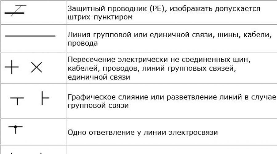
Picture of buses and wires
In any circuit there are connections and for the most part they are made by wires. Some connections are buses - more powerful conductor elements from which taps can extend. Wires are indicated by a thin line, and branches/connections are indicated by dots. If there are no points, it is not a connection, but an intersection (without an electrical connection).

There are separate images for buses, but they are used if they need to be graphically separated from communication lines, wires and cables.

On wiring diagrams it is often necessary to indicate not only how the cable or wire runs, but also its characteristics or installation method. All this is also displayed graphically. This is also necessary information for reading drawings.
How switches, switches, sockets are depicted
For some types of this equipment approved standards no images. Thus, dimmers (light regulators) and push-button switches remained without designation.
But all other types of switches have their own symbols in electrical diagrams. They are open and hidden installation, accordingly, there are also two groups of icons. The difference is the position of the line on the key image. To understand in the diagram what type of switch it is we're talking about, this must be remembered.
There are separate designations for two-key and three-key switches. In the documentation they are called “twin” and “twin”, respectively. There are differences for cases with different degrees of protection. In rooms with normal operating conditions, switches with IP20, maybe up to IP23, are installed. In wet rooms (bathroom, swimming pool) or outdoors, the degree of protection should be at least IP44. Their images differ in that the circles are filled in. So it's easy to distinguish them.

There are separate images for the switches. These are switches that allow you to control turning the light on/off from two points (there are also three points, but without standard images).
The same trend is observed in the designations of sockets and socket groups: there are single, double sockets, and there are groups of several pieces. Products for rooms with normal operating conditions (IP from 20 to 23) have an unpainted middle; for wet rooms with a housing of increased protection (IP44 and higher), the middle is tinted dark.

Symbols in electrical diagrams: sockets different types installation (open, hidden)
Having understood the logic of the designation and remembering some initial data (what is the difference between the symbolic image of an open and hidden installation socket, for example), after a while you will be able to confidently navigate the drawings and diagrams.
Lamps on diagrams
This section describes the symbols in the electrical circuits of various lamps and fixtures. Here the situation with the designations of the new element base is better: there are even signs for LED lamps and lamps, compact fluorescent lamps(housekeeper). It’s also good that the images of lamps of different types differ significantly - it’s difficult to confuse them. For example, lamps with incandescent lamps are depicted in the form of a circle, with long linear fluorescent lamps - a long narrow rectangle. The difference in the image of a linear fluorescent lamp and an LED one is not very big - only dashes at the ends - but even here you can remember.

The standard even has symbols in electrical diagrams for ceiling and pendant lamp(cartridge). They also have a rather unusual shape - circles of small diameter with dashes. In general, this section is easier to navigate than others.
Elements of electrical circuit diagrams
Schematic diagrams of devices contain a different element base. Communication lines, terminals, connectors, light bulbs are also depicted, but in addition there is a large number of radioelements: resistors, capacitors, fuses, diodes, thyristors, LEDs. Most of the symbols in the electrical circuits of this element base are shown in the figures below.


Rarer ones will have to be looked for separately. But most circuits contain these elements.
Letter symbols in electrical diagrams
Except graphic images elements on the diagrams are signed. It also helps to read the diagrams. Next to the letter designation of an element there is often its serial number. This is done so that later it is easy to find the type and parameters in the specification.

The table above shows international designations. There is also a domestic standard - GOST 7624-55. Excerpts from there with the table below.

An electrical diagram is a type of technical drawing that identifies various electrical components in the form of symbols. Each element is assigned its own designation.
All conventional (symbolic-graphic) symbols on electrical diagrams consist of simple geometric shapes and lines. These are circles, squares, rectangles, triangles, simple lines, dotted lines, etc. The designation of each electrical element consists of a graphic part and an alphanumeric part.
Thanks to the huge number of different electrical elements, it becomes possible to create very detailed electrical circuits that are understandable to almost every specialist in the electrical field.
Each element on the electrical circuit must be made in accordance with GOST. Those. In addition to the correct display of the graphic image on the electrical diagram, all standard sizes each element, line thickness, etc.
There are several main types of electrical circuits. This is a single-line, schematic, installation diagram (connection diagram). There are also schemes general view– structural, functional. Each type has its own purpose. Same element on different schemes may be designated the same or differently.
The main purpose of a single-line diagram is a graphical display of the electrical power system (power supply of a facility, electrical distribution in an apartment, etc.). Simply put, a single-line diagram depicts the power part of an electrical installation. As the name suggests, a single-line diagram is made in the form of a single line. Those. Electrical power (both single-phase and three-phase) supplied to each consumer is indicated by a single line.
To indicate the number of phases, special ticks are used on the graphic line. One notch means that the power supply is single-phase, three notches indicate that the power supply is three-phase.
In addition to the single line, designations of protective and switching devices are used. The first devices include high-voltage circuit breakers (oil, air, SF6, vacuum), circuit breakers, residual current devices, differential circuit breakers, fuses, load switches. The latter include disconnectors, contactors, and magnetic starters.

High-voltage switches on single-line diagrams are depicted as small squares. As for circuit breakers, RCDs, differential circuit breakers, contactors, starters and other protective and switching equipment, they are depicted in the form of a contact and some explanatory graphic additions, depending on the device.
The wiring diagram (connection, connection, location diagram) is used for direct production electrical work. Those. These are working drawings, using which the installation and connection of electrical equipment is carried out. Also, according to the wiring diagrams, individual electrical devices (electrical cabinets, electrical panels, control panels, etc.).

The wiring diagrams show all wire connections both between individual devices (circuit breakers, starters, etc.) and between different types electrical equipment (electrical cabinets, panels, etc.). For correct connection wire connections on wiring diagram electrical terminal blocks, conclusions are shown electrical apparatus, brand and section electrical cables, numbering and letter designation of individual wires.
Electrical circuit diagram - most complete diagram with all electrical elements, connections, letter designations, technical characteristics of devices and equipment. Other electrical diagrams (installation diagrams, single-line diagrams, equipment layout diagrams, etc.) are carried out according to the schematic diagram. The circuit diagram shows both the control circuits and the power section.

Control circuits (operational circuits) are buttons, fuses, coils of starters or contactors, contacts of intermediate and other relays, contacts of starters and contactors, phase (voltage) control relays, as well as connections between these and other elements.
The power part depicts circuit breakers, power contacts of starters and contactors, electric motors, etc.
In addition to the graphic image itself, each element of the diagram is provided with an alphanumeric designation. For example, a circuit breaker in a power circuit is designated QF. If there are several machines, each one is assigned its own number: QF1, QF2, QF3 etc. The coil (winding) of the starter and contactor is designated KM. If there are several of them, the numbering is similar to the numbering of machines: KM1, KM2, KM3 etc.

In each circuit diagram, if there is any relay, then at least one blocking contact of this relay is necessarily used. If the circuit contains an intermediate relay KL1, two contacts of which are used in operational circuits, then each contact receives its own number. The number always starts with the number of the relay itself, and then comes the serial number of the contact. In this case, we get KL1.1 and KL1.2. The designations for block contacts of other relays, starters, contactors, automatic machines, etc. are carried out in the same way.
In electrical circuit diagrams, in addition to electrical elements, very often they are also used. electronic symbols. These are resistors, capacitors, diodes, LEDs, transistors, thyristors and other elements. Each electronic element on the diagram also has its own letter and number designation. For example, a resistor is R (R1, R2, R3...). Capacitor – C (C1, C2, C3...) and so on for each element.
In addition to graphic and alphanumeric designation Some electrical components are indicated specifications. For example, for a circuit breaker it is rated current in amperes, the cut-off current is also in amperes. For an electric motor, the power is indicated in kilowatts.
To correctly and correctly draw up electrical circuits of any type, you need to know the designations of the elements used, state standards, rules for document preparation.
To understand what exactly is shown on a diagram or drawing, you need to know the decoding of the icons that are on it. This recognition is also called blueprint reading. And to make this task easier, almost all elements have their own symbols. Almost, because the standards have not been updated for a long time and some elements are drawn by everyone as best they can. But, for the most part, symbols in electrical diagrams are in regulatory documents.
Symbols in electrical diagrams: lamps, transformers, measuring instruments, basic element base
Normative base
There are about a dozen varieties of electrical circuits, the number various elements, which can be found there, number in the tens if not hundreds. To facilitate the recognition of these elements, uniform symbols have been introduced in electrical circuits. All rules are prescribed in GOSTs. There are many of these standards, but the main information is in the following standards:

Studying GOSTs is useful, but it requires time, which not everyone has enough of. Therefore, in the article we will present symbols in electrical circuits - the basic element base for creating drawings and wiring diagrams, circuit diagrams devices.
Some experts, after carefully looking at the diagram, can say what it is and how it works. Some can even immediately issue possible problems that may arise during operation. It’s simple - they know the circuit design and element base well, and are also well versed in the symbols of circuit elements. This skill takes years to develop, but for dummies, it’s important to remember the most common ones first.

Electrical panels, cabinets, boxes
On the electrical supply diagrams of a house or apartment there will definitely be a symbol or cabinet. In apartments, the terminal device is mainly installed there, since the wiring does not go further. In houses, they can design the installation of an electrical branch cabinet - if there is a route from it to illuminate other buildings located at some distance from the house - a bathhouse, guest house. These other symbols are in the next picture.

If we talk about images of the “filling” of electrical panels, it is also standardized. There are symbols for RCDs, circuit breakers, buttons, current and voltage transformers and some other elements. They are shown in the following table (the table has two pages, scroll by clicking on the word “Next”)
| Number | Name | Image on the diagram |
|---|---|---|
| 1 | Circuit breaker (automatic) |  |
| 2 | Switch (load switch) |  |
| 3 | Thermal relay (overheat protection) |  |
| 4 | RCD (residual current device) |  |
| 5 | Differential automatic (difavtomat) |  |
| 6 | Fuse | |
| 7 | Switch (switch) with fuse |  |
| 8 | Circuit breaker with built-in thermal relay (for motor protection) |  |
| 9 | Current transformer |  |
| 10 | Voltage transformer |  |
| 11 | Electricity meter |  |
| 12 | A frequency converter |  |
| 13 | Button with automatic opening of contacts after pressing |  |
| 14 | Button with contact opening when pressed again |  |
| 15 | A button with a special switch to turn off (stop, for example) |  |
Element base for electrical wiring diagrams
When drawing up or reading a diagram, the designations of wires, terminals, grounding, zero, etc. are also useful. This is what a novice electrician simply needs, or in order to understand what is shown in the drawing and in what sequence its elements are connected.
| Number | Name | Designation of electrical elements on diagrams |
|---|---|---|
| 1 | Phase conductor |  |
| 2 | Neutral (zero working) N |  |
| 3 | Protective conductor (ground) PE |  |
| 4 | Combined protective and neutral conductors PEN |  |
| 5 | Electrical communication line, buses | |
| 6 | Bus (if it needs to be allocated) |  |
| 7 | Busbar taps (made by soldering) |  |
An example of the use of the above graphic images is in the following diagram. Thanks to the letter designations, everything is clear even without graphics, but duplication of information in diagrams has never been superfluous.

Picture of sockets
The wiring diagram should indicate the installation locations of sockets and switches. There are many types of sockets - 220 V, 380 V, hidden and open type installations, with different numbers of “seats”, waterproof, etc. To give a designation for each is too long and unnecessary. It is important to remember how the main groups are depicted, and the number of contact groups is determined by the strokes.

Designation of sockets in the drawings
Sockets for a single-phase 220 V network are indicated on the diagrams in the form of a semicircle with one or more segments sticking up. The number of segments is the number of sockets on one body (illustration in the photo below). If only one plug can be plugged into the socket, one segment is drawn upward, if two, two, etc.

If you look at the images closely, notice that the symbolic image that is on the right does not have a horizontal line that separates the two parts of the icon. This line indicates that the socket hidden installation, that is, you need to make a hole in the wall under it, install a socket box, etc. The option on the right is for open mounting. A non-conductive substrate is attached to the wall, and the socket itself is on it.
Also note that Bottom part the left schematic image is crossed out by a vertical line. This indicates the presence of a protective contact to which grounding is connected. Installation of sockets with grounding is mandatory when turning on a complex household appliances such as a washing machine, oven, etc.

You won’t confuse the symbol for a three-phase socket (380 V) with anything else. The number of segments sticking up is equal to the number of conductors that this device connected - three phases, zero and ground. Total five.
It happens that the lower part of the image is painted black (dark). This means that the outlet is waterproof. These are placed outdoors, in rooms with high humidity(baths, swimming pools, etc.).
Switch Display
The schematic designation of the switches looks like small size a circle with one or more L- or T-shaped branches. Bends in the form of the letter “G” indicate an open-mounted circuit breaker, while those in the form of the letter “T” indicate a hidden installation. The number of taps displays the number of keys on this device.

In addition to the usual ones, they can stand - to be able to turn on/off one light source from several points. Two letters “G” are added to the same small circle on opposite sides. This is how a single-key pass-through switch is designated.

Unlike conventional switches, in these, when using two-key models, another bar is added, parallel to the top one.
Lamps and fixtures
Lamps have their own designations. And the lamps are different daylight(fluorescent) and incandescent lamps. The diagrams even show the shape and dimensions of the lamps. In this case, you just need to remember what each type of lamp looks like on the diagram.

Radioelements
When reading circuit diagrams of devices, you need to know the symbols of diodes, resistors, and other similar elements.

Knowledge of conditionals graphic elements will help you read almost any diagram - any device or electrical wiring. The values of the required parts are sometimes indicated next to the image, but in large multi-element circuits they are written in a separate table. It contains letter designations of circuit elements and denominations.
Letter designations
In addition to the fact that the elements on the diagrams have conventional graphic names, they have letter designations, which are also standardized (GOST 7624-55).
| Electrical circuit element name | Letter designation | |
|---|---|---|
| 1 | Switch, controller, switch | IN |
| 2 | Electric generator | G |
| 3 | Diode | D |
| 4 | Rectifier | VP |
| 5 | Sound alarm (bell, siren) | Sv |
| 6 | Button | Kn |
| 7 | Incandescent lamp | L |
| 8 | Electrical engine | M |
| 9 | Fuse | Etc |
| 10 | Contactor, magnetic starter | TO |
| 11 | Relay | R |
| 12 | Transformer (autotransformer) | Tr |
| 13 | Plug connector | Sh |
| 14 | Electromagnet | Em |
| 15 | Resistor | R |
| 16 | Capacitor | WITH |
| 17 | Inductor | L |
| 18 | Control button | Ku |
| 19 | Terminal switch | Kv |
| 20 | Throttle | dr |
| 21 | Telephone | T |
| 22 | Microphone | Mk |
| 23 | Speaker | Gr |
| 24 | Battery (voltaic cell) | B |
| 25 | Main engine | Dg |
| 26 | Cooling pump motor | Before |
Please note that in most cases Russian letters are used, but the resistor, capacitor and inductor are designated by Latin letters.
There is one subtlety in the designation of the relay. They come in different types and are marked accordingly:
- current relay - RT;
- power - RM;
- voltage - RN;
- time - RV;
- resistance - RS;
- index - RU;
- intermediate - RP;
- gas - RG;
- with time delay - RTV.
Basically, these are only the most conventional symbols in electrical circuits. But you can now understand most of the drawings and plans. If you need to know images of rarer elements, study GOST standards.