Find out the voltage on usb. How many volts does the computer's USB output produce? What is the voltage at the usb output. What voltage is supplied through the USB connector?
Read also
How many volts does the computer's USB output produce? What is the voltage on the usb output
What voltage is supplied through the USB connector?
5 (five) volts. Moreover, the current is limited to 500mA. Nothing can be changed. This voltage is standard and is used in computers and for other purposes. It is rigidly stabilized by circuits (internal) in the power supply. Outputs from several connectors at once can be parallelized. This is done to increase the maximum permissible current, for example, for connecting external hard drives 2,5.
The standard is five volts, and the current supplied by the bus is 500 mA.
IN modern models laptops output current up to 1000 mA per port and higher. Those USB ports that output 5 W are called Powered USB.
Very interesting information about important parameters here.
A voltage of 5 volts is output to any of the USB connectors on any computer.
Only the USB connectors themselves have differences in connection (shape) and, accordingly, the voltage is located on different pins of the connectors. Here is the pinout of some types:
The voltage supplied through the USB connector is about five volts. Using this connector you can charge your mobile phone, but it cannot be used for all kinds of testing of various equipment.
In theory, when a device connected via USB to a computer is recognized, exactly the voltage needed will be supplied to charge it. The connected device itself informs the relevant services and computer nodes of the necessary parameters for power supply, charging, data transfer, and so on.
The idea is 5 volts, but there are 3 and 4 volts or more
The voltage at the USB connector is 5 volts. Often 5 volts from the so-called duty channel. I understand that you need a pinout for the connector. Here she is:
Based on the diagram, you need pins 1 and 4. You will remove power from them. By the way, I still wouldn’t recommend heating the mug. The USB output is not that powerful. You can also burn it.
And further. Since you're asking, I suspect you've never encountered this. My advice to you, don’t go there out of sin... :)
The standard voltage supplied from the power supply in a computer is 5 volts. Therefore, this voltage always flows through the USB connector.
Sometimes, in order to increase the maximum permissible current, the outputs from several connectors are paralleled. For example, they do this to connect external hard disk 2.5.
You can also connect a voltage converter to the USB output, which will allow you to obtain higher values that are necessary to use more powerful devices.
A regular USB connector has 4 contacts, the voltage goes through the outermost ones. Some users even manage to connect an air ionizer to their computer in this way.
Often a thin wide connector is visually represented under the USB connector. Uninformed people believe that this name has the same connector and, when buying, they wonder why it doesn’t fit. In fact, the name is the same, but the connectors differ in size, individual parts, and data transfer speed capabilities. The voltage for the USB connector is approximately 5 Volts.
+5V power is supplied from the computer USB connector.
Of course they can be used for LED lamp or to charge the phone, but nothing more, for example, if you connect a car kettle, the system board may also burn out.
info-4all.ru
How many volts does the computer's USB output produce?
Voltage 5 Volts for all USB versions
By default, devices are guaranteed a current of up to 100 mA, and after coordination with the host controller up to 500 mA, for USB 3.0 900 mA
As the manufacturer says, this number is 5. It is worth noting that the current strength is different. It depends on the type of USB. If 2.0, then the current strength will be 0.1 A. If the other type is 3.0, then there is a different number.
USB 2.0 USB 3.0 - these are the two types of these connectors used today. First of all, these connectors have become popular due to their mechanical strength. The supply voltage for all processors in today's equipment is 5 volts. This is the voltage selected for these connectors. Previous standards of the second generation USB 2.0 provided a current value of up to 0.5 amperes. The later version of USB 3.0 allows load removal of up to one amp. Through this connector you can not only carry out digital communication with various devices, but also charge various household equipment powered by batteries.
You are confusing 500 mA and not 0.1 ampere. This is 0.5 ampere
Most USB outputs on a computer produce a voltage of about 5 volts, and as for the current, we can say that it is equal to 500 mA or 0.1 Ampere (for USB 2.0) is no longer provided, otherwise the device may simply burn out.
The current strength in USB in a computer is about 500 mAmps.
The voltage is only 5 volts.
But this is for USB 2.0, for USB 3.0 the current is different, it is 900 mA.
This is done in order to transfer information to sources such as a flash drive, phone, etc.
So that the devices do not burn out.
Approximately 5 volts and a current of about 500 mA.
The computer's USB output produces five volts.
Now about the current strength, it is different. Everything depends on USB.
For USB 2.0, the current is five hundred mA, which is 0.1 Ampere.
For USB 3.0, the current is already nine hundred mA.
For USB, the standard voltage is Five Volts. But Amperes are different, it all depends on the type of USB; USB 2.0 has a current of about 100A, it can be increased to 500A, but USB 3.0 will have a current of 900A. But if you apply a voltage of 500A, the device may burn out on 2.0 USB.
It all depends on the connector of the computer or laptop. USB 2.0 connector current reaches five hundred mA. And already in USB 3.0 the current reaches nine hundred mA. Each manufacturer chooses what to install on their devices based on the technical parameters.
All USB outputs of the computer into which a flash card is inserted, a wire for transferring information to a hard disk, mobile phone, camera, player and other equipment, produces a voltage of about five volts.
Today it is difficult to imagine life without this uniquely convenient USB connector. The first versions of this port appeared in the mid-90s of the last century. This was version 1.0. It set the direction for the development of USB as a means of communication. As the output voltage was set at 5 V back then, it remained the same in the latest versions of USB - 2.0 and 3.0. It doesn’t matter what type this connector is - standard classic or mini and micro, the voltage on USB is the same. But in latest version USB 3.0 changed the current strength as the data transfer speed increased to 5GB. Now the current in the port is 900 mA, versus 500 in previous versions.
USB is a serial data transfer interface for medium- and low-speed peripheral devices. I searched the Internet and found that the USB output of the computer produces a voltage of 5 volts, here is a picture with additional information.
info-4all.ru
How to avoid damaging your USB port -
Often laptop manufacturers, and then the sellers who sell these products, give a decent warranty on the hardware they offer, with just one caveat: the warranty does not apply to USB ports. Why? Presumably, because this is the most vulnerable place of the computer, and inexperienced users, who are the majority, as a result improper use USB interface can easily damage it. Of course, developers are struggling with this problem and using different protective measures in different laptop models. But until the problem is finally resolved and in order to avoid trouble, users are advised to adhere to certain rules. The same applies to desktop computers.
All failures of using a USB port can be divided into software and hardware, that is, physical. Software failures are easier to fix. At least they will not require material costs, although they may take quite some time. In this case, you may need to update or select a driver, BIOS setup, and in difficult cases - reinstallation operating system. Physical malfunctions will require disassembling the computer, searching for and replacing burnt out parts, and the most unpleasant thing is replacing an expensive controller chip, which only a specialist can handle service center.
USB Energy Parameters
The most common option today is USB 2.0 connectors built into computer equipment. Less common USB versions 1.1, which began the widespread introduction of this type of interface at the end of the last century. The more advanced USB 2.0 began to be used in 2000; starting in 2008, USB 3.0 was released. Let's consider only the energy parameters of common ports.
USB port version 2.0, like more new version 3.0, has special contacts to which a voltage of 5 V is output. This voltage is usually used to power external devices connected to the computer, controlled through the port, and also as a power source direct current. Such a source can power a USB flashlight, a small audio system, or serve to charge a mobile phone battery.
However, the port's energy capabilities are not unlimited. The standard current it can provide is as follows. For a USB 2.0 port, the output current cannot exceed 500 mA, for a USB 3.0 version - 900 mA. When a slight overload occurs, it leads to a voltage sag, which can cause the connected device to malfunction. If the overload increases, the voltage decreases even more. In this case, there is no need to talk about the operation of the device, and the port itself may fail as a result of severe overheating of the circuit elements. Moreover, irreparable harm can be caused short circuit power buses, which will cause burnout protective elements port.
What and how to connect to the USB 2.0 connector
Each computer can have from 2 to 6 USB ports installed, and even more on special order. Anything connected to each should not draw more than 500 mA of current. This guarantees normal operation devices and maintaining the functionality of the port itself. Low-power and serviceable loads, such as flash drives, a mouse, a keyboard or a web camera, cannot harm the interface. Powerful loads should be treated with care.
An example of a powerful load would be an external hard drive and other devices with a current consumption of 500 milliamps or more. Often such devices are equipped with two connectors connected in parallel in order to use two different USB 2.0 ports to connect them. Load capacity this method supply will increase to 1000 mA. Sometimes the external device has its own power supply, then Electric Energy the port is not consumed at all, and it will function in lightweight mode.
Everything that was said here regarding the USB 2.0 port is also true for its 3.0 version, with the only difference being that instead of a maximum load current of 500 mA, it has a limit of 900 mA.
Errors when connecting powerful loads
One of the mistakes is as follows. Let's say the connected device (external hard drive) has two paired USB connectors. One of them is the main one, having a power line and a data line, the other is an additional one, equipped only with conductors for power supply. Often the consumer, due to inexperience or forgetfulness, can use only one main connector, leaving the additional connector unconnected. If the device draws 800 mA current, it will overload the USB 2.0 port, causing it to fail.
A similar situation can arise when the user uses a passive USB interface splitter - a device that increases the number of USB sockets. Such a device is designed to connect an appropriate number of low-power loads and cannot in any way increase the maximum current of the source port. If the consumer did not understand this and caused an overload through powerful loads, then troubles should be expected.
Consequences of port failure due to overload
To prevent an overload or short circuit of the power supply bus of the USB port from leading to more serious damage to the computer, the developers build in special means protection. For example, a fuse, a current limiting resistor, a self-resetting fuse. In each case, the consequences may be different.
If the fuse blows, the power supply to the port is turned off and it becomes inoperable. When a limiting resistor (usually an SMD chip) is overloaded, it becomes very hot, part of its resistive layer burns out, causing the resistance to increase, and therefore the load current decreases even more. Such a “fried” port will only be able to function with low-power loads.
. Author - Kargal.general information
USB connectors for connecting gadgets
IN last years There has been a noticeable trend towards unifying the data/power connectors of different gadgets different manufacturers(perhaps only Apple continues to go its own way).
In order to minimize the size, mini-USB or micro-USB connectors are used, each having five contacts and the same pinout.
The pinout of connectors and cable connection options are shown in the table ▼
| Pin# | 1 VBUS |
2 D− |
3 D+ |
4 ID |
5 GND |
| Color wires |
------ | ------ | ------ | ------
None |
------ |
| Red | White | Green | Black | ||
| Data cable | +5V input | -Data | +Data | NC | GND |
| OTG —cable | +5V output | -Data | +Data | connected→ GND | |
| Memory "DVR" | NC | NC | NC | +5V input | GND |
| "Garmin" | +5V input | -Data | +Data | 18 kΩ→ GND | |
| Memory "Motorola" | +5V input | NC | NC | 200 kΩ→ GND | |
| Charger "Glofish" | +5V input | NC | NC | connected→ GND | |
Two cables correspond to the main USB standard:
- "Data cable"- used for charging and information connection to a PC in “Slave” mode; in this cable pin4 is not connected to anything (NC - not connected).
#) In all charging (non-OTG) cases of the data bus ( D− And D+) are used in two ways - within ~2 seconds after the appearance of the external supply voltage on pin1, the gadget determines the potentials and properties of the data lines. The gadget needs to “know” the type of charging port to determine the maximum permissible current for a given charger (hereinafter referred to as the charger). After identifying the port, the gadget allows itself to consume current for operation/charging, and if the port turns out to be a signal port (types SDP or CDP), then also exchange data as a USB peripheral (Slave) device.
- "OTG cable"- the connection between pin4 (the “Ident” input) and pin5 (GND) is usually made directly in the cable part of the connector and forces the gadget to operate in “Host” mode - to power and service the connected peripherals (mouse, flash drive, external keyboard, etc. ). This cable does not allow external power supply or charging of a gadget that has USB-OTG mode. The BCv1.2 standard allows for charging in Host mode a USB-OTG device that recognizes the port type ACA(no longer with this cable), but nothing is known about the existence of such devices in nature.
Taking advantage of the laxity of compliance with the standard, many gadget manufacturers indulge in some pranks using connector contacts without notifying users. This circumstance makes it difficult to replace the standard charger with a universal one in case of loss/breakage of the standard charger or when organizing an additional charging station. For example:
- "DVR memory"- there are many models of car DVRs, which can be powered in two ways:
1. When connected with a standard data cable, the recorder “comes to life”, but does not start recording, but offers long boring conversations (through the menu, using buttons) to explain to the recorder what is now required of it.
2. When connected with a special “DVR memory” cable (+5 V power is supplied to pin4), such a recorder immediately starts recording, which allows you to organize its automatic switching on in the car when the engine starts. - "Garmin", "Motorola charger"- pin4 is connected to pin5 (GND) through a resistor, the value of which sets the gadget’s operating/charging mode (see article “”).
- "ZU Glofish"(and the successors of Glofish) - pin4 is short-circuited to pin5 (GND) to allow consumption of more than 0.5 A (see topic on the 4PDA forum).
Unfortunately, there is no easily accessible information on such tricks in relation to specific models of gadgets - manufacturers are either being cunning to protect their business, or are embarrassed by their perversions. There are only scattered and not very clear mentions on the forums. We can only hope that the user community will mobilize and create a database.
Custom characteristics of chargers (chargers)
Voltage
Chargers with USB connectors for connecting the load are rated at U out = 5 V and usually actually correspond to the USB specification - U out = 4.75 ÷ 5.25 V. (Although there are ).
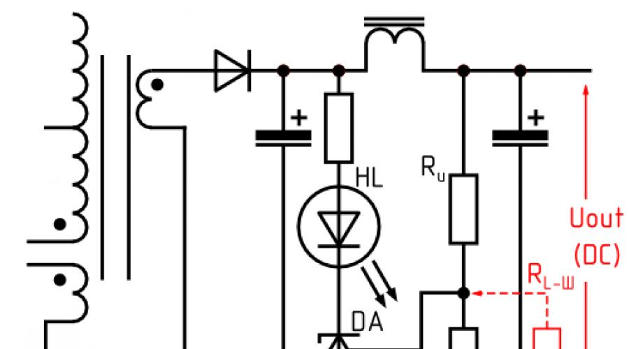
Typical scheme low-voltage part of a high-quality network charger ▼

Here HL is the optocoupler LED feedback, DA is a parallel stabilizer, actually used in comparator mode. The complete scheme seeks to establish such output voltage U out so that the voltage at the output of the divider R U / R L is equal to the internal reference voltage U ref of the DA stabilizer. For stabilizers of the TL431 family U ref = 2.5 V, for the TL family V 431 – U ref =1.25 V. The value of U ref can actually be measured with a digital voltmeter at turned on
#) Carefully! Primary side under high voltage.
To increase U out by ~10%, it is necessary to change the parameters of the R U / R L divider so that the voltage at its output (the connection point between R U and R L) is equal to U ref not at 5.0 V at the output of the charger, but at ~5.5 V. The easiest way to do this is by adding a shunt resistor R L -Ш. Its value should be:
For U ref =2.5 V: R L-Ш =5*R L ;
For U ref =1.25 V: R L-Ш =7.5*R L ;
(The value of R L in a specific memory can be determined by its marking or actually measured with a digital ohmmeter on turned off memory and disabled load).
#) For poking around in the internals of the charger, it would be nice to have a collapsible (not glued) case.
Automotive memory (ASU)
In automotive chargers, step-down (Buck, StepDown) PWM converters are usually used. Typical output part of the circuit ▼

Here:
S.W.- output of the built-in power switch of the converter;
C BS- voltage booster capacity, used only for converters with N-MOS (or NPN) power switch;
VD1
- clamping (fixing) diode, used only for simple (non-synchronous) converters;
C COR– feedback correction capacitance (may not be used);
R U And R L- the initial feedback divider, which sets the output voltage;
R L-SH- correction resistor added for increase output voltage.
The complete circuit seeks to set the output voltage U out such that the voltage at the output of the divider R U / R L is equal to the internal reference voltage U FB of the stabilizer.
The value of U FB can be taken from the data-sheet of the converter used or actually measured with a digital voltmeter on turned on and a loaded memory, through a 50÷100 kΩ resistor (to ensure the stability of the circuit during measurement).
To increase U out by ~10%, it is necessary to change the parameters of the divider R U /R L so that the voltage at its output (the connection point between R U and R L) is equal to U FB not at 5.0 V at the output of the charger, but at ~5.5 V. The easiest way to do this is by adding a shunt resistor R L -Ш. Its value should be:
For U FB =1.23 V: R L -Ш =7.5*R L - for converters MC34063, LM2576, LM2596, ACT4070;
For U FB =0.925 V: R L -Ш =8.2*R L - for converters CX8505, RT8272, AP6503, MP2307;
For U FB =0.80 V: R L -Ш =8.4*R L - for converters AX4102, XL4005.
(The value of R L can be determined by its marking or actually measured with a digital ohmmeter on turned off memory and disabled load).
To reduce U out, the easiest way is to shunt R U.
Electronics gadgets
Charge controllers
OZ8555/o2micro
(Used in tablets based on RK3066 – Hyundai Hold X700, Window N101/YUANDAO N101; PIPO M1, PIPO Max-M8 pro, PIPO Smart-S2; CUBE U9GT3)
Contains a DC/DC converter for charging the battery and powering the gadget. Requires tension external power supply 5.5÷5.9 V (at least 5.4 V at the input to the gadget) and is used in gadgets with a separate (non-USB) charging connector.
I didn’t find a data-sheet on the OZ8555, but it seems that its threshold for protection against insufficient supply voltage UVLO (Under Voltage Lock Out) is 5.1÷5.3 V instead of the usual 3.9÷4.5 V for 5-volt gadgets. This property would completely explain Incorrect operation from a “foreign” charger delivering less than 5.4 V.
Discussion: 33 comments
I have not encountered or experimented with this matter in practice.
Answer
Hello.
I have a 0.6mm diameter cable, two wires, about 6-8 meters long, laid in my wall from the shield. I decided to hang the tablet on the wall and use this cable for charging. But judging by the ampere application, when the screen is on, the charge current jumps from 600 to 200mA, the average is 250-300. However, the tablet does not charge, even with the screen turned off. I tried all the charges, the result is the same. By the way, at the end of the cable at the USB connector on the tablet side, I made a date + and - jumper, before this the tablet did not detect charging at all. Next, I measured the resistance by closing the circuit from one side of the tablet - it turned out to be about 3.5-4 ohms, this is both wires back and forth if you close and measure on the other side. Quite a lot, apparently because of this the voltage drops. I measured the voltage under load in the shield (there is a twist there) - 4.7V, while without load at the end of the tablet it was 5.15V. I can’t measure it under load on the tablet.
And now, actually, the question is - if I understand physics correctly, then to increase the current I need to increase the voltage on the power supply, volts to 6-6.5, so that minus losses it reaches 5.2, -5.4 V, do you think such a trick will work?
Good day. Thank you very much for the site.
Have you found any information on the operating principle/identification of QuickCharge 2.0-3.0?
And what if a device that supports such charging is stupidly given 9 or 12 volts per USB port? What do you think the reaction will be?
I tried to submit to Sony phone Xperia X from 4.9 to 6 volts. The current consumption in amperes does not change. I'm afraid to apply more than 6 volts.)
Answer
After reading many sources, I found the same information everywhere: the USB 2.0 port is capable of delivering no more than 500mA, providing power of no more than 2.5W. However, some things cast doubt on this.
First of all, about useful things. If you select the “USB Root Hub” properties in the device manager (I don’t remember how it is in Russian, look at all devices), then the second tab “Power” will display information about the connected device: how many milliamps it requires. The value is taken from the filling of the connected device, this is not the actual current consumption:
- some flash drives require 500mA (Kingston, Transcend), and some require 200mA (Toshiba). Moreover, it has been experimentally proven that a Toshiba flash drive works on any 1.8 meter USB extension cable, even those not made to the standard. It turns out that the less a device consumes, the more chances it has to make money on a USB extension cable or low-quality front connectors of the case;
- and indeed: optical mouse, consuming 100mA, works without problems on a 3-meter USB extension cable (and all the flash drives there are already “bye-bye”);
- the USB A-B cable going to the printer reflected the recommended value of 98mA;
- USB-HDD "Silicon Power" 320GB showed a value of 2mA (connected to one USB port and operates successfully). The reason was found out: only 1 byte is allocated for the value of milliamps in the OS, and the maximum value of this counter is 255. Each counter value is equal to 2mA. This means USB-HDD has gone beyond the limits of what is possible maximum number, and the counter resets to +1 (corresponding to the number 514mA or 1026mA). But this is more than the 500mA stated in the standard!
This was the first doubt about the truth of I max = 500mA for the USB port.
Second: one hub serves several USB ports at once, and it is written that the maximum is 500mA per port. This means, in my case, the hub is capable of delivering 2.5A (since it is responsible for 5 ports). If it is capable of delivering a total of 2.5A, what should stop it from issuing, for example, 2.5A to one port, and simply blocking 4 others.
Third: the power supply data of the disassembled USB-HDD is 5V/0.85A. This is already more than 0.5mA. Moreover, it was experimentally found that starting the HDD (reactive load) requires much more current than indicated on the HDD.
Fourth: I powered the router via a USB cable, and even then I somehow knew about the value of 1200mA. Here it is, the struggle of paradigms: heard there, seen here, said there, written here...
All the prerequisites for the experiment are there to obtain real numbers of current strength of this HDD. Over the course of a month, I will crash into the USB A-miniB cable with a high-precision ammeter for 20,000 rubles - and take readings from it. With your eyes or telemetry - whatever happens.
(added 04/07/2015): The experiment with the USB connector was successful, and my guesses were confirmed. The following equipment was used:
- multimeter DT838 (here’s a “high-precision” one for you...);
- active load: external HDD Samsung Momentus ST320LM001, USB coffee heater Orient W1002B;
- passive load: 4 resistors C5-16V-8W 1Ohm ±1%;
- USB plug;
- EliteGroup G31T-M7 and Gigabyte C51-MCP51 motherboards.
In the process of connecting the active load separately and in parallel, it became known:
- the maximum current for the HDD (0.85A) is extremely accurate, it was obtained when spinning up the disk and when initializing it after Windows boot(fractions of a second). Current in idle mode: 0.28-0.35A, in transfer mode at a speed of 28MB/s: 0.56-0.63A;
- the heater consumes a constant 0.6A, including during start-up: there is no reactive load. A coffee warmer with a power of only 3W cannot be considered a serious household item;
- at parallel connection load we managed to get a value of 1.19A. This value exceeds that stated in the USB 2.0 standard by 2.38 times.
Then the question arose: what is the correct limit? An inexperienced technician caused a short circuit when I entrusted him with the issue of soldering, but the equipment was not damaged, and the short circuit was not in vain: the ammeter recorded a constant passage of 3.3A through it, which means motherboard there is some kind of ampere limiter (for example, in the controller). Moreover, the restriction also worked when the PC was turned off.
To avoid damaging the active load, it was decided to abandon it in favor of a passive one, which transfers all the energy into its own heating: resistors. Oddly enough, high-power and low-resistance resistors were in short supply, and only 4 were found. Moreover, they are 25-30 years old, and their shelf life of this type is 15 years. What a surprise it was when, after finishing the experiments, it turned out that the resistance of one of them increased by +50%, to 1.5 Ohm. Then all the “errors” in the experiment became clear.
First, 1.45A was obtained, which successfully heated the resistors for several minutes. Further, lowering the resistance, a current value of 3.05A was achieved. And it was at this value that the automation (motherboard or Windows?) disconnected the USB connector, but in some unusual way: by reducing the current value not to 0, but to 0.4A.
So, the current limit for the USB connector hangs in the range )