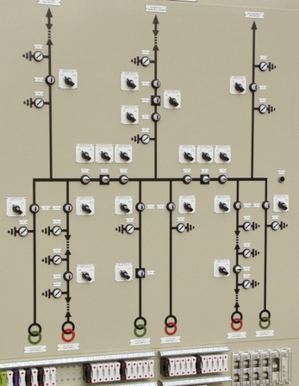
Tactile mnemonic diagram for indoors. Telemechanics in the power supply of industrial enterprises - mnemonic diagrams and electrical equipment of dispatch boards and consoles Dispatcher boards
Read also
Software for maintaining a mnemonic diagram and electronic log of an energy facility
The dispatch information system is an integral part of the Modus software package. It is based on the application maintaining a mnemonic diagram and electronic journal dispatcher
Software for maintaining a mnemonic diagram and electronic journal, together with a set of extensions described in sections Integration with databases, Working with telemechanics data and other extensions, amounts to Dispatch information system.
The operation of the program is based on the operator maintaining an operational diagram of the power facility, presented in graphical form (mnemonic diagram). The operator makes changes to the circuit in accordance with changes in the state of the power facility. It is possible to connect a system for collecting telemetric information, as well as a telecontrol system, in this case the program acquires the capabilities described in the section Working with telemechanics data.
The electronic log is filled out automatically in accordance with changes in the operational scheme.
The software is focused on maintaining diagrams of any level - PES, RES, urban electrical networks, power supply diagrams industrial enterprises, power systems, substations, electrical circuits of stations, relay protection and automation equipment, SDTU devices.
The software is especially useful in those enterprises where there are large power supply circuits with a relatively small amount of telemechanics. First of all, these are city networks, distribution networks, and industrial enterprises.
This application was previously called Electronic Journal, and before that Operational Journal. Currently, these names are not used, since they do not accurately convey the main purpose of the program.

Mnemonic diagram management software
Main features:
- Allows you to keep track of switching on both the primary (switching devices) and secondary (state of relay protection and automation) circuits;
- Provides verification of the admissibility of performing operations based on switching rules in electrical installations;
- Allows you to carry out switching according to forms or switching programs, or operationally;
- Allows you to keep track of the location of fire safety equipment, repair crews, and areas where repair work, accident sites, installed portable protective grounding;
- Allows you to display energy facilities on diagrams
- Has developed means of printing circuit states (normal, operational, on-demand this moment time), provides search and selection of circuit elements on the diagram according to a number of criteria;
- Provides printing of the Electronic Journal and generation of reports based on the data contained in it.
Log service functions
- Examples of magazine samples:
- from the moment the operator registers in the system;
- from the operator’s previous registration in the system;
- changes in the operational scheme for a specified period of time;
- associated with the difference between the operational scheme and the normal one;
- emergency switching;
- installed/removed portable groundings, switched on/off contact points. - Display of de-energized and grounded areas
- Export selections as files.
- Quick transition between journal entries, diagram elements and items in switching forms.
- Showing deviations of the state of the operational scheme from the normal scheme and from the state at the time of the last shift.
- Printing and displaying object mimic diagrams
- In a state at the specified point in time
- IN current state operational scheme
- In normal circuit condition
- Display of equipment that is faulty, de-energized, disconnected, unused, etc.
- Display of cable chains and air lines and TP included in the feeder
- Displaying in the tooltip the PS, the feeding center and the RP from which the feeder is powered
- Diagnosis of incorrectly powered feeders
- Ability to view the current state of the diagram and log by other users on the network.
Schema service functions
- Displaying the sample result directly on the diagram.
- Viewing data associated with circuit elements (for example, passport or calculation data) from databases available to the customer. A standard mechanism for connecting such databases is built into the software.
- Configuring the display of the diagram “on the fly” (without redrawing) in accordance with the standards adopted at the enterprise or the operator’s preferences.
- Automatic arrangement of line directions from the supply center to the consumer
- Automatic formation and illumination of normal (according to normal current divisions) and current (at a certain point in time) feeders.
- The complex provides a multi-page transition system from general scheme networks up geographical map terrain.

Performed organizational and technological tasks:
- Approval of the normal scheme and permission of users to work.
- Acceptance (handover) of shifts by the facility’s operational staff, transmission of shift information.
- Maintaining an operational plan, maintaining an electronic journal.
- Using a system for preparing and recording the execution of standard and one-time switching forms and switching programs.
- Maintaining a list of current tasks.

Types of journal entries
- Marking accident sites.
Actions with objects - fixing switchings, setting the removal of operational current/blocking, setting the removal of protections, etc.
Acknowledgment of telesignals and messages about exceeding setting values.
Verification actions, results of walk-throughs and inspections.
Negotiations between operational personnel, orders.
Arrangement and accounting of field and repair teams at destinations.
Installation/removal of mobile elements - portable grounding, poster, looping, etc.
Editor of operational tasks
As part of the mnemonic diagram and electronic journal management software, the “Operational Tasks Editor” program has been implemented. It is designed to monitor the status of operational tasks at the dispatcher’s workplace.
The software allows you to:
Drawing up operational tasks by performing operations on an electronic layout of a power facility.
Checking the operational task using a mnemonic diagram (layout) with control of the correct execution of operations:
switching on energized grounding blades;
disconnecting disconnectors under load;
control of operational blocking;
showing on the diagram in dotted lines the disconnected electrical sections of the circuit, etc.
Marking the completion of operations in operational tasks, which ensures control over the real state of active operational tasks.
Quick access and switching between active tasks.
Saving the active task to a file and loading from the file in an up-to-date state.
Possibility of viewing mnemonic diagrams of power facilities.
Possibility of printing an operational task in the form of a switching form of a standard form.
Drawing up regular switching forms and working with them.
Preparation and storage of a database of standard switching forms.
Checking the possibility of executing a standard switching form in the current state of the power facility circuit.
Creation of regular switching forms based on standard forms in in electronic format and work on them.
The program provides control over the status of several simultaneously executed operational tasks. The dispatcher can switch between them in the list of operational tasks window. The editor of operational tasks is integrated with the software application for maintaining a mnemonic diagram and an electronic journal.
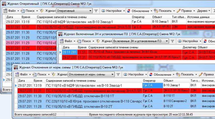
Additional journals included in DIS
Starting from version 5.20, the DIS includes a number of additional journals:
- Changes in the consumer power supply,
- Technological violations,
- Consumer requests,
- Equipment defects...
Data from additional logs are stored in the EZh database and contain information about the parameters and time of the event, the power facility, an explanatory part, and data about the person who made the entry:
The developed magazines are fully integrated with electrical diagram. An automatic transition from a journal entry to a schema element and back is provided. It is also possible to operate journals without a schema.
All journals allow you to generate reports in Word format
Power supply change log
The power source change log allows you to keep track of changes in the power supply to consumers.

Power supply change log form
Logbook of technological violations
The log of technological violations (TN) records:
- Time of occurrence of TN
- Object of occurrence of TN
- Number of de-energized transformer substations, substations, healthcare facilities, heat supply
- Power off
- Time to eliminate the VT putting the facility into operation
Report data on de-energized subscribers is generated automatically based on pre-prepared subscriber directories and analysis of the current network configuration.

Technological violation log form

Technological violation log form
Log of consumer requests for power failures.
To organize the process of registering consumer applications in the DIS, a corresponding module has been developed that allows you to record information about a complete or partial loss of power supply, using corporate information systems created at enterprises.

Consumer Application Log Form

Consumer applications log form
Log of defects and problems with equipment and the progress of their elimination
A module for recording defects and equipment problems has been developed, fully integrated with the electrical circuit. At the same time, an automatic transition from a record to a circuit element and back is ensured.
The module provides the ability to select records by:
- the planned date for eliminating the defect (indicating a specific date or indicating a period),
- the department responsible for eliminating the defect,
- all defects that have not been eliminated, defects for which the period for elimination has expired;
The module allows you to reschedule defect elimination.
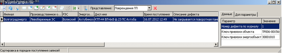
Defect log form 
Defect log entry form
Security and legal aspects
All changes are entered into the log on behalf of the dispatcher who took over the shift. Forgery and retroactive modification of records in electronic magazine excluded. To insure against software failures, it is possible to maintain a hard copy (print) simultaneously with recording entries in the journal.
Connection of telesignaling / remote control
control room information system can be considered as an integral part of the OIC (top level), in which support is implemented operational switching and there are ample opportunities integration.
IN software The ability to receive teleinformation and telemeasurements, as well as telecontrol of energy facilities through the industrial OPC software interface is built in. This software interface is supported by many modern complexes telemechanics, as well as OIC/SCADA systems.
The exchange of such complexes is carried out without additional programming. In the case of using information from systems that do not support OPC, docking can be carried out on a contractual basis by the Modus developers or another contractor (the best option is usually to develop an appropriate OPC server).
Thus, software package can be considered as an integral part of the OIC (top level), which implements support for operational switching.
Purpose . Mnemonic diagram (screen form) is a visual graphic representation of the technological process, integrated with monitoring and control tools. It is the most important source of information about the nature and structure of connections, the current state of variables (including those related to violations of technological conditions, accidents, etc.) and allows the process operator:
· facilitate memorization of the technological process and the purpose of devices and controls;
· determine methods of action under various operating modes of the object;
· help simplify the search and identification of the necessary information for promptly making the right decisions.
Graphic components . All SCADA systems include tools that allow you to create both static elements of mnemonic diagrams (contour images of technological devices, pipelines, etc.) and animate (animate) these elements (create dynamic objects). These funds include:
· sets of graphic drawing primitives (line, rectangle, ellipse, curves, text) and means of their arrangement to create unique own objects);
· ready-made libraries of standard graphic objects: technological objects (devices, mechanisms, machines, etc.), displays, pointers, sliders, buttons, switches used to display variables and control the process. These libraries can be extended by the user. When constructing a mnemonic diagram, first the drawing is carried out
static image of the working window. Usually these are devices technological process or their technological sequence, pipelines, background, explanatory text, etc.
The next step is to give the mnemonic diagram dynamics, i.e. animation of drawn (or selected from libraries) elements. Animation refers to the ability of elements to change their properties when process variables change. The properties that can be changed are the line thickness, line color, and style, the fill color and style (if it is a filled shape), and the size, position, and orientation of the elements. It is also possible to directly enter variables (in numbers and text, sliders) and control the process using buttons and switches (Start/Stop, On/Off, Call up Window, etc.).
Construction principles . With a wide variety of technological processes, designing a good mnemonic diagram is in many ways an art, but we can recommend general principles constructions:
– brevity and clarity– the mnemonic diagram should be simple (the contours and proportions of the devices are close to the appearance of real prototypes), should not contain secondary elements, and the displayed information should be clear and specific, convenient for perception and further processing. The mnemonic diagram should provide a minimum number of variables, but adequate for monitoring and control, and should not be “overloaded” with information for clarification (minor trends), which is more convenient to be nested in the form of pop-up windows called up at the operator’s request;
– maximum linearity process images, i.e. it is advisable to highlight the main line of the process, obeying the visual rule: reading “from left to right” and “top to bottom”, minimal use of parallel contours, which will greatly simplify perception
- autonomy– isolation from each other of the sections of the mnemonic diagram corresponding to autonomously controlled and controlled objects and units. These isolated areas should be clearly separated from others and have a complete, easy to remember and distinct structure.
– unification– symbols of similar objects and processes must be combined and unified whenever possible;
- visual emphasis on control and management elements– First of all, elements that are essential for assessing the condition, making decisions and influencing the controlled object should be highlighted (by size, shape or color) (i.e. they help quickly navigate, identify and eliminate deviations and malfunctions);
– taking into account the human factor– the mnemonic diagram should be developed and improved taking into account the opinion of the operating personnel.
To evaluate mnemonic diagrams, the following are used:
– information content coefficient – the ratio of the number of passive (static) elements and active (dynamic);
– field filling factor – the ratio of the number of passive elements of mnemonic circuits to the total number of elements of the mnemonic circuit.
When designing mnemonic circuits, several options are usually offered. The final one is chosen by experiment (the activity of an operator is simulated on a computer with various options mnemonic diagrams). The evaluation criteria are the time required to solve problems and the number of errors made.

In Fig. Figure 2 shows the main areas of the mnemonic diagram. With a horizontal dominant presentation of information, the following zones are distinguished: basic information area– reflects the general structure of the technological process. It contains the main apparatus, pipelines, as well as the information load accompanying the technological process.
zone additional information – buttons for trend graphs, reports, “start/stop”, etc. can be located here.
switching zone– is due to the impossibility of rationally displaying all information in one window (“the curse of the format”).
Using area tools, it is possible to call additional windows on which alarms, trends (per day, month, year), and individual sections of the process are detailed. This approach relieves the mnemonic diagram and makes it possible to obtain the necessary information about the object that deserves attention at the moment. A clear difference with the vertical dominance of zones is that area 2 (additional information) is located to the right of area 1 (basic information). This is primarily due to the size of the described objects (the displayed process is small in volume), which allows more space to be allocated for explanatory information. This arrangement of areas can be used for pop-up windows, i.e., detailed consideration of individual sections of the technological process.
For ease of visual perception functional diagrams objects, controlled or managed, use mnemonic diagrams - graphic images diagrams of these objects. A mnemonic diagram can display, for example, a CNC machine shop, some technological process or system, such as an energy network. In other words, a mnemonic diagram is an informational conditional model of a system or process in the form of symbols indicating parts of the system, as well as their connections.
The mnemonic diagram graphically reflects the structure of the entire system, thereby facilitating the work of the operator, who, thanks to such a diagram, can more easily remember the structure of the system, the relationships of parameters, the purpose of certain controls, instruments, machines, etc.
For an operator managing processes, a mnemonic diagram serves, perhaps, as one of the most important sources information about the processes currently occurring in the system, about the structure and nature of these processes, about the current status of the system, in particular, about accidents and violations of normal operating modes.
If the controlled object has a complex structure, has many parameters that must be quickly controlled, and is technologically complex circuit. If during the operation of the object itself technology system may change - in these cases, mnemonic diagrams turn out to be very, very effective tools. They can display the states of individual devices, machines, units, the values of various parameters, and also provide general information about the flow of the technological process.
An operator working in conditions of an abundance of information coming to him, thanks to mnemonic diagrams, can more effectively carry out information search, since a mnemonic diagram always implies logic; it displays real connections between the parameters of the object to be managed or controlled.
With the help of a mnemonic diagram, the operator can easily systematize logically and timely process the information received by him; technical diagnostics in case of deviation from the norm are also facilitated. The mnemonic diagram thus serves as an external support for accepting the best solution and implementation of the correct control actions.

Mnemonic diagrams are always created adhering to a number of principles that have been formed over many years practical application mnemonic circuits. And one of the main principles is brevity. The mnemonic diagram should not contain anything superfluous, it should be as simple as possible. In the absence of obscuring elements, the displayed data should be displayed clearly and specifically, as briefly as possible, so that they can be easily perceived and subsequently processed promptly.
The principle of unification (generalization) implies highlighting on the mnemonic diagram and using the most significant features objects, that is, non-essential design features systems do not need to be displayed on a mimic diagram. Symbols of similar processes and objects should be combined and unified.
The principle of emphasizing control and monitoring elements dictates the need, first of all, to highlight the shape, color and size of the most important elements, serving to monitor the condition and encourage adoption important decisions regarding the impact on the control object.
According to the principle of autonomy, it is important to separate from each other the parts of the mnemonic diagram corresponding to autonomously controlled and monitored units and objects of the system. Isolated parts are clearly delimited from others, subject to the principle of structure, according to which they must have a structure different from other structures and be easy to remember, while the structure must appropriately reflect on the mnemonic diagram the nature and basic properties of the object.
The principle of spatial correspondence of control and monitoring elements obliges the indicators and instrumentation to be located strictly in accordance with the location of the corresponding control elements, so that the law of compatibility of the reaction with the stimulus is observed.
One of key principles When creating mnemonic diagrams, the principle of using stereotypes and habitual associations is used. The symbols of parameters should be associated by the operator with standard symbols for these parameters, which are generally accepted, and instead of abstract icons it is better to use symbols denoting exactly the corresponding processes and objects.

The figure shows an example of different designations for the same parameters. Here in the top line are shown letter designations, in the second line there are their symbols, and in the third line there are mnemonic symbols. Obviously, mnemonic symbols are similar in their contours to the outlines of letters, therefore mnemonic symbols are more preferable.
Practice shows that the use of mnemonic symbols leads to a reduction in the number of errors and a reduction in the time that the operator spends on symbol recognition by 40%.
With all this, the mnemonic diagram does not have to completely copy the technical structure. Its task is to display the logic of managed and monitored processes, simplify the search and identification of required information for the operator, and help quickly accept correct solution and perform the necessary operation on time.
Mnemonic diagrams can be used for control rooms or operators. Operator rooms display a single technological complex, and control rooms display a dispersed system consisting of objects, complexes, units, etc. In this regard, there are differences between these two types of mnemonic diagrams in the degree of detail and in the detail of displaying objects.

If the operator performs switching directly on the mnemonic diagram, then such an operator mnemonic diagram is called operational. If a mnemonic diagram serves only to inform the operator, then it is a non-operational mnemonic diagram. Dispatcher mnemonic diagrams are divided into facial and light based on a similar basis.
The composition of the operational mnemonic diagram, in addition to display devices and measuring instruments, signal and visual elements, calling or individual type controls are also included. Mimic dispatcher mnemonic diagrams have switches for manually removing signals and receiving data on the mnemonic diagram about the current real state of the control object.
If on a mnemonic diagram each of the informing elements is associated with an individual sensor, such a mnemonic diagram is called single-object or individual. If it is possible to switch between several objects of the same type, then such a mnemonic diagram is called multi-object or selective (calling).
Thus, calling mnemonic diagrams can switch between several sensors of one object or between objects. Calling mnemonic diagrams allow you to reduce the area of the panel, use one instead of several, save on the installation of devices and information processing systems, and also facilitate the operator’s work by simplifying the diagram and narrowing the field of view.
If a mnemonic diagram always displays a constant diagram of the same object, then such a mnemonic diagram is called permanent. If, depending on the operating modes of the object, depending on the nature of the ongoing processes, the image changes greatly, such a mnemonic diagram is called replaceable. For example, it displays first starting circuit, then a diagram of the normal operation of the facility, and in the event of an accident - an emergency diagram.
Mnemonic diagrams are placed both on the console panel and on separate panels, on console attachments, and on add-ons to the instrument panel. The display of information can be presented in both discrete and analog form or in analog-discrete form.
By shape symbols unit, object, technological equipment, mnemonic diagrams are divided into volumetric, flat and relief. According to the coding method - symbolic and conditional. Conventional signs are in no way associated with real processes and objects. In the figure given earlier, the second line corresponds to the conditional encoding method, the third - to the symbolic one.
According to the method of depicting symbols or signs on mnemonic diagrams, images can be of direct or reverse contrast. Elements are applied using photography, drawing, stickers, electroluminescent light sources, gas discharge, LED, incandescent lamps, etc.
Displays are now the most popular, because with a complex branched structure of an object, when the technological process changes regularly, several mnemonic diagrams are actually needed. The display screen allows you to display a mnemonic diagram of the entire system, or diagrams of individual objects or nodes. The required mnemonic diagram is called up on the screen by the operator himself or the computer.

During the development of a mnemonic diagram, the most optimal form of symbols is selected. They must be closed, and additional lines and elements must not intersect with the outline of the symbol, so as not to interfere with the operator’s reading of information. The requirements for emergency symbols and symbols indicating the functional state are particularly high.
The “on” indication is usually green color, for “disabled” - red. A change in state is indicated by an intermittent signal of the new state, for example, if at first the unit was working and the indicator was green, then when turned off, the red intermittent signal flashes. The flash frequency is from 3 to 8 Hz, with a glow duration of at least 50 ms. The signal about a change of state can only be turned off by the dispatcher himself.
As for the connecting lines on the mnemonic diagram, they should be solid straight lines, as short as possible, and have as little intersection as possible. If the mnemonic diagram is very large, there are many objects on it, and the colors are different and bright, the operator’s vision is overloaded. For this reason, on mnemonic diagrams they always try to reduce the number of colors that strain the eyes: magenta, violet and red. The background color should not be saturated, and it is better if its color is light yellow, light gray or light green.
When evaluating ready-made mnemonic diagrams, the ratio between the numbers of passive and active elements is taken into account, this indicates the degree of information content of the mnemonic diagram; the ratio of the number of passive elements to total number elements of the mnemonic diagram.
In general, when designing a mnemonic diagram, several of its final options are considered, and by modeling the mnemonic diagram in one way or another, the process of interaction between the operator and the mnemonic diagram is also modeled. The faster the operator is able to solve the assigned tasks, and the fewer mistakes he makes, the more successful the mnemonic diagram is considered.
The range of applications of mnemonic circuits today is enormous. Mnemonic diagrams are found wide application in construction, in metallurgy, in energy, in mechanical engineering, in instrument making, in the railway and generally in the transport industry, and in many other industrial and civil sectors.
Ergonomic process element.
Specificity.A graphic model that displays a dynamically changing functional and technical diagram of an object controlled by the operator. These are different types of displays and devices.
Psychological Dictionary. THEM. Kondakov. 2000.
MNEMOSCHIA
(English) mnemoschema) - graphic , conditionally displaying the functional and technical diagram of the managed object and information about its condition to the extent necessary for the operator to perform the functions assigned to it. M. are implemented using different types means of displaying information (displays, pointers and digital indicators, projection technology, etc.) and their complexes. They are widely used at control centers for controlling energy facilities and systems, and at control centers for technological processes in various industries.
The following are presented to M. requirements. M. should contain only those elements that are necessary for the operator to control and manage the object. Individual elements or groups of elements that are most essential for the control and management of an object should be distinguished on the map by size, shape, color, or other methods. Selection allowed components managed object having autonomous control. When assembling the M., spatial correspondence must be ensured between the arrangement of elements on the M. and the location of controls on the M. control panel. It is allowed to place control devices and controls on the M field, which should not obscure other elements of the M from the operator. The layout must take into account the usual associations operator. Connecting lines on the M. must be solid, of simple configuration, minimum length and have smallest number intersections. Should be avoided large number parallel lines located next to each other. The shape and dimensions of the M panels must provide the operator with an unambiguous visual perception of all the information elements he needs.
Big psychological dictionary. - M.: Prime-EVROZNAK. Ed. B.G. Meshcheryakova, acad. V.P. Zinchenko. 2003 .
Synonyms:See what a “mnemonic diagram” is in other dictionaries:
mnemonic diagram- mnemonic diagram... Spelling dictionary-reference book
mnemonic diagram- An information display tool designed for a mnemonic representation of the structure and dynamics of the state of an object. [GOST 27833 88] mnemonic diagram Conventional representation of objects, their states, processes, phenomena. [GOST 25066 91] Topics... ... Technical Translator's Guide
Company SEARCH- Russian control panel manufacturer since 1995. Over the years, we have developed a whole technology for the design and production of mnemonic shields, which we call SEARCH-SHIELD TECHNOLOGY. Constant, continuous development of technology, development of new solutions and components, application of the best world achievements allow the company to successfully compete with any manufacturers of control panels and video walls. Currently several hundred shields POISK products are used in control rooms of power systems, network companies, city networks, in the networks of large industrial and oil and gas production enterprises, as well as at hydroelectric power plants.
In concept SEARCH-SHIELD TECHNOLOGY, which is ISO 9001:2011 certified, we invest not only the technical component:
- technology for designing and constructing panel frames (floor-mounted, wall-mounted, modular - with front or rear service access...),
- production technology of typesetting fields (applicative POISK-SHIT-A, mosaic POISK-SHIT-M, film POISK-SHIT-P, macromosaic POISK-SHIT-MM, LCD panels, DLP video cubes, LED screens),
- technology for the production of mnemonic symbols (applicative, mosaic, film, passive, active, indicators...),
- control systems and nutrition,
- control servers, graphic servers,
- software (including top-level dispatch software),
- selection of materials and components (plastics, films, aluminum profiles, electronic components, Decoration Materials…),
- general design of the shield and mnemonic diagram,
- professional control room furniture,
- detailed technical consultations, elaboration of solutions and a multi-variant commercial offer,
- multi-stage design and coordination of the mnemonic diagram,
- development of a full-fledged detailed set of design/working and operational documentation,
- mandatory complete control assembly and debugging before shipment, which may be attended by the customer,
- consumer surveys,
- warranty and post-warranty service,
- technical support throughout the entire life cycle.
Using POISK-SHIELD technology, they are produced as traditional control panels(two types: applicative And mosaic) with a plastic typesetting field, and video boards (video walls):
APPLICATION SHIELD

MOSAIC SHIELD

VIDEO SHIELD (VIDEO WALL)
All main components and components of the POISK-SHIELD technology, including:
- frames and elements decorative cladding,
- tiles and cells of the typesetting field,
- mnemonic symbols and digital indicators,
- controllers and control system components,
- software (top-level dispatch software - ZNZ software, controller drivers, programs in microcontrollers),
- all types of control room furniture...
When producing shields using POISK-SHIT technology, we use materials High Quality , in particular, plastics the best foreign manufacturers . Thanks to this, increased strength and durability of the elements of the mnemonic circuits are ensured, a clear geometry of the parts, saturation and stability of the color of the mnemonic symbols, no tendency to fade, compliance hygienic requirements And increased fire resistance mnemonic diagrams.
Technology POISK-SHIELD covers the entire range of types of control panels(including non-standard ones). It is equally well suited for creating mnemonic diagrams:
- city electrical networks,
- areas of electric networks (RES),
- enterprises of electric networks (branches of "oblenergo" from the Rosseti structure),
- independent network companies,
- hydroelectric power plants (HPP), nuclear power plants(nuclear power plants), thermal power plants, state district power plants,
- internal networks power supply of large industrial enterprises,
- substation mnemonic diagrams (SS) – small wall panels with a mnemonic diagram of one substation,
- power supply networks of oil and gas producing enterprises,
- HF power supply networks,
- thermal and water supply networks,
- as well as other networks, such as:
- mnemonic diagram of ventilation, heat supply, water supply and sewerage complex of buildings,
- mnemonic diagram of the technological process in chemical (or any other) production,
- mnemonic diagrams of railway networks,
- mnemonic diagrams of networks drawn on an area map, etc.
For mnemonic diagrams of electrical networks using POISK-SHIELD technology there are no restrictions according to the voltage ratings of the displayed mimic diagrams, but in general it is quite suitable to create any control panels with any mnemonic diagrams.
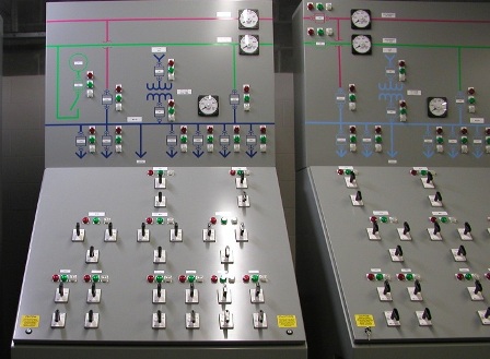
A special place in production program POISK companies occupy control panels for such facilities as hydroelectric power plants, nuclear power plants, thermal power plants, state district power plants..., called Main control panels (MSC) or Central control panels (CPU). Such shields, in addition to a fairly developed mnemonic diagram, also contain various controls, as well as a large number of measuring/recording instruments and digital indicators. Most often, main control room/central control boards are emergency (critical) means of control over the object, therefore many display and control elements on them have direct connections with the equipment they control. Such shields are subject to special requirements by design, information content, complexity and reliability.
A variety of control panels are those produced by the company POISK built-in mosaic consoles and control and display panels. Such panels usually have small size(no more than 2 sq.m.) and are designed for installation in consoles or operator/dispatcher tables.
POISK-SHIELD technology allows you to create control panels ranging from very simple passive (without LED indication and control system) wall panels less than 1 sq.m in size, to big complex ones active boards (mnemonic visualization complexes) with an area of 100 square meters or more, with a large list of options, equipped with video panels or built-in video walls, extremely rich in electronic mnemonic symbols and indicators, and also allows you to create video boards (video walls).
The POISK company is always focused on fulfillment full cycle works, covering all stages - from technical consultations and design, to installation and commissioning with training. At the same time, to reduce the cost, it is possible to order any set of components for self-assembly board or video wall, as well as any amount of work from the full cycle.
In production video board(video walls) the POISK company, unlike its competitors, offers the customer the full range of services necessary for the full operation of the product (this is enough a rare combination that allows you to get started right away with video board):
- professional selection, production and supply of a set of video board equipment (hardware), its assembly and commissioning (including training),
- supply of specialized ZNZ dispatch software of its own design (software part),
- content software part - creating an electronic mnemonic diagram (or a complex multi-layer project) of the customer’s network in the ZNZ dispatch software, as well as configuring it and performing the necessary initial settings.
The POISK company has been operating in the electricity market since 1993 and has unique experience in designing more than 400 mnemonic circuits various types for all types of electrical networks, as well as other mnemonic diagrams. The work cycle offered by the company includes multi-stage sequential approval electronic mnemonic diagram with the customer during the execution of work, which eliminates the possibility of obtaining a negative result at the stage of acceptance.
All along life cycle of control panels and video boards (video walls) produced by SEARCH them accompanies ZNZ dispatch software– developed by the company POISK.
The SEARCH company has necessary fleet of modern technological equipment, and own production facilities, providing POISK-SHIELD technologies with flexibility, adaptability and versatility, as well as allowing the development and production of original structural elements, incl. corresponding to the individual wishes of the customer.
Just look at the photos of our billboards/video walls to see how diverse they are. Using various techniques of the POISK-SHIELD technology, we give an individual look to each product, but at the same time, the features of corporate style. When you see our billboard or video board, you will always recognize it as a product of the POISK company - a clear, expressive, bright, contrasting mnemonic diagram, high information richness, a lightweight elegant frame, a thoughtful, fully finished design adapted to a specific room, modern finishing materials...
POISK-SHIELD technology provides the highest combination of price, quality and functionality control panels and video walls produced by SEARCH, which is confirmed by the number of orders we have completed.