Sewing machine veritas zigzag instruction. Sewing machine "Veritas": description, instructions and reviews. Inspection of the machine by a mechanic. Identified, preliminary, violations
Read also
For home? The company "Veritas" offers customers many models. Devices for beginners in the assortment of the company are also available. Shuttles are most often used of the drive type. For overlock fabric stitching, the devices are great.
In the standard set of cars, the user can find many paws. Even in stores there are models with belt shuttles. Power on average is no more than 50 watts. Devices differ greatly in speed of embroidery. A quality model costs no more than 23 thousand rubles.
Choosing a quality model
How to choose a sewing machine for your home? If you select a device for a beginner, then the power should be no more than 55 watts. It is more expedient to select a shuttle of a drive type with a protection system. The presser foot feeder must be located in the upper part of the body. Some models have a felt pad. Today they are in great demand. A device for pulling fabric deserves special attention. As a rule, it is used with a regulator.
Instructions for using the machine
First of all, you should choose a foot for work. Presser foot pressure dial should be in the up position. The embroidery speed is set by the regulator. The thread cutter must be open. Also, before work, you should check the needle threader.
Model description VERITAS FL-4034
VERITAS FL-4034 is a good quality sewing machine that comes with a powered hook. In this case, the needle threader is used with a regulator. According to customer reviews, the paws are of high quality. The stitch width can be adjusted if necessary. The bobbin for the sewing machine is made of aluminum. The lining above the shuttle is not provided by the manufacturer. For beginner seamstresses, the model is great. However, it is important to note that the thread cutter takes some getting used to. The stand is fairly compact. There is a loop for direct firmware.
If desired, the thread cutter can be cleaned independently. Decorative stitches can be done with a regular bobbin. Pulling the fabric from the machine of this series is very fast. The maximum embroidery speed is 320 lines per minute. The machine does not have a free sleeve. The automatic winding device is used mechanical type. Spare parts for sewing machines can be purchased at the service center. There is no bobbin for overlock stitches. You can buy this machine in the store for 27 thousand rubles.

Opinions about the device VERITAS FL-4050
VERITAS FL-4050 is a sewing machine for beginners, which features a high hook. In this case, the stand is made entirely of plastic. According to customer reviews, the needle threader is used with a quality screw. The bobbins of this model are rarely twisted. If necessary, the needle can be changed quickly. The winding system is provided by coil type. The stand in the device is made of polymer. In total, the model has three
For the purpose of direct stitching with a needle, the device fits perfectly. The fabric feed mechanism is used with a rail. The speed of embroidery on the machine is quite simple to adjust. The power of this model is 36 watts. In terms of dimensions, the device is compact and weighs very little. The stand is made entirely of plastic. The fabric tension regulator is not provided by the manufacturer. If we talk about the cons, it is important to mention a weak conveyor. If the machine is used incorrectly, the rail can be damaged. In our time, the model costs about 24,600 rubles.

Customer reviews of VERITAS Rubina
The Veritas Rubina sewing machine is in great demand. Buyers first of all choose it for an excellent shuttle. In this case, it is used drive type. It has an anti-jamming system. For short lines, the model fits well. The threader is of the screw type. The control panel is of high quality. For the purpose of zigzag stitching of fabric, the machine is often used. The feed mechanism is made with guides.
The sewing machine bobbin is made of aluminium. According to customer reviews, the tension regulator breaks very rarely. The embroidery speed is quite easy to adjust. The straight stitch feet are included. The conveyor in this case is made of plastic. The tanker is standardly located in the upper part of the hull. The loop of the model is provided with a bobbin. This machine weighs only 5.8 kg. You can buy it in the store at a price of 25,300 rubles.

Characteristics of the VERITAS HZ-911X model
This sewing machine "Veritas" has a lot of advantages. First of all, it is important to note that the model is great for beginners. Among the features of the modification, it is necessary to mention an interesting design. The shuttle is standardly used drive type. The stand under it is made of plastic. According to customer reviews, problems with the threader are rare. Its screw is of small diameter.
The sewing machine cutter is located in the upper part of the body. Presser feet for straight stitching are included as standard. For the purpose of longitudinal firmware, the device fits perfectly. The lining under the loop is made of plastic. The maximum embroidery speed is 330 lines per minute. The stitch length of the model is very easy to adjust. The bobbin for the overlock line is not provided in this case. The motor power of the machine is 56 watts. Her power consumption is negligible. A brush is used to clean the model.
Feedback about the device VERITAS HZ-915X
VERITAS HZ-915X is a good sewing machine that comes with one regulator. The loop in this case is located near the shuttle. The cutter is of the screw type. According to customer reviews, adjusting the embroidery speed is very easy. The paws in this case are made quite well. The motor power of the sewing machine is 45 watts. The fabric fastening mechanism in the device is installed in the upper part of the body. The feed box is made with a rail. The overlock stitch foot is included as standard.
For the purpose of zigzag stitching, the model fits perfectly, but it is important to note that it does not have a conveyor. The threader is made of plastic. A loop is used for double stitching. The threading mechanism is located under the hook. The stand for it is made of small height. Bobbins for straight stitching are included as standard. The needle can be quickly changed if necessary. This Veritas sewing machine is for sale at a price of 29 thousand rubles.

Customer reviews of VERITAS 8014
The sewing machine "Veritas 8014" is very popular among beginners. First of all, she is praised for her high-quality threader. The cutter is normally used with a screw. In total, the model has two straight stitch legs. The coil regulator is made of plastic. In order to carry out overlock work, the model fits perfectly. However, it is important to remember that she does not have a conveyor. The rail in the standard set includes a small length.
For the purpose of stitching the skin there is a special bobbin. The feeder is located behind the hook. The maximum embroidery speed is 380 lines per minute. A directional seam foot is provided. The lining in the kit is of a polymer type. You can buy the specified sewing machine at a price of 23,600 rubles.
Features of the VERITAS OS-2016 model
This sewing machine "Veritas" is manufactured with a drive shuttle. The cutter for this model is located above the stand. Coils in this case are used with caps. This sewing machine weighs only 6.5 kg. Bobbins for direct sewing of fabric are included in the set. It is also important to note that the model is ideal for overlock work. The needle in the holder changes without problems. Special attention deserves a quality transporter. The rake for him is selected for a small length. If necessary, the cutter can be quickly removed. The foot is made of plastic. There are bobbins for overcasting stitching.
Also in the kit, a set of needles is attached to the device. The shuttle regulator is of high quality. The winding system is of a mechanical type. The gasket in this case is under the rack. The maximum embroidery speed is 420 lines per minute. The bobbins are attached above the holder. The guides are installed under the shuttle. For sewing zippers, the model fits perfectly. Also, a sewing machine of this series is recommended for working with leather. You can buy a model in our time at a price of 33 thousand rubles.
What they say about the VERITAS OS-2024 device
VERITAS OS-2024 is a sewing machine for beginners that comes with two spools. Her caps are closed type. If you believe the reviews, then the embroidery speed of the model is at a high level. There is a loop for direct stitching. If necessary, there is an opportunity to engage in overlock work. The guides of the model are made of plastic.
The needle holder is used with a small diameter. The threader is normally located under the hook. For longitudinal firmware, the model is used quite often. The feed mechanism is made with a screw. Motor power is 45 watts. The sewing foot is made of polymer. The minimum stitch width is 4 mm. Spare parts for sewing machines can be bought at the service center. The described model costs about 27,200 rubles.

One of the legacies of the past Soviet era is the Veritas sewing machine, made in the GDR (Germany). Like other sewing equipment of the GDR, the models of these machines are quite reliable in operation and durable. If you have such a sewing machine, do not rush to send it to the scrap. Veritas sewing machines (not all models) have a double-fit rotary hook used for industrial machines, and this is already a sign that the Veritas machine can sew quality stitches. The swinging sewing shuttle, of the same type as the Chaika sewing machine, is used only in inexpensive, economy-class models of modern sewing machines. Some models of Veritas sewing machines sometimes have an oscillating sewing hook, but most often, a rotating vertical hook is installed.
Repair of Veritas sewing machines is sometimes complicated by the lack of instructions and spare parts, since spare parts for sewing machine models from 81-91. they just don't release it anymore. Besides, the GDR is long gone. Therefore, there is simply nowhere to buy them, except at the "flea" market. However, the reviews of almost all owners of Veritas sewing machines are only positive. Therefore, if the machine needs repair, try it, maybe you can do a small repair of the Veritas sewing machine with your own hands.
1. Rotary hook of the Veritas sewing machine

The Veritas sewing machine is a complex zigzag machine, that is, it makes various types of stitches based on a zigzag stitch. The shuttle stroke is the same as that of the 97 class industrial machine and rotates in a vertical plane, which increases the accuracy class of the needle and shuttle, but subject to a good setting of the shuttle assembly.
Transfer from the main shaft to the lower shaft of the sewing machine is carried out using a woven nylon belt. This reduces noise when running at high speeds.
The shuttle is seated on a round axis and secured with screws. If they are loosened, the shuttle can be removed, which means it is convenient to adjust the gap between the needle and the nose of the shuttle.

Sometimes a broken thread gets into the shuttle, and then it stalls, the machine jams. In this case, the only correct solution is to remove the shuttle from the axle. To do this, tilt the machine on its side and on the right side, loosen the two screws securing the drive gear on which the belt is put on, then remove the fixing plate. It holds the bobbin holder of the shuttle. Now you can rotate the shuttle and loosen the screws that secure it to the axle. After removing the hook, unscrew the three screws securing the lock plate, the nose of which faces the thread hook (hook nose). Then moisten the joint with solvent and try to remove or turn the hook bobbin holder. On his belt there are six slots that need to be cleaned. Slots must always be kept clean. Assemble the shuttle in reverse order.
Attention! With inept disassembly of the shuttle, you can break its locking ring, which locks the bobbin holder. Be careful!
2. Veritas can sew jeans and knit fabric

The sewing machine "Veritas Rubina", in addition to excellent performance, also has a completely modern look, is equipped with an electric drive and can perform many different types of stitches. It is quite functional, that is, it is enough to put a special needle for denim fabrics and it will be possible to hem jeans. And if you put a needle for sewing knitted fabrics, then you can sew knitted clothes with high quality.
Veritas is a good household sewing machine, especially when compared to old models of Soviet sewing machines. And even the old models of Veritas, with a curbstone and a foot drive, can perfectly sew modern knitted fabrics. If you have an instruction manual for a sewing machine, then it is written in detail what fabrics can be sewn on Veritas, which sewing needles to use. How to select threads and needles, depending on the thickness of the fabric, threads and much more.

The Veritas sewing machine is equipped with a TUR-2 brand electric drive. This engine is of very good quality. For many years of using these drives in our practice, none of them "burned out", did not break, and even the brushes did not have to be changed even once. There are several engines that "sat down", that is, during prolonged operation they lose power and speed, but they work!
The TUR-2 brand electric drive can work for many years without requiring repair or replacement of brushes, even with intensive use of the sewing machine. But, like all electric motors for household sewing machines, it must work intermittently. Approximately half an hour of continuous work and a 10 - 15 minute break. This is especially important not to forget when processing curtains that have a large footage.
When working for a long time without interruption, a specific smell of burnt electrical wiring appears. This means that it has overheated and needs to be cooled down. Of course, the engine will not break down right away, but over time, due to frequent overheating, it will lose power, and the machine will work more slowly.

Another detail in the Veritas sewing machine that you should pay attention to is the sewing pedal. The sewing pedal often breaks at the Veritas sewing machine. And not so much because of an unsuccessful design, but because of a careless attitude towards it. The body of the pedal is very fragile and the upper part is fixed to a small protrusion of the lower part. Often this protrusion breaks on impact or strong pressure and the pedal "opens".
This breakdown can be eliminated on your own if you restore this limiter. But first you need to disassemble the pedal. In order to disassemble the pedal, it is necessary to pull out the metal rod connecting both parts of the pedal base. This bushing is fixed with a screw in the lower recessed hole, which is usually sealed and therefore it is difficult to see that there is a screw there.
And yet, after self-repair, do not leave the pedal plugged in, because the pedal from the inept adjustment of the rheostat can be constantly on, overheat and cause big trouble.
4. Electric drive belt and main shaft toothed belt

If the electric drive strap of the Veritas sewing machine is cracked or torn, you can definitely replace it yourself. To do this, loosen the fastening of the electric drive to the sewing machine. Next, slide the drive towards you, the belt tension will loosen, and remove it. Replace belt and tension.
The tension of the belt should be set so that when you press it with your finger, it flexes slightly. If the belt is too tight (tightened), the sewing machine will make more noise, and a tight move will appear.

The toothed belt is installed on almost any household old model of Veritas sewing machines. Thanks to this, the machine is noticeably quieter than Chaika, but there is a drawback. This belt tends to stretch and then the machine can be scrapped, since it is impossible to buy a new such belt.
5. Veritas Shuttle Clearance Specifications

If you decide to repair your Veritas sewing machine yourself (which is not recommended), you should learn how to adjust the position of the needle, since moving the needle forward is the cause of its breakage, and moving towards the seamstress is the cause of skips. And the wrong position of the needle in relation to the nose of the shuttle is the cause of almost all stitch defects in the sewing line.
First set the gap between the hook and the needle in the plane of rotation of the hook. This gap on the right prick of the zigzag of the Veritas sewing machine should be in the range of 0.1-0.05 mm. You need to adjust by shifting the shuttle along the axis of its attachment. The shuttle is attached with two screws.
The distance between the hook and the needle when it is in its lowest position is determined by the center angle of rotation of the hook. The beginning of the upward movement of the needle should begin no later than the moment when the hook nose and the needle form an angle of 45 degrees, and the straight line from the needle to the hook nose is 7 mm. At a smaller angle, there will be gaps on the right prick of the zigzag, at a larger angle, the upper thread will loop and break.
You need to adjust the gap by turning the shuttle on the axis (shaft) with the screws of its fastening loosened. If there are skipped stitches on knitted fabrics with the right zigzag injection, you can increase the central angle of rotation to 50 °. But at the same time, be sure to check if the line below has deteriorated. If the bottom stitching pattern has begun to be lost, and the upper thread is clearly visible from below, reduce the central angle to a size that improves the bottom stitching.
The moment of the meeting of the nose of the shuttle with the needle on the left prick of the zigzag. The distance between the lower edge of the nose and the upper edge of the eye is zero (pos. a), and on the right prick of the zigzag it is 2 mm. You need to adjust this parameter by moving the needle bar vertically and turning the shuttle.
The opinion of the master about which sewing machine is the best. Details about the used Rubin sewing machine and other old Veritas models.
The Veritas foot-operated sewing machine can be equipped with an electric drive with a pedal. It is not difficult to do this, since the machine has a standard mount for the electric drive. If you need to repair the foot drive, you can use the tips from this article.
The shuttle run of the Veritas double-fit sewing machine is the same as that of industrial lockstitch machines. But, nevertheless, its device has its own characteristics. However, many of the settings for the interaction of the hook nose and the needle, posted in this article, will also work for the Veritas sewing machine.
Lubrication of the sewing machine Veritas, Veritas Rubina and other models of machines from this company requires a lot of attention. Carefully study the instructions, read where you need to lubricate the machine, or independently determine all the rubbing nodes of the sewing machine and regularly lubricate them with a small amount of oil. Too much lubrication can only hurt.
This model of an industrial sewing machine, as well as the Veritas household sewing machine, was produced in the GDR. It is designed for sewing light and suit fabrics. For small sewing workshops and ateliers engaged in tailoring outerwear, the machine is simply irreplaceable. The presser foot advance mechanism together with the rail allows the machine to perform many specific operations, such as fitting the sleeve when sewing into the armhole, etc.
Repair of the sewing machine will not be required for many years if the machine is taken care of and taken care of. Periodically, you should clean the shuttle compartment from lint and thread residues with a stiff glue brush and lubricate the machine.
Elements of maintenance by the sewing machine SuperProgramAutomation
| 1 | Flywheel | 18 | Thread guide |
| 2 | Winder stop | 19 | Screw for fixing the needle |
| 3 | Winder spindle | 20 | Machine class designation |
| 4 | Coil rods | 21 | Top Tension Adjuster threads |
| 5 | 5. Thread pretension dial | 22 | |
| 6 | Thread guides | 23 | Pattern selection knob |
| 7 | Sleeve cover | 24 | Program switch knob |
| 8 | Eye of the thread take-up lever | 25 | Making switch loops |
| 9 | Light switch | 26 | shift lever |
| 10 | front cover | 27 | Sample table |
| 11 | eye for thread | 28 | Stitch length dial |
| 12 | Presser foot screw | 29 | reverse shift lever stitch progress |
| 13 | Presser foot | 30 | Conveyor lower lever |
| 14 | needle plate | 31 | sight glass |
| 15 | sliding plate | 32 | Flywheel freewheel screw wheels |
| 16 | Conveyor | 33 | Index letters and number cars |
| 17 | Needle |
Attention!All necessary work on the electric sewing machine, such as: changing the needle, changing the presser foot, changing the V-belt, threading, etc., should be carried out only after removing the foot from the ballast, so that in case of accidental movement of the foot, do not start the machine in action
General instructions
2. Basic Rules
Turn the flywheel towards you only.
- Be sure to lower the presser foot before sewing.
-Start the machine with thread only with fabric under the presser foot.
- Do not pull or move the fabric while sewing.
- In the non-working position of the machine, the switching of levers and buttons can be carried out if the needle is raised above the fabric.
-Make sure the machine is clean and lubricated regularly (also lubricate the machine before sewing for the first time).
- Before and after sewing, each time raise the thread lever 8 to the highest position. This will prevent the thread from being pinched, and besides, the finished work can be removed more easily.
- Make sure that the feed dog lower lever 30 is moved to the right side for sewing (section 15)
3. (Fig. 2)
Needles apply system 705 or 130.
By turning the handwheel, the needle is set to its highest position. Then the fixing screw is unscrewed and the needle or the rest of the broken needle is removed.
A new needle is inserted with the left hand. Turning the flat side of the thickened part of the needle back, the needle is inserted into the needle holder and into the slot of the rod until it stops. Then tighten the screw to secure the needle.
The thread groove on the needle is located at the front. The thread is threaded into the needle from front to back. Inserting the needle incorrectly or not up to the end stop causes thread breakage and skipped stitches.
4. Needle and thread
In addition to the correct thread tension, it is necessary to match the thickness of the needle, thread and fabric being sewn. Very thin needles break when sewing thick fabrics and using thick threads. Thick needles make large punctures in thin fabric and impair the appearance of the stitch. When skipping stitches and thread breakage, the needle is changed to a new needle, the number of which corresponds to the thickness of the thread (section 3).
Mismatched, crooked and blunt needles create unsightly seams, skipped stitches and thread breaks.
Do not allow the bottom thread to be thicker than the top thread.
The thickness of the lower thread must match or be thinner than the thickness of the upper thread.
5. Turning the sewing mechanism on and off
The sewing mechanism is turned on by turning the screw disk 32 in the direction of the arrow "b". At the same time, the flywheel 1 is held with the left hand (Fig. 3).
To wind the thread on the bobbin, the sewing mechanism is turned off. To do this, hold the flywheel with the left hand, and turn the screw disk with the right hand in the direction of the arrow "a" (Fig. 3)
6. (Fig. 4) 
By turning the handwheel, the thread take-up lever is set to its highest position. Then the sliding plate 15 is pulled out and the latch 47 of the bobbin case is opened through the hole in the platform with the thumb and forefinger of the left hand and the bobbin case with the bobbin is removed (Fig. 4).

Winding the thread on the bobbin is done with the sewing mechanism turned off.
After turning off the sewing mechanism (Fig. 3), a spool of thread is put on the spool pin 4. The end of the thread unwound from the spool is circled around the thread guide 5 and under the clamp to create thread tension. bobbin put on spindle 3 and turn until entering spindle pin into the groove of the bobbin. After winding the thread several times on the bobbin, the winder is pressed against the flywheel. As soon as the bobbin is wound, the winder automatically turns off. The winder is wrung out and the bobbin is removed. To form a regular and beautiful seam, it is advisable that the lower thread is slightly thinner than the upper thread.
8. (Fig. 6)

On the cover of the arm of the sewing machine there are two spool pins 4, which, if not needed, can be installed in a horizontal position. For coil attachment, they are transferred to a vertical position.
Before lowering the top of the machine into the cabinet table, the spool pins must be rotated to a horizontal position.
9. 
A bobbin case with a closed latch is taken with the left hand so that a bobbin with a wound thread can be inserted into the open part with the right hand. The inserted bobbin should rotate from left to right (clockwise direction) when pulling the thread (Fig. 7)
Then the thread is pulled through the cut of the bobbin case under the tension spring until it exits the nose “a” (Fig. 8 and 9).
The thread can also be inserted into the hole in the end side of the bobbin case. It is advisable to do this when sewing with a zigzag stitch, when there are increased requirements for the quality of the seam.


10. Installing the bobbin case
To install the bobbin case, the flywheel 1 is turned until the thread take-up lever 8 is raised to its highest position.
For a beginner seamstress, it is recommended to insert the bobbin case by tilting the machine on its side.
With your thumb, press the bobbin case until the cap enters the latch. If the bobbin case is not inserted into the latch, it may cause needle breakage and other damage.
By turning the handwheel 1, the needle is set to its highest position.
The thread tension in the regulator 21 is loosened by raising the presser foot presser bar lift lever. The upper thread is threaded in the back and front thread guides 6, then it is laid between the two clamping washers of the tension regulator 21, then through the eye of the thread take-up lever 8, the thread eye 11 and the thread guide 18.Fig. ten
The thread is threaded into the needle from front to back. To start work, leave the free end of the thread behind a needle 10 cm long. To facilitate the threading of the upper thread, it is shown on the front cover. Rice. eleven


12.
The presser foot is designed as a stepped element. At the first stage, sewing is performed, as well as darning without a presser foot. At the second stage, the upper thread tension mechanism is turned off.
After raising the foot to the second step, the free end of the upper thread is taken with the left hand without pulling it. The flywheel is turned in the direction of the arrow (Fig. 1) one turn until the thread take-up lever 8 rises to its highest position. Carefully pulling the end of the upper thread, simultaneously pull up the lower thread (Fig. 12)
Both ends of the threads are laid under the foot on the back side (Fig. 13).


The stitch length knob 28 is used to set the stitch length for normal seams (fig. 14). Switch lever 29 is for reverse feed and normal seam stitching.
Knob scale 28 has numerical values for setting the stitch length.
If you want to get the same stitch length when sewing backwards as when sewing forward, then press switch 29 down as far as it will go (Fig. 14). The reverse stitch is only for securing the seam.
As a rule, you should:
Sew thin fabrics with a thin thread and a small stitch step. Thick fabrics with thread of the appropriate thickness and large stitching pitch.
Please note that the conveyor lowering lever 30 is moved to the right side (the “zigzag” symbol is visible on the lever button).
For extra elastic seams, the stitch length dial 28 is set to 4 mm (symbol ) This predetermines the stitch length for various seams and does not require intervention by the seamstress.
Attention!
When sewing with the symbol, the front and back stitches are programmed. In this case, do not move the stitch reverse switch lever.
14. Proper tissue management.
At the beginning and at the end of sewing, the thread take-up lever 8 (fig. 1) should be in the highest position. The fabric is placed under the foot to the needle, then the foot is lowered, the ends of the lower and upper threads are held with the left hand until a few stitches have been made. The fabric is automatically advanced by the machine.
In the process of sewing, the fabric cannot be pulled, you only need to slightly adjust it with your hands.
When pulling and pushing the fabric, the needle is bent or broken, which may cause damage to the sewing mechanism.
Hard places or thick seams should be sewn slowly by turning the handwheel by hand.
In such cases, it is recommended to raise the foot and move the fabric slightly. When sewing very thin fabrics such as silk, etc., it is recommended that you guide the fabric slightly behind the presser foot to prevent the seam from curling. Besides. it is advisable to put thin paper under the fabric.
If you want to sew sharp corners, stop the machine when the needle has risen to the thickness of a finger from the bottom position. Then raise the presser foot, turn the fabric on the needle in the desired direction, lower the presser foot and continue sewing.
The finished work is taken out in the following order: the thread take-up lever 8 is placed in its highest position, the foot is raised and the finished fabric is pulled back. In order not to bend the needle, the thread should slide easily under the foot back.
To form a seam, the feed dog must not be lowered and the stitch length dial must not be set to zero.

Presser foot pressure should be adjusted according to the type of fabric. Thin fabrics require less force to press than thick fabrics. The pressure of the presser foot on the fabric should be such that uniform advancement of the fabric is ensured, and the needle would not grab the fabric during its upward stroke.
To adjust the degree of presser foot, remove the front cover (section 27). When the adjusting screw is turned to the right, the pressure increases and when it is turned to the left, it decreases (Fig. 16).

To replace the foot, the needle is set to the highest position and the rod with the foot is raised. Then the fixing screw is unscrewed to such an extent that the presser foot can be removed obliquely down (Fig. 17).
18.
On the front side of the machine there is a plate with stitch patterns 27, which shows decorative and work stitches. Separate samples of seams are indicated by digital indicators. On the cover of the sleeve 7 there is a switching lever 26, which moves in the direction of the slot. In accordance with the desired seam, the shift lever is installed in the appropriate direction, forward (toward) or backward (away from you).
The central selection knob will make it extremely easy for you to set the various seams (stitches). With the program selector knob 24 (fig. 18) you select the appropriate program “normal”, (elastic) or “loop” and then select the desired stitch with the pattern selection knob (fig. 19). When doing this, make sure that the shift lever 26 is moved in the direction of the desired seam (forward or backward).
When turning on the program switch and pattern select knobs, note that both knobs have settling endpoints that cannot be switched through.
Do not turn on the handles and levers when the needle is still in the fabric.
Attention!Select a medium sewing speed (600 - 800 rpm) for seams with the symbol.


19. Thread tension adjustment
BUT)
The factory-set thread tension is suitable for various thread numbers and sewing applications. In this regard, it is recommended to familiarize yourself with the degree of thread tension by touch. To do this, take the bobbin case with your left hand, and pull the thread out of the cap with your right hand. Thus, they feel what the thread tension should be.
A slight change in the thread clamp is carried out using the spring screw (Fig. 20)
Turning the screw to the left decreases the pressure of the spring on the thread. When the screw is turned to the right, the pressure of the spring on the thread increases. 

Dear buyer!
Class 8014/43 will be equipped with two options for top thread tension.
Depending on the variant, refer to the description of the mechanism for tensioning the upper thread B or C.
B) (Fig. 21)
Turning the knob to the right (clockwise) will increase the upper thread tension, and turning it to the left will decrease it.
The tension of the upper thread for all sewing jobs is achieved with one turn of the knob, on which there are digital marks from 0 to 9.
0 to 2 light tension (e.g. for buttonholes, decorative seams, embroidery).
3 to 6 normal tension
7 to 9 reinforced tension.
C) (Fig. 22)

The upper thread tension is adjusted by turning the knob. Turning to the right (in the direction of the + arrow) increases the tension. Turning it to the left (in the direction of the - arrow) will decrease the thread tension. In order to quickly and coarsely set the thread tension, there is a jumper with a red marking between the tension housing and the thread tension knob.
The edge of the handle should be placed on this marking in order to finally adjust the tension of the upper thread after sewing the control seam.
Correct straight line
- Set the pattern selection knob 23 to 4.
- Set the program switch lever to "normal"
The quality of the stitch depends on the correct adjustment of the thread tension. For control, sew a row of seams and check the tension of the upper and lower threads.
The interlacing of the upper and lower threads should be in the middle of the fabric (Fig. 23a)
If knots and loops form on the underside of the fabric, this is a sign that the upper thread tension is not enough or the bobbin thread tension is too high (fig. 23 b)
If the formation of knots and loops occurs on the upper side of the fabric, then this is a sign of excessive top thread tension or low bobbin thread tension (fig. 23 c) 


If loops and knots are formed alternately on the top and bottom sides of the fabric during sewing, it means that the tension of both threads is not enough. It is also impractical to set a very high thread tension, as this may cause thread breakage, especially thin threads.
On very thin fabrics, loops of upper and bobbin threads form on both sides of the fabric.
20. Sewing instructions
1. Stitching fabrics folded in two layers.
1.1. Seams for normal load
a) (Fig. 24)
Set shift lever forward
Program switch knob
set to "normal".
Stitch length 1.5 4 Straight stitch foot N° 511 (Order N° 84 00 37 31)
The straight stitch is used for sewing fabric folded in two layers.
b) stitching zipper(Fig. 25)
Shift lever set back
Stitch length 2 - 3
This stitch allows you to sew two layers of fabric and overcast at the same time. Two pieces of fabric are tucked under the foot so that four straight stitches sew the fabric, and one side stitch sews outside the fabric at the very edge, the resulting loops protect the edge of the fabric from fraying. This stitch can also be used to overcast the edge of fabric. With a very short stitch length, the zipper stitch is an elastic stitch.


in) ![]()

Set the program switch knob to "normal"
Stitch length 1 - 2
The edges of the fabric are laid one on top of the other and sewn with a feathery stitch.
G) Knit stitch good flat stitch for knitwear![]() (Fig. 27)
(Fig. 27)

Set shift lever back
Program switch knob
set to "normal" Stitch length approx. 1
When sewing with this seam, the edges of the fabrics overlap one another by 5 mm and are sewn together.
1.2. Seams for highly stretchy material rice. 27a
a) Home overlock ![]()

Set shift lever back
Set the pattern selection knob to 3
Zigzag foot No. 34
Elastic straight stitch with overcasting is used as a zipper stitch for stretch fabrics only
b) Herringbone stitch(Fig. 28) 
Set shift lever back
Set the pattern selection knob to 7
Set the program switch knob to the symbol
Set the stitch length dial to
It is necessary to put two parts of the material to each other in a joint and sew them together with a herringbone stitch. And with normal stitching, the herringbone stitch is a very elastic stitch.
c) (Fig. 29) ![]()

Set shift lever back
Set the pattern selection knob to 6
Set the program switch knob to the symbol
Set the stitch length dial to
Zigzag foot No. 534
It is used for stitching with simultaneous overcasting of the edge. It is a flat, very elastic seam. When sewing with this seam, the edges of the fabric are superimposed on one another by 5 mm and sewn together.
Application area:
- for edging tablecloths
- for sewing on a rubber band
- for stapling and overcasting at the same time
- for decorative stitching
d) (Fig. 30) ![]()

Set shift lever back
Set the pattern selection knob to 4
Set the program switch knob to the symbol
Set the stitch length dial to
Zigzag foot No. 534
Very elastic seam. This stitch is especially suitable for knitwear, with intermediate stitches strengthening the stitch density.
Application area:
for edging knitwear
for sewing knitwear
for decorative stitching.
e) Additional adjustment of super elastic seams
When using different qualities and thicknesses of the fabric, it is possible to install super-elastic (reverse) seams, depending on the fabric used. This additional adjustment is very simple and can be done by every housewife.
This requires the following steps:


c) (Fig. 30a) ![]()
Set shift lever back
Set the program switch knob to "normal"
Stitch length 2
Zigzag foot N° 534
The arc seam is used for stitching elastic knitted and knitted products. Since this seam is elastic and decorative, it is used for sewing on lace.
Attention! The shorter the stitch length, the more elastic the seam.
The arc seam is suitable for stitching parts into a joint.
These parts are sewn together with a few stitches and a reliable connection is formed.
By superimposing a zigzag stitch on an arc stitch, it is possible to lengthen, for example, children's clothing, and in a beautiful way.
1.3 Seams for special loads
a) Triple reinforced secure stitching(Fig. 31) ![]()

Set shift lever forward
Set the pattern selection knob to 4
Set the program switch knob to the symbol
Set the stitch length dial to
Zigzag foot N° 534
A particularly hardy seam that is used where a normal seam would break, such as sewing on pockets and sleeves and sewing trousers.
b) (Fig. 32) 
Set shift lever forward
, 2 or 3
Set the program switch knob to the symbol
Set the stitch length dial to Zigzag foot N° 534
These seams are especially strong and have high elasticity.
c) (Fig. 33) ![]()

Set shift lever back
Set the pattern selection knob to 2
Set the program switch knob to the symbol
Set the stitch length dial to
Zigzag foot No. 534
Very elastic and durable stitching with reinforcement stitches. Suitable for sewing trousers and sportswear.
G) Herringbone stitch(see fig. 28)
Set shift lever back
Set the pattern selection knob to
Set the program switch knob to the symbol
Set the stitch length dial to
Zigzag foot N° 534
The seam is very elastic. It is used for durable stitching of fabric, for example, when sewing skirts and children's clothing. It is necessary to put two parts of the material to each other in a joint and sew them with a herringbone stitch with a simultaneous decorative effect.
e) Stitching for pockets
Set the pattern selection knob to 1
Set the program switch knob to "normal"
Set the stitch length knob to
Feed dog lowers Zigzag foot No. 534
After the usual sewing of the pocket, for special reinforcement, bartacks of 15 to 20 stitches are sewn on the edges. Emblems can also be sewn on.
2.
a) zigzag stitches (Fig. 34)
Set shift lever forward
Set the program switch knob to "normal"
Stitch length 1 - 3
Zigzag foot N° 534
These seams are strong and elastic. When a very strong seam is not required, a wide zigzag stitch can be used. In this case, set the pattern selection knob to 1, stitch length 13.

b) zipper stitching(Fig. 34a) ![]()
Set shift lever back
Set the pattern selection knob to 3
Set the program switch knob to "normal"
Stitch length 2
Zigzag foot No. 534
The overcasting fabric is tucked under the foot so that the straight stitches are sewn past the edge of the fabric and the zigzag stitch is sewn through the fabric. This stitch is used when sewing trousers.

c) (Fig. 35) ![]()

Set shift lever back
Set the pattern selection knob to 5
Set the program switch knob to the symbol
Set the stitch length dial to
Zigzag foot N° 534
This stitch is especially suitable for overcasting the edge of a fringed fabric. Intermediate stitches reinforce the fabric well.
G) knit stitch ![]()
Set shift lever back
Set the pattern selection knob to 6
Set the program switch knob to "normal"
Stitch length 1.5 - 2
Zigzag foot N° 534
Overcasting fabric is tucked under the foot in such a way that straight stitches are sewn alternately in the fabric, then past it at the very edge.
3. Sewing buttonholes(fig. 36 - 41)
Set shift lever forward
Set the pattern selection knob to 5
Set the program switch knob to "loop"
Set the switch for making buttonholes in the direction of the arrow upwards.
Set the stitch length knob to the buttonhole symbol.
Buttonhole foot N 771
To sew buttonholes, the pattern selector must be set to "5". The program switch knob is set so that the “loop” symbol is at the top (Fig. 36).
Now you need to move the switch for making loops 25 in the direction of the arrow up. At the same time, the knobs for switching the program and selecting patterns are firmly connected to each other (Fig. 36). Now both knobs turn on together. 


The sequence of working strokes (the position of the control knobs is shown in the figures):
1.
Sewing the right side of the buttonhole (fabric moves back) - bring the needle to the top position.
2.
Sewing the first bartack - bring the needle to the up position
3.
Sewing the left side of the buttonhole - bring the needle to the top position
4.
Sewing the second bartack
Remember to move the buttonhole switch to its original position after sewing the buttonhole.
4. (Fig. 42) ![]()

shift lever set back
Set the pattern selection knob to 1
Set the program switch knob to "normal"
Set the stitch length dial to
The conveyor is lowered
Button sew-on foot No. 291
Buttons, hooks, buttonholes and press studs can be easily sewn on with the button sew-on foot. The button is placed under the foot so that the holes of the button are within the opening of the foot. The needle should, in the left position, pierce in the center of the left hole and in the right position, pierce in the center of the right hole of the buttons. After starting the machine, sewing on a button and securing the thread is carried out automatically.
If the button has more than two holes, then for the next two holes, the button is rearranged and stitched in the order indicated above.

a) Narrow hem in linen(Fig. 43)
Set the pattern selection knob to 4.
Set the program switch knob to "normal"
Chopper foot No. 111
Before proceeding with the practical application of the undercutter, it is advisable to familiarize yourself with it first.
The hemmer is suitable for thin to medium thickness fabrics and is good at hemming obliquely cut fabrics. The needle is raised to the maximum height and the presser foot is replaced with a hemmer.
Raising the lower thread up, it is laid together with the upper thread under the hemmer back.
Before starting the hem, the corner of the fabric should be cut obliquely so that the fabric can be wrapped more easily in the hem.
Then the fabric is folded with a width of about 6 mm and passed through the hole of the hemmer to the needle.
The hemmer is lowered and 23 stitches are sewn. Then the beginning of the hem, together with the ends of the threads, is slightly pulled back until the conveyor captures the hem well.
To obtain a smooth and even hem, the edge of the fabric is directed with the thumb and forefinger into the hem (Fig. 43), while it is necessary to adjust the width of the strip of fabric entering the hem. It is recommended that the fabric be slightly lifted when feeding.
The hemper is often used to hem handkerchiefs, towels, shirts, blouses, etc.
b) (Fig. 44)

Set shift lever forward
Set the pattern selection knob to 1
Set the program switch knob to "normal"
Stitch length 1.5 - 2.5
Zigzag foot No. 534
Bend the straight cut edge of the fabric to a certain width and sew with a zigzag stitch, as shown in fig. 44.
c) (Fig. 44 a)

Set shift lever forward
Set the pattern selection knob to 4
Set the program switch knob to "normal"
Stitch length by 2 - 3
Straight stitch foot No. 511
The guide ruler is used for seams that run parallel to the edge of the material (Fig. 44a). With a set screw, the guide ruler is fixed at the desired distance from the foot on the machine platform. The edge of the material runs along the guide ruler.
6. Darning and sewing on patches,

Set the pattern selection knob to 4
Set the program switch knob to "normal"
Stitch length 1.5 - 3
Zigzag foot No. 534
By sewing several three-stitch zigzag seams side by side in one place, you can darn frayed areas in clothes.
b) 
Set shift lever forward
Set the pattern selection knob to 4
Set the program switch knob to "normal"
The foot is removed, the conveyor is lowered. Cut out the damaged area and pull the fabric tightly into the hoop. Place the fabric under the needle and pull the bobbin thread up through the fabric. The presser foot lifter is lowered to tighten the upper thread. When the machine is running fast, the hoop is moved slowly and evenly back and forth with both hands in the direction of the threads of the fabric, leaving about 1 cm beyond the edges of the defective area. Then darn in the transverse direction.
c) (Fig. 47) 
Set shift lever forward
Set the pattern selection knob to 1
Set the program switch knob to "normal"
Stitch length 1.5 - 2.5
Zigzag foot No. 534
A patch is placed under the defective area, the size of which is larger than the rubbed area. The direction of the threads of the patch and the fabric must match. The patch is sewn along the edge. The corners of the patch are stitched twice for strength. After sewing on the patch, the damaged part of the fabric is cut out along the inner seam. The protruding edges of the patch are also cut off.
G) Sewing patches on knitwear(Fig. 48a, b, c)
Set shift lever back
Set the pattern selection knob to 4
Set the program switch knob to "normal"
Stitch length 1
Zigzag foot No. 534
This stitch is ideal for household chores such as:
- Sewing patches on knitwear.
- Sewing on a rubber band
- Stitching two pieces of material together.
A patch is placed under the defective area, the size of which should be larger than the worn area and the interweaving of the threads of which coincides with the fabric. The patch is basted with several stitches (Fig. 48 a) A seam is sewn along the basting and a second seam is sewn at a distance of about 0.5 cm (Fig. 48 b). The damaged part of the fabric is cut out along the inner seam (Fig. 48c). Then cut the edges of the patch along the outer seam and remove the threads used for basting.


7. Sewing on zipper and rubber bands.
a) Sewing on zippers(Fig. 49) 
Set shift lever forward
Set the pattern selection knob to 4
Set the program switch knob to "normal"
Stitch length as required
Edge foot No. 181
The edging foot is fixed on the machine. The foot is used for stitching narrow edges and for sewing on zippers (Fig. 49).
When sewing a zipper, the fabric is not stretched, but the zipper, on the contrary, is pulled.
b) Sewing on a wide rubber band
Set shift lever back
Set the pattern selection knob to 4 or 5
Set the program switch knob to "normal"
Stitch length 1 - 2 or 2 - 3
Zigzag foot No. 534 The elastic band is sewn to the fabric with a zigzag stitch without tension, so the fabric does not curl.
c) (Fig. 50) 
Set shift lever back
Set the pattern selection knob to 4
Set the program switch knob to "normal"
Stitch length 1
Zigzag foot No. 534
The fabric is laid out smoothly and the beginning of the rubber band is sewn on. The tape is then stretched as needed. After sewing, the rubber band shrinks and gives crimp to the fabric.
G) Sewing on a rubber cord
Set shift lever forward
Set the pattern selection knob to 4
Set the program switch knob to "normal".
Stitch length 23
Zigzag foot No. 534
The rubber cord is wound with a slight hand tension on the bobbin, as described in section 9, without changing the spring tension. By holding the bobbin, the rubber cord is stretched, as a result of which the rubber becomes thinner and easier to thread, and it is not passed through the hole in the bobbin case. The rubber cord is lifted up (see section 12), the fabric is laid under the foot and stitched. As a result, tissue curl occurs.
8. Patterns and decorations
a) (Fig. 51) 
Set shift lever forward
Set the pattern selection knob to 4
Set the program switch knob to "normal"
Stitch length approx. 3
Edge foot with ruler N«181 (order N° 84 00 36 21)
The screw-on guide bar makes it easy to sew parallel seams. The fabric is guided so that the ruler slides along the stitched seam. The second seam is stitched at a set distance. In this way, you can scribble rows and squares of the same width, as well as quilting cotton products. (Fig. 51). Cotton wool is laid between two layers of fabric and stitched evenly.
b) (Fig. 52)

Set shift lever forward
Set the pattern selection knob to 1, 2, or 3.
Set the program switch knob to "normal"
Stitch length 1 1.5
Zigzag foot N° 534
Fold the edge of the fabric 2 - 3 mm, lay the lace and sew it with a zigzag stitch.
in) 
Set shift lever back
Set the pattern selection knob to 5
Set the program switch knob to the symbol
Set the stitch length dial to 2
Zigzag foot N° 534
Depending on the desired length of the fringe, the required number of threads is pulled out of the fabric. In order to prevent the threads from shedding, the upper edge is sheathed with a cross stitch (Fig. 53). The seam looks very nice if the color of the sewing thread differs from the color of the fabric. Fringe decorate tablecloths, scarves, scarves, etc.
d) (Fig. 54)

The finishing hem can be sewn with knitting stitch, herringbone stitch, cross stitch or feather stitch. The border can be sewn by composing different stitches and combining them using the repeat indicator. This is how decorations of various clothes are made.
e) (Fig. 55)
Forward shift lever.
Set the pattern selection knob to 1, 2 or 3
Set the program switch knob to "normal"
Stitch length selectable 0.5 - 3
Zigzag foot N 534
Applications can be made in two ways:
Cut out patterns can be sewn with dense (minimum pitch) or wide (large pitch) zigzag stitches (fig. 55).
The applique is drawn on the fabric and sewn) along the lines of the pattern with narrow, short zigzag stitches.
Then the protruding edge of the applique is cut close to the seam and the appliqué is sheathed with wider zigzag stitches (with a minimum step) (Fig. 56). In this case, the tension of the upper thread must be loosened.


f) (Fig. 57)

When embroidering, as with darning, the presser foot is removed from the machine by unscrewing the presser foot screw. The conveyor is lowered. The presser foot lifter is lowered so that the upper thread is under tension.
Embroidery is darning to perfection and requires special confidence in the direction of the fabric.
The pattern is applied to the fabric. The fabric is hooped. The fabric is placed face up on the outer ring and then pressed firmly against the inner ring. The hoop with a stretched fabric and a pattern applied to it is brought under the needle so that the fabric lies directly on the needle plate. Putting the fabric under the needle, raise the bobbin thread. The hoop is moved by hand so that the needle makes injections according to the pattern. The hoop is moved with light and quick movements when the needle is out of the fabric.
21. Lighting
The sewing machine has a built-in electric lamp that provides good illumination of the sewn material. The light switch 9 is located on the front cover. The incandescent lamp has a screw base. To prevent malfunction of the machine, do not install lamps with a power of more than 20 watts.
Use 220 V/15 or 20 W finger lamps with E 14 base.
22. Care
If used frequently, the machine should be thoroughly cleaned once a week. Daily use of the machine requires daily lubrication.
Each bearing is lubricated with one or two drops of engine oil (Fig. 66.68).
The shuttle should also be lubricated.
Warning!
Use only special sewing machine oil for lubrication. Do not use grease or oil containing tar, as this will cause machine failure.
Do not oil the fabric belt.
Over time, dust and lint build up under the needle plate 14 and on the feed dog 16, which can make it difficult to feed the fabric and cause the machine to run rough. Unscrew the needle plate 14 (fig. 58), remove the dirt.
Between the teeth of the conveyor, contamination is removed with a wooden stick.
(Fig. 59). Do not use a screwdriver to do this, as this may damage the feed teeth and interfere with the fabric feed.


b) (Fig. 60)

In order to ensure smooth and trouble-free operation of the machine, the hook should be washed periodically with a few drops of kerosene.
All shuttles are tempered to the hardness of glass and are sensitive to impact and pressure with hard objects (screwdriver, scissors, etc.)
in) Bearing cleaning
If the machine has not been used for a long time, it may be difficult to move. This can be caused by oil gumming, dust and dirt. In this case, a few drops of kerosene are instilled into each bearing (Fig. 6668) and the machine is put into action until the kerosene flows out of the bearings. Then the bearing is cleaned of protruding dirt and lubricated with one or two drops of sewing machine oil.
The foot drive should also be periodically cleaned of contamination, as described in the previous section, and the bearings marked with arrows (Fig. 61) should be lubricated with machine oil.
Proper and regular lubrication ensures smooth and trouble-free running of the machine and increases the service life.

23. Electric motor for sewing machine
If your sewing machine is equipped with an electric motor, the sewing speed can be adjusted with the foot switch. The starter allows you to sew slowly or at high speed. The electric motor needs almost no maintenance, since its bearings are self-lubricating. Carbon brushes wear out after 650 hours of operation, at full motor load. With a slow sewing process, the temperature of the foot starter housing rises and, depending on the duration of operation, can heat up to 80 ° or even up to a maximum of 135 ° C. The heating of the foot starter is normal and does not adversely affect the motor and starter. If the belt is stretched out after a long period of work, then unscrew the motor mounting screw on the sewing machine arm a little and move the bracket together with the motor down to such an extent that the belt receives the necessary tension. The drive belt will be properly tensioned when the top and bottom of the belt between the motor and the sewing machine can be moved about 2 cm apart without much effort. It is not recommended to tighten the belt too much, because too much tension reduces the life of the belt and puts a lot of stress on the motor bearings.
If you wish to remove the machine from the machine cabinet, table, machine stand, tilt it backwards downwards. Using a screwdriver, unscrew both screws, as indicated by the arrow in fig. 62. Now you can release the machine from the hidden hinges.
When installing the machine, make sure that the machine goes up to the stop of the hidden hinges. Be sure to fasten both screws.

25. Troubleshooting Guide
|
Machine skips stitches |
|
|
Cause: |
Correction: |
|
The machine is incorrectly fueled |
See section 11 |
|
The needle is not inserted all the way |
Insert the needle as far as it will go, see section 3 |
|
Wrong needle system |
Replace with a 705 system needle or |
|
Wrong position inserted |
Flat side of the needle shaft |
|
Needle number unsuitable for |
See section 4 |
|
Dull or bent needle |
Insert a new needle, see section 3 |
|
Insufficient presser foot pressure |
See section 16 |
|
Upper thread breaks very often |
|
|
Cause: |
Correction: |
|
Needle plate hole |
|
|
Strong thread tension |
Loosen the thread tension, see |
|
Fragile and knobby thread |
Eat a better variety |
|
The thread has dropped off the spool and |
Wind the thread on the spool and rewind |
|
Wrong direction of rotation |
Correct direction of rotation |
|
Uneven stitching |
|
|
Cause: |
Correction: |
|
Weak top and bottom tension |
Take into account all instructions about the "pass |
|
Clamping discs are oiled and |
Clear Details |
|
Bobbin is twisted |
Insert new bobbin |
|
Dry or dirty hook |
Clean shuttle, see section 22b |
|
The bobbin is inserted into the bobbin stake |
See section 9 |
|
Uneven winding of the bobbin thread |
wind the thread again |
|
When sewing, the crimp of the fabric occurs |
|
|
Correction: |
|
|
Excessive tension on both threads |
Loosen the thread tension, see |
|
Too much pressure on the tone foot |
See section 16 |
|
The needles break |
|
|
Cause: |
Correction: |
|
bent needle |
Insert new needle |
|
Needle too thin for fabric |
See section 4 |
|
Incorrect tissue management |
See section 14 |
|
The screw to secure the needle was |
Fasten the needle firmly, see |
|
Presser foot not enough |
Fasten the presser foot, see section 17 |
|
The needle plate is loose |
Tighten screws, see fig. 58 |
|
Noisy and heavy running machine |
|
|
Cause: |
Correction: |
|
Bad oil was used, which |
See section 22 b |
26. Removing the cover on the machine arm(Fig. 63)
Before removing the cover on the sleeve, the shift lever 26 must be set forward, and the pattern selection knob 23 set to 1. Only after that, unscrew the screws indicated in fig. 63. When installing the cover on the sleeve, you should pay attention to the fact that the switching lever 26 must be engaged with the pin of the switching mechanism (Fig. 64)


27. Removing the front cover(Fig. 65)

The front cover 10 is removed with the left hand obliquely down. When installing, the front cover is placed in the latch, first at the bottom, and then at the top.
28. Lubricating the machine before commissioning
Before putting the machine into operation, the following operations are carried out: a little kerosene is poured into all lubrication points indicated by an arrow (Fig. 66 68). Then, for a while, the machine is put into action. The kerosene leaked out in the places of lubrication is wiped with a rag. After that, 2-3 drops of fresh sewing machine oil are poured into all lubrication points. This method of flushing and lubricating is also used when the machine has not been operated for a long time and heavy running has occurred as a result of thickening of the oil.
Lubrication points.
For lubrication, only high-quality “sewing machine oil” should be used!

Sleeve sewing machine "Superprogrammavtomatika" (cover removed)

|
29Accessories |
||
|
The following accessories are included with the machine: |
||
|
order no. |
||
|
1 zigzag foot (by car) |
||
|
1 wide hem |
||
|
1 straight stitch foot |
||
|
1 edging foot with ruler |
||
|
1 buttonhole foot |
||
|
1 buttonhole foot |
||
|
1 fixing screw |
||
|
4 bobbins |
||
|
1 set of system 705 needles (10 per box) |
||
|
1 screwdriver large A 0.6x50 TGL 4873503 |
||
|
1 small screwdriver A 0.4x40 TGL 4873503 |
||
|
1 measuring tape |
||
|
1 oil can |
||
|
1 reel stand |
||
|
1 seam ripping knife |
||
|
1 incandescent lamp |
||
|
1 instruction |
||
|
1 accessory box |
||
This is a complex zigzag machine with decorative stitches, desktop version with an electric drive. The basic design of the machine repeats the sewing machine described above. "Veritas" -8014/35.
Consider some malfunctions and related devices during disassembly and assembly.
Fault: copy lever does not return to its original position. The finger of switching of types of a line is broken.
Remove the zigzag block.
- Remove the locking clips from the plastic pins of the front trim strip using a pulling technique.
- On the contact tube of the program switch knob, loosen the screw and remove both knobs.
- Unscrew the two axle screws on the front and rear wall.
- Unscrew the two nuts on the right and one screw on the left, remove the needle bar frame, remove the zigzag block.
Remove the block of copier levers from the zigzag block. Remove the cylindrical return spring with a diameter of 3 mm and a length of 5 mm from the copier lever. Place a thin blade of a screwdriver under the lever and slightly bend it away from the frame, lubricate with I20A oil. Fit the return coil spring. On a felt grinding wheel, grind the contact surfaces of the teeth of both copy arms. In place of the broken finger (Fig. 150) in the stitch type switch, cut a slot 2.6 mm wide, 2 mm deep and put a metal rod 4 with high wear resistance (for example, a shank from a drill with a diameter of 2.5 mm).

Rice. 150.
(machine "Veritas" -8014/43 cells):
Weld by electric welding on both sides (2 mm stainless steel electrodes). Finger 4 must be at an angle of 90° to the straight line of the base 5 and be in the plane of the lever-plate 1 . The finger must be sanded on a circle, it must have a smooth mirror surface.
Put the block of copiers in place (into the zigzag block).
Frame swing axis (end 1 ) ( ) lead into the frame hole 6 from the back ( ), then pass the axle into the frame hole 5 zigzag block, then - into the hole on the rear side of the pusher 4 switch finger; then the axis passes into the hole in the front side of the frame of the block of copier levers 2 , then into the hole in the front side of the shift finger pusher 1 .

Fig.151.

Rice. 152.
(machine "Veritas" -8014-43 cells):
Put in ring grooves 3 and 7 lock washers. Tighten the locking screw on the frame 5 zigzag block on the bottom side (it stops the axis 8 rocking of the frame of the block of copier levers). Put the needle driver drive rod in place on the zigzag. It is attached with one screw-axis to the lower hole of the switch finger pusher.
To check the operation of the copier lever block, it is necessary to press the drive rod against the block and switch the stitch type selection knob. The block should work fine. When checking, it may happen that the copy levers (there are two of them on the zigzag block) do not match the corresponding track on the plastic drums.
You can fix the situation in two ways:
a) shift the swing axis of the frame of the copier unit. To do this, loosen the axle lock screw (it is from below) and move the axle to one side or the other (back or forward);
b) bend the switch finger 4 ( ) to one side or the other. And bend your finger a little. Pay attention to its position when switched on relative to the walls of the groove. The finger must be strictly parallel to the walls of the groove, otherwise it will stick when switching, and this is clearly unacceptable.
When installing the needle bar drive rod with a zigzag, set the washer according to Figure 153.

Fig.153.
(machine "Veritas" -8014-43 cells):
Before installing the zigzag block on the machine, install the control knobs. Put the stitch type switch forward, and set the stitch type switch knob to mark 4. Then the copy lever will move to the fourth track of the front plastic drum, and the needle will sew a straight stitch.
Place the program switch knob with the large hole up in the sleeve. When switching from one track to another, the copier lever rises up to a height of up to 2 mm, then moves horizontally to a distance equal to the thickness of the track, and lowers from a height of 2 mm to a new track, i.e. when switching, the copier lever makes three movements: up - horizontally - down. And since all these movements are made in a fraction of a second, it seems that the lever is jumping. If he does not make them, he will hook on the protrusion on the adjacent plastic disk and (or) will not switch the line or break.
If, when switching, the copy lever moves smoothly, without sharp vertical oscillations, then at the point 7 (see fig. 148) no thrust contact 6 with adjusting screw 1 - there is a gap. It can be eliminated like this. Loosen locknut 4 and tighten the adjusting screw 1 , while remembering that the copier levers should exert minimal pressure on the tracks of the plastic drums. After tightening the locknut 4 check if the needle parameters are not violated in the gap of the needle plate and on the hook. When switching to the first track (the front drum is a large zigzag), check whether the copier lever has entered the track easily and without distortion. If the lever is tight, file the wall of the frame of the zigzag block with a flat, simple file. There should be no interference throughout the entire range of the frame with copier levers. If they are, eliminate them by sawing or adjusting. Interference can be either on the frame of the zigzag block, or on the inner surfaces of the machine sleeve.
Reminder! If, when the machine is running, the copy lever in its track does not touch the plastic drum, loosen the lock nut 4 (see fig. 148) and tighten the adjusting screw 1 , tighten the locknut.
If a knock occurs in the machine due to a large gap in the gearing (main shaft - zigzag block), the screws must be loosened 4 and 3 ( ), turn the disk 2 counterclockwise by 5-6° of the central angle. Then tighten the screw 4 and check for ease of movement. If the knock does not disappear or the car has a hard move, readjust. The absence of knocking and heavy travel is evidence of the correct adjustment. Screw 3 clamp the wedge-shaped section, otherwise it will change its position and the gap will increase or decrease. If by turning the dial 2 the backlash in the gearing is not removed, replace the disk with foil gaskets.

Rice. 154. Knot for adjusting the gap in the gearing of the zigzag block
(machine "Veritas" -8014-43 cells):
This machine has a sophisticated upper thread tension regulator. It is relatively easy to disassemble it, but an ignorant person will not be able to assemble it correctly (without a diagram). Therefore, in the figure a diagram of the regulator device is given. The names of the parts and their numbering are arranged in the sequence in which assembly is to be carried out.

Rice. 155. Upper thread tension regulator ("Veritas" -8014-43):
Fault: no material feed. The gear rack (not moving) makes an oscillatory movement up and down. Reason: the screw securing the backstage to the car turned away.
To eliminate the malfunction, remove the electric motor, friction screw, friction washer, flywheel. Loosen the three screws on the right end cover and remove it. Now you can see the mechanism shown in .

Fig.156.
("Veritas" -8014-43):
Fasten the screw firmly 4 . Check the operation of the gear rack. Assemble everything in reverse order.
Breakage of the tide on the sleeve, through which the centering pin passes and the fastening of the sleeve to the frame.
Repair is reduced to operations:
- Remove the sleeve from the platform.
- Put on epoxy glue the broken part of the tide.
- Make a bracket on the broken part of the tide and put it on two screws.
- Make a steel bar with a size L = 30 mm in cross section (a square with a side of 15 mm).
- Put the steel beam close to the tide.
- Attach the sleeve to the frame with a 35xM8 screw. The screw must pass the tide and the steel bar by 12 mm.
- Pour this repair assembly with universal epoxy adhesive.
- In the lid, remove the section of the partition that falls on the repair unit.
If there is a longitudinal play of the main shaft, which happens when both screws on the main bearing restrictive ring are loosened, it is necessary to move the main shaft towards the flywheel, and move the restrictive ring to the left, close to the main bearing, and tighten both locking screws on the restrictive ring.
Good luck with the repair!
All the best, write© 2010
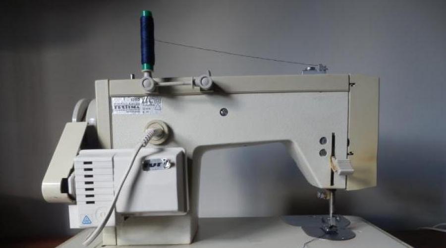
Setting up the car by a mechanic, for himself.
Photo 1.
Inspection of the machine by a mechanic. Identified, preliminary, violations:
- Hole in the needle plate, beaten with needles.
- Tight move, perhaps only - no lubrication.
- In the upper thread tension regulator, they do not work: neither the compensation spring, nor the plates, when lifting, the foot rod.
- When the pulley rotates, the machine goes astray, on its own, to wind the bobbin. (Idling).
- Control knobs are tight.
- The wire coming out of the machine ends with a plug after 11.5 cm. (not a convenient voltage connection, at least a meter and a half).
- A car with a cabinet, they occupy a lot of space in the apartment.
- There is a crack in the bobbin in the shuttle - it needs to be changed.
- The shuttle is worn out. Change!
On photo 2, we make such a table. - Top view of the car
- 60 mm front.
- Rear 117 - 120 mm,
- Machine width 178 mm.
- Plywood thickness 10 mm.
Photo 2.

On the photo 3, Let's make this table. Top view of the car
- Length 234 mm - from the front.
- Machine length - 373 mm.
- From the side of the pulley - 230 - 290 mm. For reel seat, for industrial reels.
The hole is rectangular, it was vypyalyan earlier. The sheet of plywood was intended, originally, for other purposes.
Photo 3.

On the photo 4, the height of the screwed box is 80 mm.
Everything, the portable table is ready, it remains to clean it with sandpaper, across the fibers, wood and open it with varnish.
Photo 4.

On the photo 4-1 a stand is shown for picking up thread from bobbins.
Photo 4-1.

Now let's take care of the car
On the photo 5, on the large clutch screw, a small screw, unscrewed it 2.5 turns.
Photo 5.

On the photo 6, on the left is the clutch screw, on the right is a washer or ring with external ears and internal antennae.
- Removed flywheel.
- Seat, flywheel cleaned on:
- main shaft
- Inside the flywheel, sandpaper.
When installing the flywheel, in place, the cleaned places were lubricated with oil, and when installing the ring with ears, the antennae should look out. This ring has two positions. But only one of them is correct. That's right - this is when the clutch screw is tightened, and the small screw is caught between the ears.
Photo 6.

On the photo 7, Needle plate and two screws.
- Screw head diameter 7.4 mm.
- Head thickness - 2.8 mm. Above, the convex part is 0.3 mm, it has a slot.
- The total length of the screw is 9.8 mm.
- Thread length - 6.5 mm.
- Thread pitch 0.7.
- Transition from a carving to a head - 1 mm. With a decrease in diameter, by 0.5 mm.
Photo 7.

On the photo 8, a strip of velvet, emery cloth is inserted into the hole of the needle plate.
We press with the fingers, of the left hand, to the edge being turned, and with the right we pull at one end of the emery cloth, then at the other. Within a minute. So removing chamfers - sharp edges, we prevent breaks in the upper thread in the needle plate. First cut on one side, then on the other.
Photo 8.

On the photo 9, dimensions are given for the manufacture of the adapter. Diameter 10.7 accurate.
Photo 9.

On the photo 10, the same adapter, view upside down.
- The largest diameter, you can set 11.
- But the calculation, lead from 10.7.
- In section 15, from below, up to the axis of the screw 7.2 mm.
- And the depth of the groove, with a size of 4.3, is 7.2 in depth.
- And from the outer surface, in section 4.3 washed down, 11.2 mm long, from top to bottom and 7.2 mm wide, along the cut - 4.3.
Photo 10.

On the photo 11, Screw with spaced sizes. This is one screw, out of two identical ones, installed on the adapter.
Photo 11.

On the photo 12, unscrewed two screws, and removed the conveyor block. And also with the tip of a screwdriver, its grooves are cleaned of many years of accumulated dirt.
Photo 12.

On the photo 13, photo of two screws with dimensions for manufacturing, by a turner, in case of loss.
Photo 13.

On the photo 14, check with the tip of the nail, the rib along which the upper thread slides, leaving the hook. On needle strikes, unevenness and roughness, all this will need to be removed. Otherwise, breaking the upper thread cannot be avoided.
Photo 14.

On the photo 15, no gap is shown between the bobbin and the adjusting pin.
Thin lines, I indicated the approximate size of the gap. It is in the range of 0.5 - 1 mm. And also you can see the absence of one of the screws, with a clamping, restrictive cover. Holding the bobbin, on the guide track, the shuttle. It needs to be rotated.
Photo 15.

On the photo 16, top screw, dowel pin fastening.
Unscrew the screw and remove the mounting pin.
Photo 16.

On the photo 17, sketch for turner, screw, setting pin.
Photo 17.

On the photo 18, The setting finger, with red lines, indicated the edges to be chamfered, they contribute to the breakage of the upper thread, when the thread is pulled out, by the thread take-up from the hook.
Photo 18.

On the photo 19 - Edges, more close.
Photo 19.

On the photo 20, the edge facing the shuttle is visible burr, subject to destruction by sawing.
Photo 20.

On the photo 21, remove the casing to check the integrity of the teeth on the gears. On the cover, there are three screws. One is the same as photo 17.
Photo 21.

On the photo 22, one of two identical screws from the casing fastening.
Photo 22.

On the photo 23, rotating the pulley, we check the presence of teeth on the gears.
On the shaft, shuttle, machine Veritas Avtomatik, kapron gear. And the bottom, metal, diameter is 26.5 mm. 22 teeth. Shaft diameter 7.5 mm.
Photo 23.

On the photo 24, loosening the screws on the seat of the shuttle, and removed the shuttle. up.
Photo 24.

On the photo 25, shuttles from industrial machines.
- Shuttle 22 class. Seat diameter 7.2 mm.
- Shuttle 1022, the first production of machines. The hook is soldered, privately, to the bobbin case. The hook and bobbin case are dismantled. seat diameter 7.7 mm
- Shuttle 1022, subsequent editions. Seat diameter 7.7 mm
- Shuttle 1022 M class. A hole in the bobbin case, under the spring, it is inside the cap. Seat diameter 8.2 mm
According to the seat, the shuttle of the 22nd class is most suitable for us. Since the diameter of the shuttle shaft, 7.2 mm.
Photo 25.

Shuttle device.
On the photo 26, a shuttle is shown, it consists of:
- Spring screw, bobbin case.
- Second screw, bobbin case springs.
- Spring. bobbin case.
- Latch, bobbin case.
- Landing axle, bobbin case, in the bobbin case.
- Seat, in the bobbin, for the adjusting pin.
- Belt, under the bobbin.
- technological openings.
- Screw, thread protector.
- Thread protector. I call the dovetail plate.
- Seat, bobbin belt.
- Seat, thread protector.
- Screws, there are 3 of them, fastening the shuttle, to the shuttle shaft.
- Screws, there are 3 of them, fixing the patch plate.
- Overlay plate.
- Large, technological hole in the shuttle.
- Shuttle nose.
- Thread gripping slot in the bobbin band.
- Mounting pin. Photo 18.
- Mounting screw, mounting pin, to the machine body.
- Plate, body, mounting pin.
- Half hole, for fixing, latch, bobbin case.
- Bobbin thread guide.
- Bobbin. Spool.
- Pin axis, bobbin case latches.
- Cam, latches.
- Cover plate, bobbin case.
- Locking screw, patch plate. Designed to limit travel, overlay plate.
- Lock, patch plate.
- Tongue, patch plate.
- The handle is a latch.
- The spring against which the tongue abuts, the patch plate.
- Slot under the lock, in the bobbin case.
- The seat of the spring, in the bobbin case.
- Restrictive opening, under a cam, handles-latches.
Photo 26.

On the photo 27, spout of a new shuttle, from an industrial machine of the 22nd class.
Photo 27.

On the Photo 28, Techstim's shuttle.
Pay attention to the length of the groove, inlet, needle. Machine class 22 straight stitch, and Veritas Avtomatik, a machine with a zigzag. So, in the class 22 shuttle, I installed a bobbin, from the Techstim machine.
Photo 28.

On the photo 28-1, inlet in the bobbin, Tekhstim machines.
Photo 28-1.

On the photo 29, shows the entrance of the needle, on a straight line:
- Dressed for a seat, a shuttle.
- Turned the nose of the shuttle to the lowest position.
- So that the bobbin does not interfere with the exhibition of the shuttle, it is installed - an adjusting pin. Without exposing or tightening the screw. To abut the bobbin.
- In this position, holding the shuttle, from turning, the screws are not twisted, rotating the pulley, lowered the needle to the lowest point. "Lower zero".
- And only here, I discovered that a needle with a short flat, for a straight-seam machine. See article Needle! I had to change the needle.
- I put the needle with the needle bar, relatively under the bobbin. Look at photo 2, the bottom of the needle hole, flush with the bottom edge for the bobbin. It will be lower, the needles will break, on the edge of the bobbin!
- Here in this position, slightly, I twist the screws, fixing the shuttle, on the seat.
Photo 29.

On the photo 30, Left needle prick, side view, needle flats. Zigzag 4 mm.
If you look from the back of the machine at the seamstress sitting behind the machine, then the injection is right.
- We rotate the pulley to the intersection of the nose of the shuttle with the flat of the needle. The needle has risen to the intersection with the nose of the shuttle.
- We set the gap between the nose of the shuttle and the short flat of the needle.
If only thin fabrics will be sewn on the machine, with needles from No. 60 - 100, then needle No. 100 is put on the installation. When sewing with thicker needles, a maximum of No. 120 is set.
The gap between the plane of the nose of the shuttle and the plane of the flat of the needle is 0.1 - 0.15 mm.
Needle No. = Diameter (needle shaft) x 100!
Photo 30.

On the photo 31, The left prick of the needle - at the intersection - with the nose of the shuttle - along the flat of the needle.
Photo 31.

On the photo 32, after I have set the shuttle, relative to the needle, I set the gap between under the bobbin and the setting finger. Throat depth, half.
So that under the spool, it does not turn. And so that the thread, in 6 additions, passes freely.
Photo 32.

Everything can be put in place: the conveyor block and the needle plate.
We check the shafts, from the bottom of the machine, for axial play:
We take the shaft with our fingers and along its length - we pull to the right - and to the left.
Shaft play should be within 0.1 - 0.15 mm. If somewhere more, then it is set with the help of a restrictive distance sleeve.
(The shift should not be visible to the eye, but there is a shift to the touch!) - this is 0.1 mm
Loosen the screws on the bushing, move the shaft, press the bushing, tighten the screws.
On the photo 33, shows the bottom of the car.
Here are the part names:
- A shaft that transmits movement up and down the conveyor block.
- A bracket that transmits the movement of the conveyor block to the movement of material.
- The shaft that transmits the movement to the bracket No. 2, to move the material, with a conveyor block.
- The shaft that transmits the movement to the shuttle shaft.
- Clamp pull. Transmitting movement to the shuttle shaft.
- Fork pull. Transmitting movement, for lifting and lowering - to the conveyor block.
- Screw for adjustment - exhibition, conveyor block in the middle of the grooves - needle plate. To perform the binding.
- The screw, for setting the gap, the adjusting pin, relative to the groove - in the bobbin.
- Screw, for exhibition. The height of the teeth, the conveyor block - in height.
Adjustments, conveyor blocks.
Adjustment, conveyor block, is made relative to the top - needle plate.
Setting one:
The procedure for the exhibition, the conveyor block to promote the material.
- With the needle plate in place, place the machine on the back of the arm.
- Stitch length dial, set to zero.
- With the flywheel, raise the needle bar - up. The conveyor block will also accept - the upper position. If not. Then you lost the eccentric on the main shaft. Expose it first.
- By photo 33, loosen the screw № 7, on the bracket. He's screwed.
- Turn around the axis, the shaft - the bracket that transmits the movement - to the conveyor block, to advance the material. So that the conveyor block stands in the middle of the grooves - the needle plate.
- In this position screw number 7, on the bracket, clamp!
Second setting:
The procedure for the exhibition, conveyor block, height:
- With the needle plate in place, place the machine on the back of the sleeve as photo 33.
- With the handwheel, lift the needle bar up. At the same time, the conveyor block will stand in the middle of the grooves - the needle plate. Maximum - top position. In this position:
- Loosen the screws on the bracket. No. 10 and No. 8.
- Clicking on the bracket , with screw number 10. The top of the teeth, the conveyor block, will rise up to its maximum height.
- But for sewing thin fabrics, the top of the teeth should rise, above the needle plate, no more 0.8 - 1.2 mm.
- For sewing rough materials 1.2 -1.5 mm.
- Leather 1.5 - 1.8 mm.
- Set the height of the teeth you need, under the material that you will sew.
- In such a position screw on bracket no. 4, tighten!
The adjustment is made when switching the switch, the height of the conveyor block, which is in the off state. The handle is on the platform, from the top. See photo 1.
After setup:
- loosening screw no. 10,
- insert a finger into the silver bracket. So that it enters the fork of bracket No. 2.
- Tighten screw no. 10.
Photo 33.

On the photo 34, front part shown, machines:
- Front cover.
- Safety shield, bulbs.
- Cartridge wire.
- Mounting screw, protective cover.
- Pressure spring.
- Adjusting screw.
- Rod - paws.
- Lift lever, presser foot bar.
- Axis, lift lever, presser foot bar.
- Needle bar frame.
- Screw access hole, height adjustment of the needle bar.
If your needle hole is higher than in photos 30 and 31, then you need to loosen the screw, lower the needle bar, with the needle, down! Tighten the screw again!
A height failure occurs if the needle hits, when sewing, a solid object:
- Button.
- Snake castle.
- Axis, pressure lever, pusher rod, tension regulator, upper thread.
- Push lever.
- Rod - pusher.
- The top plug of a core - a needle bar.
Photo 34.

On the photo 35, the screw is shown, fastening the upper thread regulator to the machine body.
We unscrew it counterclock-wise, 3-4 turns. And take out the controller.
Photo 35.

On the photo 36, regulator removed from the machine.
Photo 36.

On the photo 37, parts list, from left to right:
I unscrewed the nut, it is on the right, loosened the screw on the base by 1-3 half turns. And everything lies, unfolded.
- Base.
- Inserted into the base is the axial rod.
- On the rod, compensating spring.
- Inside, a rod is inserted - a pusher. One edge, with a plus. L -27 mm. Diameter 1.8 - 2 mm.
The pusher rod, inside the axial rod, should move easily, without jamming.
- The axial rod is inserted into the base.
In the place where a slot is made on the base, under the compensation spring. And then it turns, at such an angle that the bottom of the compensation spring does not reach, to the right stop - 0.5 mm. Here in this position, he clamped the screw on the base.
- Now on the axis, I put on a small washer No. 5.
A small washer prevents the spring coil from popping out of the base. It is desirable in the manufacture of the base, to make the inner diameter not 10.5 but 11.5 mm. So that the compensation spring was not so crowded.
- Now, we put on the first plate, on the axial rod No. 6.
- Separating washer, in order to be able to sew on the machine - with two threads No. 7.
- The second plate, curved part, to the separation washer No. 8.
- Washer with bridge No. 9. Curved bridge, to the side, pressure nuts. Very often, it is installed, back to front.
- Now large washer No. 10. Rectangular slot, at the top.
In photo 37, the part that is shown at the top is placed on the axial rod, facing the curved part, of the washer with a jumper.
- Spring wide end, to the cylindrical washer, bent end of the spring, into the slot, the axial rod. turn the nut.
On the photo 37,washer number 10- lies upside down.
Photo 37.

On the photo 38, axial rod - "axle".
This is a sketch for a turner. Axial rod - "axle" sometimes breaks. After turning on a lathe, heat treatment is necessary, since thread - abrasive and very quickly - it will grind the axle!
Photo 38.

On the photo 39, sketch for a turner. This is the foundation. The part that is inserted into the body of the machine.
Photo 39.

On the photo 40, when the foot is lowered, the pusher rod, to open the plates, presses on the washer, with a curved bridge - in the middle.
Photo 40.

On the photo 41, presser foot raised above the needle plate.
The bracket - the handles for lifting the rod-foot, pressed the pusher - into the washer with the jumper, from this the plates - unclenched. And now, the thread is not clamped by plates. That is, it moves freely.
Common seamstress mistake: Adjusting the tension of the upper thread - do it with the raised foot! And they say - "Thread, not regulated!"
Photo 41.

Exhibition of the presser foot shank, for all classes of machines.
Malfunctions encountered when setting up machines are shown in photos 11 and 12. And a method for eliminating them is described, in four stages.
Fault: The presser foot is not set correctly, in height:
On the photo 42, the foot is raised up. The needle bar goes down and rests on the foot.
Here is a list of the front parts:
- Pressure screw.
- The body is a nut, (it) is screwed in, a pressure screw.
- Spring.
- Bracket with screw 5.
- Screw - for adjusting the stem of the foot, in height.
- Leg stem.
- Foot.
- The rod is a needle bar.
- Bracket with a screw, on the rod - a needle bar.
- Needle plate.
Elimination:
First stage:
On photo 42, No. 4 - on a bracket with a ledge, which rests on the paw holder No. 6. Lower screw number 5, for 1 - 2 half a turn. At the same time, the bar of the presser foot holder should go down. If this didn't happen:
- It is necessary, on the stem of the paw holder in the area of \u200b\u200bthe number No. 7, to drip 2 drops of oil I 18 or I 20 A (spindle).
- Turning around the axis, the bar of the foot, within the lowered needle, ensure that the bar of the foot drops. If it doesn't rotate then:
- Take a rod with a diameter of 5 - 6 mm, a length of at least 50 mm photo 43.
- Lower into the hole, pressure screw No. 1.
- Tap lightly with a hammer. After that, the presser foot bar will go down immediately. Provided that the screw number 5, on the bracket number 4, is loose.
Photo 42.

On the photo 43, the foot is down. But in height, it does not reach, up to the needle plate.
- Pressure screw.
- The housing is screwed into it, a pressure screw.
- Spring.
- Bracket with screw 5.
- Screw - for adjusting the stem of the foot in height.
- Lever - lifting the bar of the foot.
- Leg stem.
- The lower part of the body. Sometimes in it, there is a lower sleeve.
- Foot.
- Needle bar.
- Bracket with a screw, on the needle bar.
- Needle plate.
- Conveyor block.
Second phase. Photos 43 and 44:
- Through pressure screw No. 1, (where the rod was inserted) we drip 1-2 drops of oil - I 18 A or I 20 A
- We lower to the bottom - Lifting handle No. 6, foot holder bar No. 7.
- So, the foot lay down, on the needle plate, with the entire lower plane. Photo 44.
- We turn the foot, relative to the needle, so that between the flat of the needle, (left) to the inside of the foot, the distance is two to three times greater than between the long slot and the inner edge of the foot (right). Well, so that by eye, she fed the material evenly, relative to the grooves - the conveyor block.
Photo 43.

Third Stage. Photo 44.
Sometimes it happens, on a very dirty car, that bracket No. 4 hangs in the air, with the foot lowered.
Elimination:
- Screw number 5, loosened.
- With the same pin, on which they beat, we set on the top of bracket No. 4. And lightly hit with a hammer.
- From this action, bracket No. 4 will lower onto bracket No. 6, cleaning the foot shaft from dirt.
- On this cleaned place, drip 1-2 drops of oil.
- We raise the lifting handle, No. 6, by 2 - 3 mm. At the same time, bracket No. 4 will also rise by this amount.
- Holding the lifting handle, No. 6, in this position, tighten the screw No. 5, on the bracket No. 4.
The fourth stage, usually the only one, on a clean machine:
On machines, only with a straight line.
- Needle bar.
- Needle holder.
- Foot.
- Needle.
- Needle plate.
- Conveyor block.
General setting, Front:
Restoration of working capacity, pressure screw springs.
We make the setting by photos 43 and 44.
- We unscrew the screw by pressing on the spring photo 12#1, completely.
Under the screw, there is usually a washer!
- Spring No. 3, with a washer, pull it up, stretch it by 1/3 of its length.
- We put the spring back on the rod - paws, put on the washer and tighten screw No. 1, completely.
- We unscrew the screw, half the thread. By returning this operation, the stiffness of the spring.
- The stem of the foot, with the lifting handle No. 6, is lowered down. The sole of the presser foot should rest on the surface of the needle plate. To do this, turning the flywheel towards you, the conveyor block (top of the teeth) should fall below the needle plate.
- In this position, loosen the screw number 5 on the bracket number 4.
- By turning the stem of the foot, around the axis, we expose the foot, relative to the needle. 2/3 of the free part of the slit of the foot should be on the side of the flat of the needle.
- Raise, with lever No. 6, by 2-3 mm, bracket No. 4. Tighten screw No. 5.
On the photo 44, foot position relative to the needle.
Photo 44.

On the photo 45, stitch length regulator. I set it to (0) zero.
Photo 45.

On the photo 46, top cover removed.
Pay no attention to the numbers in this photo!
Photo 46.

On the photo 47, screw on axle bracket, stitch length dial. In position (0), it is in a horizontal position. From the bracket to the top - there is a metal rod.
When the screw is tightened, under it is a spring, the handle is fixed in one position. And until you unscrew the screw, you will not move the handle from its place.
Photo 47

On the photo 48, the rod is connected to the bracket, into the axis of which the brake screw is screwed.
Photo 48.

On photo 49:
- stitch length knob brake screw.
- the body of the machine, an axle passes inside it.
- bracket in the form of a channel, a rod is attached to it.
- A square cracker is inserted into the channel - it is brass, dark orange.
- It is dressed on an axle mounted horizontally, on a rod, with a fork.
When screw No. 1 is tightened, the stitch length knob will switch with force. And when sewing, will not move.
Photo 49.

On the photo 50, pictured zigzag width knob.
In this photo - set in position (0) - straight stitch.
Photo 50.

On the photo 51, needle position knob relative to the needle plate.
(Now the handle is set to L-1.)
Photo 51.

On the photo 52, The needle is on the left, relative to the center, of the needle plate.
Photo 52

On the photo 53, handle in position M - 2.
Photo 53.

On the photo 54, The needle matches, the axis of the hole, in the needle plate.
Photo 54.

On the photo 55, handle in position R - 3.
Photo 55.

On the photo 56, the needle goes down and up, in the extreme, right position.
Photo 56.

In photo 57, - "Needle switch knob", in position M - 4.

On the photo 58, in positions M - 2 and R - 4, the needle is again, in the middle of the needle hole.
Photo 58.

Consider now the needle mixing mechanism.
On the photo 61, unscrewed screw number 2. And pulled the zigzag handle out of the machine body. Here is the seat.
On the photo 59, the seat of the zigzag width knob is shown.
Photo 59.

On the photo 60,zigzag width knob.
On the axis of the handle, washer, slotted. A screw is screwed into the plastic part of the handle. Between the screw and the plastic handle, a spring. Its purpose is unclear. The handle is inserted into the seat, with a tooth. This tooth is the handle rotation limiter. The washer is not hardened, and has no rigidity. Screw with spring - designed to fix the handle in the position of the zigzag width of 1 mm and 3 mm. With the screw turned out, the handle spontaneously sets to position (0) ; (2) ; (four).
Pretty bad design. It would be better if, instead of this washer, recesses-holes would be drilled in the seat. Through each mm, along the arc, the handle pointer. And in the seat of the screw, there would be a ball and a spring, as well as a pressure screw - compressing this spring. Then the fixation of the handle will be rigid, in all positions. And light, when switching.
Photo 60.

In photo 61, the assembly is shown, near the flywheel, under the top cover of the machine:
- A fork that transmits movement to transport material.
- Eccentric bushing.
- main shaft.
Photo 61.

On the photo 62 shows the engagement of the spring, from the bottom of the platform:
- Shown is the spring mounting on the bottom of the machine.
- Screw for fastening the platform to the sleeve.
- Upper transmission shaft. See photo 33. Near the number number 8
- Bracket of fastening of draft with a fork.
Photo 62.

On the photo 63, the same as on photo 61, view from the side of the pulley.
- Vertical traction fork.
- Eccentric bushing.
- Mounting screw on the bracket into which the zigzag handle is inserted.
- Retaining ring, on the axis of point 1.
- Spring, top mount.
- Screw for fixing the axle on which it is installed
- Control lever for the first block of copiers.
- Place of attachment of the vertical rod.
- main shaft.
Photo 63.

On the photo 64, Back view:
- Vertical traction fork.
- Eccentric bushing.
- Mounting screw on the bracket into which the zigzag handle is inserted.
- Retaining ring, on the axis of point 1.
- Belt drive - belt.
- Screw for fastening the axis on which the control lever of the first block of copiers is installed.
- Control lever for the first block of copiers.
- Place of attachment of the vertical rod.
- main shaft.
Photo 64.

On the photo 65, view from the front, the needle offset handle, relative to the hole, the needle plate - to the right.
This article was written first, After it, an article was written with the same zizag block. If in this article, something is not clear to you, you can read about it more briefly by clicking on this link: Veritas 8016/33
- Plastic four-sided cam.
- Plate spring.
Photo 65.

On the photo 66:- View from the side of the pulley.
- Bracket - copier mounted on axis No. 1 of the zigzag block.
- Plastic, eccentric, three-sided, cam. When the handle is rotated, the displacement of the needle relative to the hole, the needle plate, rotates with the axis. Behind pinned with a tubular pin.
- Axis, handles, needle offset relative to the hole, needle plate.
- Curved bracket, first, upper block, with copiers.
- The screw, on this rod 5, in photo 56, regulates the position of the needle, relative to the edges and in the center, of the needle hole.
- The gear is called a worm.
- Worm gear.
- Plastic copy wheel, second block, top zigzag.

Consider the zigzag mechanism, from above, photo 67.
- Fork pull.
- Thrust.
- Belt.
- Rusk.
- A rod that transmits displacement to the needle bar frame.
- Bracket mounted on the axis of the first worm gear.
- Curved bracket connecting the channel frame with the first block of copiers
- Place of fastening, thrust transmitting displacement, needle bar frame.
Photo 67.

Pulley side view. Let's see how it works.
On the photo 68, When the flywheel - pulley rotates, the main shaft 1 begins to rotate. A gear - a worm is installed on the shaft. Above it, worm gear 2. This worm gear is mounted on a fixed axle. Under the number 2, on photo 68, locking screw of this axis. At the other end of this axis, there is a cam, 3. This cam, striking from the right, then from the left, causing the brown bracket in the form of a channel, swings like a pendulum. The screw is inserted into the rod 7, transmits, the displacement of the frame, the needle bar. Then roller 6 is put on it. And the nut is crouton 4. When crouton 4 is in the upper position, no movements are transmitted to thrust 7, the machine sews, a straight line.
Photo 68.

View from the front side. On the photo 69, when we shift, the zigzag width knob, from zero, the rod 5 lowers the cover with cracker 1, sliding on the bracket in the form of a channel 2. (This bracket, mounted on a rotary axis, in a silver bracket mounted on a fixed axis). Bracket 3, swinging from side to side, also swings cracker 1. The lower the cracker goes down, the more the screw axis screwed into the cracker deflects. From this, the transmission of movement occurs, through traction, displacement, needle bar frames. On the photo 58 on the roller 6, the fork is put on, the bracket 8. This bracket 8 is connected to the first zigzag block.
Photo 69.

On the photo 70, view from the front.
- Thrust.
- Rusk.
- Cam.
- Bracket channel.
- A rod that transmits displacement to the needle bar frame.
- Bracket with fork.
Photo 70.

On the photo 71, only in position L - 1 unit No. 2 is switched on.
- Rusk.
- Screw.
- On the screw, a rod that transmits displacement to the needle bar frame.
- Bracket with fork.
Photo 71

On the photo 72, figures show plastic single-turn, worms. They are not movable in a horizontal plane, but rotate with the worm wheel.
- Zigzag block No. 1.- Reading copier.
- Zigzag block No. 2 - Reading copier.
Photo 72.

On the photo 73, numbers and English letters, "wheels" - "stars" - "gears" are attached to them - horizontal drums. Rotating, a single-turn, worm wheel, with the upper coil located on it, millimeter by millimeter, moves along the tooth of the upper drum. photo 74, From this, the drum, fixed in the bracket, either rises to the top or falls to the bottom, transferring these movements to the thrust that transmits the displacement, the frame, the needle bar. photo 71, through a bracket with a plug, 4.
Each tooth on the top reels is a Copy Disc! And the worms under these drums are copiers
Photo 73.

When the device is understood, it becomes much easier to fix the problem that has appeared. Disassemble and troubleshoot!
Let's move on to adjusting the thread tension:
First of all, choose the bobbins
In photo 74, the bobbin is inserted into the cap. There is a needle plate on top.
Bobbin in height, matches the edges of the bobbin case.
Photo 74.

On the photo 75, it is shown how to correctly install the bobbin into the cap.
Here's what you need to pay attention to:
- Groove, in the bobbin, for the thread to enter the cap. Should not have sharp edges!
- Cap spring. Should not have chafing, on the inside!
- The adjusting screw, when twisting, clamps the thread more strongly. At the spring, when the screw is unscrewed, the pressure weakens.
Twist, clockwise, unscrew counter-clockwise! And there should not be, on a screw, sharp slots and burrs on them! We cut with a file.
- Seat, bobbins. In it, there should be no dust and lint!
- Bobbin. Must match the size of the bobbin case!
- A thread.
Photo 75.

On the photo 76, shows how to adjust, spring screw, on the cap:
- Let's take the thread.
- We take the thread, the cap with the bobbin hangs. Photo 33. The thread is not pulled out. If it pulls out, tighten the screw, 1 - 2 turns.
The bobbin case, with the bobbin correctly installed, should hang on this thread!
- Little - We twist the screw, on the bobbin case, another 0.5 turns, clockwise.
- We take the thread, for testing. Few?
- Another 0.5 turn, twist and try.
- Everything is hanging!
- Now, lightly shake the bobbin case.
Photo 77. Threads should move from 5 - 15 cm, depending on the shaking strength. But the bobbin case should hang in the air again. And the thread from it should not spontaneously unwind!
Photo 76.

On photo 77, bobbin case, after shaking.
Photo 77.

Let's move on to adjusting the upper thread:
The guideline for adjustment is the thread tension in the line!
When changing the thickness of the thread, between the plates, tighten the nut, if the thread is thinner, unscrew it. If the thread is too tight, it will break.
If the thread is thicker, unscrew it.
So, having made a mark on the nut - with a felt-tip pen, you need to tighten it for 15 minutes, a little more for 15 minutes, a lot - loosen it for 7.5 minutes. Then - 3.25, etc.
If knots are visible at the top, in the line, this is a strong upper thread. If you lift the material, then we will see the lower thread. If it is free and not pulled into the punctures of the needle, this means that the upper thread is weakly clamped in the plates.
Example Photo 78:
The bobbin thread is not taut in the bobbin case!
This photo indicates that the upper thread must be loosened! That is, unscrew the nut for 15 minutes. Flash! Few? For another 15 minutes. Until a line appears, as in photo 80.
Photo 78.

On the photo 79, upper thread, in plates, very loose!
You need to tighten the upper thread. To do this, tighten the nut for 7.5 minutes! Few? Another 3.2 minutes. Until a line appears, as in photo 80.
Photo 79.

On the photo 80, thread tension adjusted correctly!
But in order to see such a line, it is necessary to tear off the threads from the stitched piece of fabric. And try to slightly separate the top fabric from the bottom, as in photo 81.
Photo 80.

On the photo 81, thread tension adjusted correctly!
The interlacing of threads - occurs strictly - along the axis of the materials being sewn.