12 volt temperature regulators. How to assemble a thermostat at home. DIY electronic thermostat, device diagram
Read also
The universal digital thermostat TR-12V-DS is designed to measure and maintain temperature within specified limits (from -55 to +125°C), and can be widely used for precise temperature control in electrical circuits with a voltage of 12 Volts.
Application area
The temperature regulator TR-12V-DS is most in demand for use in automotive vehicles with a 12V on-board network; can be used in incubators, brooders; V various systems battery-based solar panels and others alternative sources energy; in equipment powered by 12 Volts. The temperature sensor is the widely used high-precision digital sensor DS18B20.
Functionality
The climate control thermostat TR-12V-DS measures the temperature value at the location of the sensor and gives a command to turn the load on or off via an electromagnetic relay. Any heating or cooling electrical appliances can be connected to it. Wherein, maximum power connected devices should not exceed 2500 watts active load(10 Amps at cos? = 1).
The device has settings for the temperature that must be maintained and hysteresis, that is, the temperature difference between turning on and off the load, thanks to which you can set a wider temperature “corridor” and avoid excessively frequent operation of the relay. The universal thermostat TR-12V-DS can be configured for both heating mode (turning on the heating device when the temperature drops below the set one) and cooling mode (turning on the cooling device when the temperature rises above the set one). In addition, the thermostat has a built-in timer, thanks to which you can program the thermostat to maintain the temperature for a certain time (maintain the temperature for X minutes -> turn off until manually turned on) or to operate in a cyclic mode (maintain the temperature for X minutes -> idle Y minutes -> maintaining temperature...). The device also has the ability to limit the specified upper and lower limit range of maintained temperatures.
The thermostat comes in a small transparent case 6 (8) x 5 x 3 cm and has holes for fastening with self-tapping screws (screws) on any suitable surface.
|
Parameter |
Meaning |
|
Temperature range |
from -55 to +125 °С |
|
Resolution |
0.1 °C, 0.1 °C in the range from -9.9 to +99.9 °C, 1 °C in the range from -55 to -10 °C and from +100 to +125 °C |
|
Temperature measurement error |
|
|
Hysteresis (difference between switch-on and switch-off temperatures) |
plus or minus from 0 to 50.0 °C |
|
Run timer time |
from 0 to 999 minutes |
|
Idle Timer Time |
from 0 to 999 minutes |
|
Sound signaling of the end of the process |
|
|
Selection of operating logic |
heating or cooling |
|
Maximum switching current at cos? =1 |
|
|
Sensor connecting wire length |
|
|
Device supply voltage |
12 Volt AC/DC |
|
Installation (connection) method |
on a flat surface, portable case |
|
dimensions |
6 (8) x 5 x 3 cm |
In this article we will consider devices that support a certain thermal regime, or signal the achievement of desired value temperature. Such devices have very wide scope applications: they can maintain a given temperature in incubators and aquariums, warm floors and even be part smart home. For you, we have provided instructions on how to make a thermostat with your own hands and at a minimum cost.
A little theory
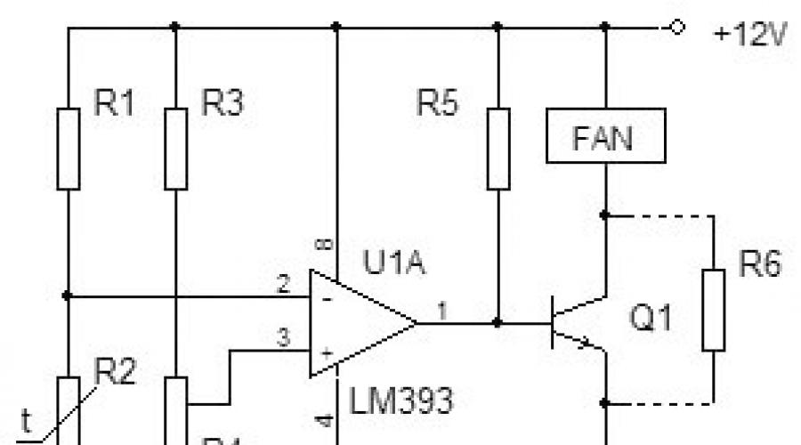
The simplest measuring sensors, including those that respond to temperature, consist of a measuring half-arm of two resistances, a reference and an element that changes its resistance depending on the temperature adjusted to it. This is shown more clearly in the picture below.
As can be seen from the diagram, resistor R2 is the measuring element of a homemade thermostat, and R1, R3 and R4 are the reference arm of the device. This is a thermistor. It is a conductor device that changes its resistance with temperature changes.

The thermostat element that responds to changes in the state of the measuring arm is an integrated amplifier in comparator mode. This mode abruptly switches the output of the microcircuit from the off state to working position. Thus, at the output of the comparator we have only two values “on” and “off”. The load of the chip is a PC fan. When the temperature reaches a certain value, a voltage shift occurs in the arms of R1 and R2, the input of the microcircuit compares the value on pins 2 and 3 and the comparator switches. The fan cools the required object, its temperature drops, the resistance of the resistor changes and the comparator turns off the fan. In this way, the temperature is maintained at a given level and the operation of the fan is controlled.
Overview of circuits
The difference voltage from the measuring arm is supplied to a paired transistor with large coefficient amplification, and an electromagnetic relay acts as a comparator. When the coil reaches a voltage sufficient to retract the core, it is triggered and connected through its contacts of actuators. When the set temperature is reached, the signal on the transistors decreases, the voltage on the relay coil synchronously drops, and at some point the contacts are disconnected and the payload is turned off.

A feature of this type of relay is the presence of a difference of several degrees between turning on and off a homemade thermostat, due to the presence of an electromechanical relay in the circuit. Thus, the temperature will always fluctuate a few degrees around the desired value. The assembly option provided below is practically free of hysteresis.
Fundamental electronic circuit analog thermostat for incubator:

This scheme was very popular for repetition in 2000, but even now it has not lost its relevance and copes with the function assigned to it. If you have access to old parts, you can assemble a thermostat with your own hands almost free of charge.
The heart of the homemade product is the K140UD7 or K140UD8 integrated amplifier. IN in this case it is connected with positive feedback and is a comparator. The temperature-sensitive element R5 is a resistor of type MMT-4 with negative TKE, which means that when heated its resistance decreases.
The remote sensor is connected via a shielded wire. To reduce and false alarm devices, the wire length should not exceed 1 meter. The load is controlled through thyristor VS1 and the maximum permissible power of the connected heater depends on its rating. In this case, a 150 Watt electronic switch - a thyristor - must be installed on a small radiator to remove heat. The table below shows the ratings of radio elements for assembling a thermostat at home.

The device does not have galvanic isolation from the 220 Volt network; when setting up, be careful, there is a mains voltage, which is life-threatening. After assembly, be sure to insulate all contacts and place the device in a non-conductive housing. The video below shows how to assemble a thermostat using transistors:
Homemade thermostat using transistors
Now we’ll tell you how to make a temperature controller for a heated floor. Working diagram copied from a serial sample. It will be useful for those who want to familiarize themselves and repeat, or as a sample for troubleshooting the device.
The center of the circuit is a stabilizer chip connected in an unusual way, LM431 begins to pass current when the voltage is above 2.5 Volts. This is exactly the size of this microcircuit internal source reference voltage. At a lower current value, it does not pass anything. This feature began to be used in all kinds of thermostat circuits.
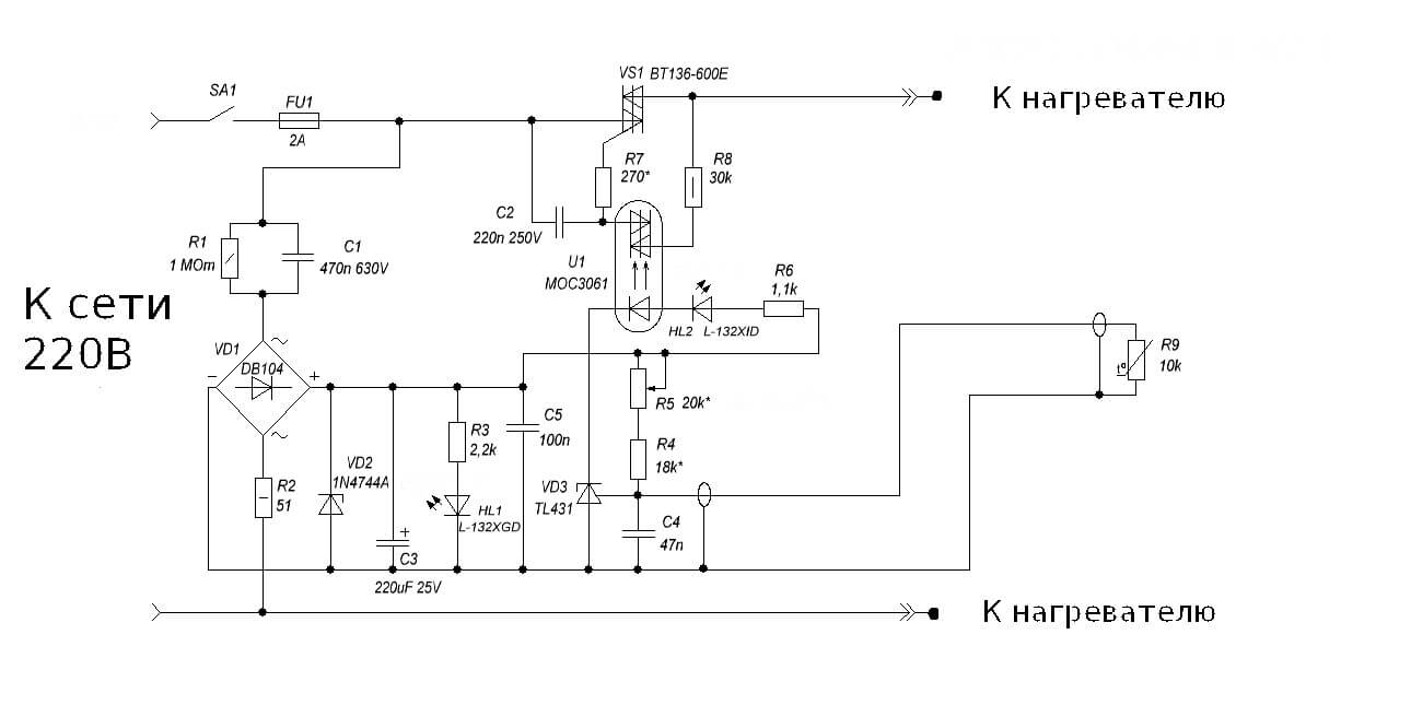
As you can see, the classic circuit with a measuring arm remains: R5, R4 are additional resistors, and R9 is a thermistor. When the temperature changes, the voltage shifts at input 1 of the microcircuit, and if it reaches the operating threshold, the voltage moves further along the circuit. In this design, the load for the TL431 microcircuit is the operation indication LED HL2 and optocoupler U1, for optical isolation of the power circuit from the control circuits.
As in previous version, the device does not have a transformer, but receives power from the quenching capacitor circuit C1, R1 and R2, so it is also under life-threatening voltage, and you need to be extremely careful when working with the circuit. To stabilize the voltage and smooth out the ripples of network surges, a zener diode VD2 and a capacitor C3 are installed in the circuit. To visually indicate the presence of voltage, an HL1 LED is installed on the device. The power control element is a VT136 triac with a small harness for control via optocoupler U1.
At these ratings, the control range is within 30-50°C. Despite the apparent complexity at first glance, the design is simple to set up and easy to repeat. Visual diagram thermostat on TL431 chip, with external power supply 12 volts for use in home automation systems are presented below:

This thermostat is capable of controlling a computer fan, power relays, indicator lights, and sound alarms. To control the temperature of the soldering iron, there is interesting scheme using the same integrated circuit TL431.

To measure temperature heating element They use a bimetallic thermocouple, which can be borrowed from a remote meter in a multimeter or purchased at a specialized radio parts store. To increase the voltage from the thermocouple to the trigger level of TL431, an additional amplifier is installed on LM351. Control is carried out through an optocoupler MOC3021 and triac T1.
When connecting the thermostat to the network, the polarity must be observed; the minus of the regulator must be on neutral wire, otherwise phase voltage will appear on the soldering iron body through the thermocouple wires. This is what main drawback this diagram, because not everyone wants to constantly check that the plug is correctly connected to the socket, and if you neglect this, you can get an electric shock or damage electronic components during soldering. The range is adjusted by resistor R3. This scheme will ensure long-term operation of the soldering iron, eliminate its overheating and increase the quality of soldering due to the stability of the temperature regime.
Another idea for assembling a simple thermostat is discussed in the video:
Temperature controller on TL431 chip
A simple regulator for a soldering iron
The analyzed examples of temperature controllers are quite sufficient to meet the needs home handyman. The schemes do not contain scarce and expensive spare parts, are easily repeated and practically do not require adjustment. These homemade products can easily be adapted to regulate the temperature of water in a water heater tank, monitor the heat in an incubator or greenhouse, and upgrade an iron or soldering iron. In addition, you can restore an old refrigerator by remaking the regulator to work with negative temperature values, by replacing the resistances in the measuring arm. We hope our article was interesting, you found it useful and understood how to make a thermostat with your own hands at home! If you still have questions, feel free to ask them in the comments.
After the New Year's holidays, long-awaited packages begin to pour in. So I received a thermostat for one of my DIY gadgets (I mentioned it in my review).
A similar one was already here in who wrote
But this one, although somewhat more expensive, has more settings, and the relay is more powerful.
Seller Description:
Temperature range: -9-99 Celsius
Accuracy: 1 Celsius
Control accuracy: 1 Celsius
Setting range: -9-99 Celsius
Refresh rate: 0.5S
Input power: DC12V
Output: relay output, capacity 220V 10A/12V 10A
Environmental requirements: -10-60 Celsius
Humidity: 20%-85%
Size: 78x51 mm
Temperature sensor: NTC (3950-10K 1%)
Applicable to various spatial temperature control, water temperature control, incubators, etc.
Lights, digital tube, key state Description
Red start indicator:
Start (red) indicator which means the relays are closed, the device starts working
Green brake light:
Stop (green) light which means the relay is disconnected, the device stops working
Digital pipe
Middle red LED display for current temperature detection, left side green digital display tube as set start temperature, right side green digital display as set stop temperature.
We connect it to the ancient long-suffering AT power supply unit (at the same time loading it with a fan to cool the sensor).
The thermostat “eats” 12 volts, exactly what I need.
The relay is normally open, it is indicated that the switching current is up to 10 amperes.
In addition to the current temperature, the indicators also show response limits. I’ll call them the starting and finishing temperatures (Ksiman used in his review smart word“hysteresis”, to be honest, it’s “weak” to me)

Unfortunately, LED assemblies are quite difficult to photograph, so I will also have to describe WHAT was visible there.
We set the starting temperature to 22 degrees and firmly grasp the sensor in our hand...
(start 22, current 22, finish 23) 
The temperature rises and the relay is activated - the current temperature is 24: 
If you need to do the opposite - switching on when the temperature drops, then it is enough to make the starting one higher than the finishing one.
Starting 24, current 24, finishing 22, I cool the sensor with a fan. Cools down very slowly... 
The current consumption is quite small: 
Reverse side of the board. The relay is standard, I didn’t even load it - and you can hear the click: 
Microcircuits close-up. 

There is no sound signal when the relay is activated; the buzzer soldered on the board beeps only when the buttons are pressed.
Sensor: 
It should be noted that the set temperature thresholds are retained when the power is turned off.
That's all. Sorry for some confusion, it’s just very cold, my thoughts are confused.
The thermostat was purchased at my own expense.
I'm planning to buy +78 Add to favorites I liked the review +45 +107Thermostat for incubator Mechta-12 (12V) with control and regulation of humidity levels, as well as a programmable timer for rotating / changing the position of trays in the incubator, this is a universal electronic device that will provide high quality and reliable automatic control temperature and humidity in the incubator that you need. Provides control over the rotation of trays at specified time intervals. The device has high accuracy measurements and adjustments. Temperature - 0.1 °C. Humidity – 5%. Supply voltage 12 V.
Purpose and main characteristics
Any egg incubators require constant monitoring of temperature and humidity indicators environment. The main difficulty in this case is maintaining these parameters at constant values! After all, even 10 minutes of overheating or hypothermia of incubated eggs leads to the death of the embryo.
Humidity also plays an important role during incubation. To measure humidity, a psychrometric method is used, based on the dependence of the difference between the readings of the dry and wet thermometers of the device. This method is one of the most accurate and reliable. You can find out more about this method below.
It is also necessary to turn the eggs through certain time(minimum 3-4 turns per day) throughout the entire incubation period, this is due to the fact that the temperature difference is different sides eggs can reach 2 degrees, which leads to a decrease in the hatching of chicks.
To solve these problems, it is necessary to use various temperature and humidity control devices, and various timers. Electronic device DREAM-12 combines all these functions in one device designed and used to regulate temperature and humidity parameters, as well as to control tray turners in incubators.
DREAM-12 is a control device for instrumentation and automation. The device analyzes information coming from sensors, analyzes time intervals, and, using a relay, switches the load to external devices, serving to change climatic conditions in a controlled object, and also, if it is an incubator, then turns on the motor of the tray rotation device.
To change the temperature, any heating or cooling devices with a current consumption of no more than 16 Amps can be used - electric tubular electric heaters (TEH), incandescent light bulbs, air conditioners, refrigeration units and etc.
To regulate the humidity in the incubator, they can be connected ultrasonic humidifiers, steam generators, valves of a device that supplies water to wet hanging fabric, heated containers with water, compressors pumping air through containers with water, etc. To reduce humidity, ventilation systems can be connected to the device.
In addition to incubators, the device can also be used to measure and regulate temperature and humidity in various types premises (storages, greenhouses), in drying chambers, in living conditions, like component weather stations, etc.
Description appearance device devices
On the front panel of this model there is:
1. digital indicator showing current values temperature, humidity, service information, as well as load status (on or off)
2. control buttons (with the help of which user information is entered into the microcontroller):
M - menu; change in rank.
OK – confirmation; change in number in a place.
For adjustment and Maintenance During operation, it is possible to enter the service menu. Configurable device parameters:
- Operating time of the tray rotation timer;
- Temperature value;
- Humidity value;
- Hysteresis parameters;
- Service parameters from the service menu.
Description psychrometric method“dry-wet thermometer”: a “dry” thermometer shows the temperature of the surrounding air, and a “wet” thermometer, partially placed in distilled water, shows a lower temperature, since water evaporates from its surface due to heat consumption. Evaporation from the surface of a wet thermometer occurs more intensely, the lower the ambient air humidity. The difference in thermometer readings therefore depends on the air humidity. The lower the air humidity, the greater the evaporation rate and the greater the difference in thermometer readings. Knowing the temperature difference, you can use a special psychrometric table and find out the humidity value.
Warranty: 24 months.
The universal digital thermostat TR-12V-DS is designed to measure and maintain temperature within specified limits (from -55 to +125°C), and can be widely used for precise temperature control in electrical circuits with a voltage of 12 Volts.
Application area
The temperature regulator TR-12V-DS is most in demand for use in automotive vehicles with a 12V on-board network; can be used in incubators, brooders; in various systems based on batteries, solar panels and other alternative energy sources; in equipment powered by 12 Volts. The temperature sensor is the widely used high-precision digital sensor DS18B20.
Functionality
The climate control thermostat TR-12V-DS measures the temperature value at the location of the sensor and gives a command to turn the load on or off via an electromagnetic relay. Any heating or cooling electrical appliances can be connected to it. At the same time, the maximum power of connected devices should not exceed 2500 Watts of active load (10 Amps at cos ? = 1).
The device has settings for the temperature that must be maintained and hysteresis, that is, the temperature difference between turning on and off the load, thanks to which you can set a wider temperature “corridor” and avoid excessively frequent operation of the relay. The universal thermostat TR-12V-DS can be configured for both heating mode (turning on the heating device when the temperature drops below the set one) and cooling mode (turning on the cooling device when the temperature rises above the set one). In addition, the thermostat has a built-in timer, thanks to which you can program the thermostat to maintain the temperature for a certain time (maintain the temperature for X minutes -> turn off until manually turned on) or to operate in a cyclic mode (maintain the temperature for X minutes -> idle Y minutes -> maintaining temperature...). The device also has the ability to limit the specified upper and lower limits of the maintained temperature range.
The thermostat comes in a small transparent case 6 (8) x 5 x 3 cm and has holes for fastening with self-tapping screws (screws) on any suitable surface.
|
Parameter |
Meaning |
|
Temperature range |
from -55 to +125 °С |
|
Resolution |
0.1 °C, 0.1 °C in the range from -9.9 to +99.9 °C, 1 °C in the range from -55 to -10 °C and from +100 to +125 °C |
|
Temperature measurement error |
|
|
Hysteresis (difference between switch-on and switch-off temperatures) |
plus or minus from 0 to 50.0 °C |
|
Run timer time |
from 0 to 999 minutes |
|
Idle Timer Time |
from 0 to 999 minutes |
|
Sound signaling of the end of the process |
|
|
Selection of operating logic |
heating or cooling |
|
Maximum switching current at cos? =1 |
|
|
Sensor connecting wire length |
|
|
Device supply voltage |
12 Volt AC/DC |
|
Installation (connection) method |
on a flat surface, portable case |
|
dimensions |
6 (8) x 5 x 3 cm |