Radial fans vran. Radial fan vran Marking veza vran-du
Read also
The VRAN trademark includes fans radial type, which contain in their design wheels with backward-curved blades. As a rule, they have high efficiency, and during operation there is no discomfort from the noise of their motor. The VRAN® trademark was first registered in 2008 and since then it has been considered a model of comfort and modernity. Each fan is manufactured using the latest technical developments, and the latest equipment. All components of this product (blades, wheel discs, body walls) are cut using a laser. But the formation of parts of conical and toroidal types is carried out using controlled CNC. In this case, wheel welding is carried out using a special welding robot.
Each housing of ventilation products is made of galvanized steel using rolling technology.
Since the production of fans is carried out on high-precision equipment, serial products fully comply with the reference characteristics declared by the manufacturer. This guarantees constant high quality each fan. Trademark VRAN® manufactures its products in 16 standard sizes, providing the most wide choose device productivity, which is in the range of 300-120,000 m3/h, and the pressure indicator is about 2600 Pa.
As a rule, fans from VRAN are used in those systems where the operating technology requires high efficiency, low level noise, or the installation of several fans is provided, which will operate in parallel to each other. Such products have high technical parameters, and can also completely replace well-known series of domestically produced fans (VTs 4-70, VR 80-75, VR 86-77). It is in comparison with them that VRAN products have whole line advantages:
- There are several classes of wheel design, which depend on the size of the peripheral speed. The wheels are the basis reliable operation the fan mechanism throughout its entire lifespan. All calculations of impellers using the finite element method are fully consistent with experimental data;
- when choosing motors, the manufacturer optimized power reserves, which ultimately allows the use of designs with low installed power, which is especially important for small fans;
- provision is made for the use of fans in all rooms, which are designed according to the first design diagram. Each of them contains frequency converters, which allows you to accurately adjust the operating mode of the device during commissioning tests, as well as during further exploitation fan A method for selecting a motor according to optimal sizes, which is capable of working with a frequency converter and changing the frequency range of the current used;
- high aerodynamic performance of serial products is ensured due to the simple design of the wheel, as well as the seal that is located between the wheel and the pipe when used in the design quality technology assemblies;
- the shape of the spiral casing was slightly changed, due to which average speed air flow is reduced in the outlet section of the device, while pressure losses in the adjacent ventilation network are also reduced.
The main purpose of VRAN fans
Fans can be installed in ventilation systems standard type, as well as in the air conditioning system and air heating industrial or residential buildings. So that while moving for two hours gas-air mixtures, the temperature of which is in the range of 400-600 °C, could not harm the fan; it is manufactured using special versions of the VRAN®-DU type.
Fans come in the following types of designs:
- general industrial ones, which the manufacturer, as a rule, marks with the “H” sign;
- heat-resistant, which are marked as “F”;
- anti-corrosion (K1), which can prevent the formation of corrosion and rust;
- corrosion-heat-resistant (K1Zh) - such fans combine two types of mechanisms and their properties;
- explosion-proof (type “B” marking) - products are made according to only the first design diagram;
- heat-resistant, the mechanism of which is protected from explosions (EP) - the design is similar to the previous type of fans;
- fans that have defense mechanism from explosion and corrosion formation (VK1; VK3);
- explosion-proof, corrosion-heat-resistant (VK1Zh);
- fans are resistant to seismic activity, which can be easily combined with other types of designs listed above.
Fan mechanism from inside
In its design, each fan has Working wheel, which rotates both clockwise and counterclockwise. The wheel blades have a special shape and are curved slightly backwards. The spiral body of the device can also rotate. Fan mechanisms are manufactured according to both the first and fifth design schemes in accordance with the accepted standards of GOST 5976.
Fans made according to the first design scheme are directly connected to the engine and come in two modifications, such as VRAN6 and VRAN9. They differ in the number of blades of their impeller.
Fans that belong to the fifth design scheme contain a belt drive type in their design. Such products come in only one modification, VRAN9. In contrast, VRAN9, which belongs to the first design scheme, is equipped with motors, thanks to which it is possible to control the rotation speed.
For devices climatic version types U1, UHL1, T1 the design of the mechanism provides additional protection from atmospheric precipitation, which is equipped with the drive and exhaust part of the fan.
Fans that are used on large industrial enterprises, have a noise-insulating casing, which can significantly reduce the noise level of the device to a value of 12 dB. In this case, the overall sound pressure level decreases by 25-30 dB at a distance of 5 meters.
If desired, the customer can purchase additional components in the form of vibration isolators and flexible inserts, which allow reducing the level of dynamic loads. It will not be superfluous to acquire: flanges reverse action, frequency converters, as well as various devices, which allow you to make smooth start fan
Operating conditions
According to operational rules and regulations, in order for fans to serve their owner for many years, they must be installed outside the area where people are constantly present.
Products according to GOST 15150 standards are able to withstand a variety of climatic conditions work ranging from temperate to tropical climates.
Basic operating conditions:
The temperature around the device must correspond to:
- “-” 45 - “+” 40 degrees Celsius for a moderate climate;
- “-” 60 - “+” 40 degrees - for moderately cold climates;
- “-” 10 - “+” 50 degrees - for the tropics.
In this case, the average value of the so-called vibration velocity of all external mechanisms, which serve as a source of vibration vibrations, should be within 2 mm/s.
Dimensions and connecting dimensions VRAN fans (1st version)
| Number fan | n | n 1 | n 2 | n 3 | dimensions, mm | |||||||||||||
| A | A 1 | A 2 | B | B 1 | B 2 | D | d | d 1 | t | t 1 | Lmax | L 1 | L 2 | |||||
| Vran-2.5 | 175 | 160 | 200 | 325 | 240 | 348 | 280 | M6 | 7 | 80 | 54 | 8 | 14 | 2 | 3 | 460 | 89 | 86 |
| Vran-2.8 | 199 | 200 | 222 | 362 | 300 | 383 | 310 | M6 | 7 | 100 | 41,5 | 8 | 14 | 2 | 3 | 480 | 101 | 101 |
| Vran-3.15 | 217 | 200 | 240 | 399 | 300 | 420 | 345 | M6 | 7 | 100 | 60 | 8 | 14 | 2 | 3 | 530 | 110 | 115 |
| Vran-3.55 | 249 | 200 | 272 | 454 | 400 | 475 | 390 | M6 | 7 | 100 | 37,5 | 8 | 16 | 2 | 4 | 580 | 127 | 129 |
| Vran-4 | 281 | 200 | 310 | 512 | 400 | 538 | 430 | M8 | 9 | 100 | 55 | 8 | 16 | 2 | 4 | 640 | 143 | 145 |
| Vran-4.5 | 318 | 240 | 350 | 574 | 480 | 604 | 480 | M8 | 9 | 120 | 55 | 8 | 16 | 2 | 4 | 770 | 160 | 164 |
| Vran-5 | 353 | 300 | 380 | 643 | 600 | 668 | 530 | M8 | 9 | 100 | 40 | 8 | 22 | 3 | 6 | 800 | 175 | 182 |
| Vran-5.6 | 394 | 300 | 426 | 719 | 600 | 749 | 600 | M8 | 9 | 100 | 63 | 8 | 22 | 3 | 6 | 865 | 198 | 202 |
| Vran-6.3 | 441 | 400 | 470 | 801 | 700 | 830 | 660 | M8 | 9 | 100 | 35 | 8 | 26 | 4 | 7 | 975 | 222 | 231 |
| Vran-7.1 | 497 | 270 | 540 | 900 | 675 | 941 | 740 | M8 | 9 | 135 | 135 | 8 | 18 | 2 | 5 | 1030 | 250 | 260 |
| Vran-8 | 563 | 300 | 600 | 1009 | 750 | 1047 | 835 | M8 | 9 | 150 | 150 | 8 | 18 | 2 | 5 | 1135 | 282 | 297 |
| Vran-9 | 630 | 600 | 670 | 1132 | 1050 | 1170 | 940 | M8 | 9 | 150 | 35 | 16 | 26 | 4 | 7 | 1250 | 318 | 335 |
| Vran-10 | 703 | 450 | 750 | 1269 | 1050 | 1317 | 1050 | M8 | 12 | 150 | 150 | 16 | 24 | 3 | 7 | 1340 | 353 | 366 |
| Vran-11.2 | 784 | 750 | 830 | 1424 | 1350 | 1463 | 1170 | M10 | 12 | 150 | 40 | 16 | 32 | 5 | 9 | 1540 | 395 | 409 |
| Vran-12.6 | 877 | 750 | 925 | 1593 | 1500 | 1638 | 1285 | M10 | 12 | 150 | 87,5 | 16 | 34 | 5 | 10 | 1750 | 440 | 455 |
| Vran-14 | 980 | 672 | 1040 | 1460 | - | 1512 | - | - | 12 | 168 | - | - | 30 | 4 | 9 | 2150 | 594 | 980 |
| Number fan | Installation dimensions, mm | Flexible side insert: | ||||||||
| C | C 1 | C 2 | C 3 | C 4 | d 2 | k | k 1 | injection | suction | |
| Vran-2.5 | 295 | 330 | 70 | - | - | 10 | 70 | - | VG-N-2.5 | VG-V-2.5 |
| Vran-2.8 | 295 | 365 | 80 | - | - | 10 | 75 | - | VG-N-2.8 | VG-V-2.8 |
| Vran-3.15 | 420 | 470 | 60 | - | - | 10 | 75 | - | VG-N-3.15 | VG-V-3.15 |
| Vran-3.55 | 460 | 530 | 104 | - | - | 10 | 90 | - | VG-N-3.55 | VG-V-3.55 |
| Vran-4 | 520 | 610 | 127 | - | - | 11 | 90 | - | VG-N-4 | VG-V-4 |
| Vran-4.5 | 525 | 660 | 140 | - | - | 12 | 100 | - | VG-N-4.5 | VG-V-4.5 |
| Vran-5 | 525 | 695 | 160 | - | - | 12 | 100 | - | VG-N-5 | VG-V-5 |
| Vran-5.6 | 550 | 740 | 183 | - | - | 14 | 110 | - | VG-N-5.6 | VG-V-5.6 |
| Vran-6.3 | 550 | 830 | 200 | - | - | 14 | 110 | - | VG-N-6.3 | VG-V-6.3 |
| Vran-7.1 | 710 | 750 | 200 | - | - | 14 | 125 | - | VG-N-7.1 | VG-V-7.1 |
| Vran-8 | 800 | 845 | 222 | - | - | 14 | 125 | - | VG-N-8 | VG-V-8 |
| Vran-9 | 870 | 950 | 258 | - | - | 14 | 130 | 100 | VG-N-9 | VG-V-9 |
| Vran-10 | 960 | 960 | 218 | - | - | 14 | 130 | 245 | VG-N-10 | VG-V-10 |
| Vran-11.2 | 1070 | 1090 | 245 | - | - | 14 | 150 | 175 | VG-N-11.2 | VG-V-11.2 |
| Vran-12.5 | 1230 | 1200 | 235 | - | - | 16 | 180 | 105 | VG-N-12.5 | VG-V-12.5 |
| Vran-14 | 2250 | 1060 | 1485 | 530 | 915 | - | 395 | 473 | VG-N-14 | VG-V-14 |
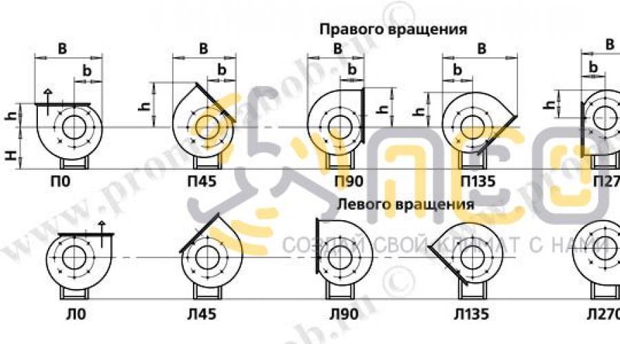
Position of the VRAN fan casing is used. No. 1

| Number fan | Overall dimensions, mm | |||||||||||
| 0 0 | 45 0 | 90 0 | ||||||||||
| B | b | H | h | B | b | H | h | B | b | H | h | |
| VRAN No. 2.5 | 456 | 186 | 240 | 173 | 423 | 190 | 240 | 312 | 390 | 173 | 240 | 270 |
| VRAN No. 2.8 | 515 | 213 | 310 | 193 | 471 | 206 | 310 | 349 | 441 | 193 | 310 | 302 |
| VRAN No. 3.15 | 572 | 236 | 310 | 215 | 521 | 225 | 310 | 388 | 491 | 215 | 310 | 336 |
| VRAN No. 3.55 | 644 | 267 | 350 | 245 | 590 | 256 | 350 | 438 | 557 | 245 | 350 | 377 |
| VRAN No. 4 | 738 | 301 | 390 | 290 | 686 | 310 | 390 | 514 | 641 | 290 | 390 | 437 |
| VRAN No. 4.5 | 831 | 338 | 435 | 325 | 761 | 339 | 435 | 570 | 719 | 325 | 435 | 483 |
| VRAN No. 5 | 913 | 375 | 535 | 338 | 832 | 363 | 535 | 619 | 776 | 338 | 535 | 538 |
| VRAN No. 5,6 | 1020 | 420 | 570 | 375 | 924 | 399 | 570 | 688 | 865 | 375 | 570 | 600 |
| VRAN No. 6.3 | 1140 | 474 | 665 | 420 | 1034 | 442 | 665 | 768 | 973 | 420 | 665 | 667 |
| VRAN No. 7.1 | 1282 | 534 | 745 | 480 | 1167 | 499 | 745 | 869 | 1103 | 480 | 745 | 748 |
| VRAN No. 8 | 1440 | 602 | 795 | 536 | 1304 | 553 | 795 | 972 | 1238 | 536 | 795 | 839 |
| VRAN No. 9 | 1615 | 677 | 890 | 590 | 1467 | 621 | 890 | 1078 | 1379 | 590 | 890 | 938 |
| VRAN No. 10 | 1797 | 751 | 970 | 656 | 1627 | 689 | 970 | 1204 | 1533 | 656 | 970 | 1046 |
| VRAN No. 11.2 | 2004 | 841 | 110 | 735 | 1822 | 764 | 1100 | 1342 | 1716 | 735 | 110 | 1163 |
| VRAN No. 12.5 | 2235 | 947 | 1230 | 810 | 2050 | 869 | 1230 | 1487 | 1905 | 810 | 1230 | 1302 |
| VRAN No. 14 | 2760 | 1170 | 1365 | 965 | - | - | - | - | 2350 | 965 | 1365 | 1590 |
| Number fan | Overall dimensions, mm | |||||||||||
| 135 0 | 270 0 | 315 0 | ||||||||||
| B | b | H | h | B | b | H | h | B | b | H | h | |
| VRAN No. 2.5 | 515 | 202 | 240 | 234 | 390 | 173 | 340 | 186 | 515 | 202 | 340 | 190 |
| VRAN No. 2.8 | 579 | 230 | 310 | 265 | 441 | 193 | 350 | 213 | 579 | 230 | 350 | 206 |
| VRAN No. 3.15 | 644 | 257 | 310 | 296 | 491 | 215 | 410 | 236 | 644 | 257 | 410 | 225 |
| VRAN No. 3.55 | 728 | 290 | 350 | 335 | 557 | 245 | 450 | 267 | 728 | 290 | 450 | 256 |
| VRAN No. 4 | 840 | 326 | 390 | 376 | 641 | 290 | 470 | 301 | 840 | 326 | 470 | 310 |
| VRAN No. 4.5 | 936 | 366 | 435 | 422 | 719 | 325 | 535 | 338 | 936 | 366 | 535 | 339 |
| VRAN No. 5 | 1023 | 404 | 535 | 470 | 776 | 338 | 580 | 375 | 1026 | 406 | 580 | 363 |
| VRAN No. 5.6 | 1143 | 455 | 570 | 525 | 865 | 375 | 665 | 420 | 1143 | 455 | 665 | 399 |
| VRAN No. 6.3 | 1282 | 513 | 665 | 591 | 973 | 420 | 746 | 474 | 1282 | 513 | 746 | 442 |
| VRAN No. 7.1 | 1447 | 578 | 745 | 667 | 1103 | 480 | 845 | 534 | 1447 | 578 | 845 | 500 |
| VRAN No. 8 | 1623 | 651 | 795 | 751 | 1238 | 536 | 895 | 602 | 1623 | 651 | 895 | 553 |
| VRAN No. 9 | 1811 | 733 | 890 | 846 | 1379 | 590 | 1010 | 677 | 1811 | 733 | 1010 | 621 |
| VRAN No. 10 | 2017 | 814 | 970 | 939 | 1533 | 656 | 1100 | 751 | 2017 | 814 | 1100 | 689 |
| VRAN No. 11.2 | 2253 | 911 | 1100 | 1051 | 1716 | 735 | 1250 | 841 | 2254 | 911 | 1250 | 764 |
| VRAN No. 12.5 | 2512 | 1025 | 1230 | 1181 | 1905 | 810 | 1430 | 947 | 2512 | 1025 | 1430 | 869 |
| VRAN No. 14 | - | - | - | - | 2350 | 965 | 1635 | 1170 | - | - | - | - |
Overall and mounting dimensions of VRAN fans (5th version)

| № fan | Connecting dimensions, mm | n | n 1 | n 2 | n 3 | Overall dimensions, mm | ||||||||||||
| A | A 1 | A 2 | IN | IN 1 | AT 2 | D | d | d 1 | t | t 1 | Lmax | L 1 | L 2 | |||||
| 6,3 | 441 | 400 | 470 | 801 | 700 | 830 | 660 | M8 | 9 | 100 | 35 | 8 | 26 | 4 | 7 | 1080 | 222 | 231 |
| 8 | 563 | 300 | 600 | 1009 | 750 | 1047 | 835 | M8 | 9 | 150 | 150 | 8 | 18 | 2 | 5 | 1200 | 282 | 297 |
| 10 | 703 | 450 | 750 | 1269 | 1050 | 1317 | 1050 | M8 | 12 | 150 | 150 | 16 | 24 | 3 | 7 | 1540 | 353 | 366 |
| 12,5 | 877 | 750 | 925 | 1523 | 1500 | 1638 | 1285 | M10 | 12 | 150 | 87,5 | 16 | 34 | 5 | 10 | 1710 | 440 | 455 |
| № fan | Installation dimensions, mm | Flexible side insert: | |||||||||
| WITH | C 1 | C 2 | C 3 | d 2 | d 3 | To | to 1 | to 2 | injection | suction | |
| 6,3 | 980 | 1110 | 245 | - | 12 | 18 | 120 | 140 | 320 | VG-N-6.3 | VG-V-6.3 |
| 8 | 1156 | 1190 | 310 | - | 12 | 18 | 130 | 301 | 294 | VG-N-8 | VG-V-8 |
| 10 | 1456 | 1900 | 446 | - | 12 | 18 | 150 | 381 | 904 | VG-N-10 | VG-V-10 |
| 12,5 | 1645 | 2025 | 550 | 2223 | 15 | 24 | 180 | 525 | 875 | VG-N-12.5 | VG-V-12.5 |
Position of the VRAN fan housing diagram No. 5

| № fan | Overall dimensions, mm | ||||||||||||||
| 0 0 | 45 0 | 90 0 | |||||||||||||
| B | B 1 | b | H | h | B | B 1 | b | H | h | B | B 1 | b | H | h | |
| 6,3 | 1140 | 1736 | 474 | 671 | 426 | 1034 | 1662 | 442 | 671 | 768 | 973 | 1623 | 420 | 671 | 667 |
| 8 | 1440 | 1833 | 602 | 843 | 536 | 1304 | 1746 | 553 | 843 | 972 | 1238 | 1697 | 536 | 843 | 839 |
| 10 | 1797 | 2676 | 751 | 1050 | 656 | 1627 | 2568 | 689 | 1050 | 1204 | 1533 | 2507 | 656 | 1050 | 1046 |
| 12,5 | 2235 | 2918 | 947 | 1230 | 810 | 2050 | 2811 | 869 | 1230 | 1487 | 1905 | 2725 | 810 | 1230 | 1302 |
| № fan | Overall dimensions, mm | ||||||||||||||
| 135 0 | 270 0 | 315 0 | |||||||||||||
| B | B 1 | b | H | h | B | B 1 | b | H | h | B | B 1 | b | H | h | |
| 6,3 | 1282 | 1583 | 513 | 671 | 591 | 973 | 1490 | 420 | 751 | 474 | 1282 | 1839 | 513 | 751 | 442 |
| 8 | 1623 | 1646 | 651 | 843 | 751 | 1238 | 1531 | 536 | 933 | 602 | 1623 | 1967 | 651 | 933 | 53 |
| 10 | 2017 | 2444 | 814 | 1050 | 939 | 1533 | 2286 | 656 | 1150 | 751 | 2017 | 2833 | 814 | 1150 | 689 |
| 12,5 | 2512 | 2655 | 1025 | 1230 | 1181 | 1905 | 2440 | 810 | 1430 | 947 | 2512 | 3117 | 1025 | 1430 | 869 |
Medium-pressure radial industrial fans VRAN are presented in two modifications of impellers and with a wide standard range of R20 wheel diameters. This allows you to select optimal model for any operating mode. Fan capacity - from 300 to 150,000 m³/h, maximum pressure 2600 Pa. Units of this type are used in injection systems and installations where there are size restrictions. Specifications VRAN fans are not inferior to the performance of imported analogues. Strength indicators are confirmed by relevant tests.
Purpose
VRAN fans are installed in standard ventilation, air conditioning and air heating systems; the units are suitable for industrial or residential premises. Particularly effective in installations where there are strict restrictions on the overall dimensions of the fan. Suitable for smoke ventilation.
The following versions of this model are presented:
- N - general industrial;
- F - heat resistant;
- K1 - corrosion-resistant;
- K1Zh - corrosion-heat-resistant;
- B - explosion-proof - according to the 1st design scheme;
- VZh - explosion-proof, heat-resistant - according to the 1st design scheme;
- VK1; VK3 - explosion-proof, corrosion-resistant - according to the 1st design scheme;
- VK1Zh - explosion-proof, corrosion-heat-resistant - according to the 1st design scheme;
- C - earthquake-resistant.
Design
The main element of the fan design is an impeller with backward-curved blades. The wheel is placed in a rotating spiral housing. Special inlet pipe cylindrical placed outside the wheel, which ensures long service life. There is also no inlet flange, which makes the air inlet on the suction side more favorable. There is a separate mechanism to protect the engine from precipitation. The motor is three-phase asynchronous single-speed. VRAN9 models according to the 1st scheme can be equipped with a drive with frequency regulation of the rotation speed. The fans are capable of operating in smoke removal mode or in a combined smoke removal and ventilation mode - such models have motors installed for long-term continuous operation.
terms of Use
VRAN industrial fans are installed outside premises at a distance from places where people are constantly staying. Operation is permitted in temperate, moderately cold and tropical climates when placed in categories 1 and 2. Permissible temperature air - from -45 to +50ºС. If there is a vibration source nearby, the vibration velocity should not exceed 2 mm/s. To reduce noise levels, a noise-insulating casing can be used.
The manufacturer offers the following versions of VRAN fans:
- N - general industrial;
- F - heat resistant;
- K1 - corrosion resistant;
- K1Zh - corrosion-resistant, heat-resistant;
- B - explosion-proof (1st design diagram);
- VZh - explosion-proof, heat-resistant (1st design diagram);
- VK1, VK3 - explosion-proof, corrosion-resistant (1st design diagram);
- VK1Zh - explosion-proof, corrosion-resistant, heat-resistant (1st design scheme);
- C - earthquake-resistant.
VentInform company provides supplies ventilation equipment to all regions of Russia. We offer VRAN6 and VRAN9 fans in the following standard sizes:
- VRAN6 No. 2.5;
- VRAN6 No. 2.8;
- VRAN6 No. 3.15;
- VRAN6 No. 3.55;
- VRAN6 No. 4;
- VRAN6 No. 4.5;
- VRAN6 No. 5;
- VRAN6 No. 5,6;
- VRAN6 No. 6.3;
- VRAN6 No. 7.1;
- VRAN6 No. 8;
- VRAN6 No. 9;
- VRAN6 No. 10;
- VRAN6 No. 11.2;
- VRAN6 No. 12.5;
- VRAN6 No. 14;
- VRAN9 No. 2.5;
- VRAN9 No. 2.8;
- VRAN9 No. 3.15;
- VRAN9 No. 3.55;
- VRAN9 No. 4;
- VRAN9 No. 4.5;
- VRAN9 No. 5;
- VRAN9 No. 5,6;
- VRAN9 No. 6.3;
- VRAN9 No. 7.1;
- VRAN9 No. 8;
- VRAN9 No. 9;
- VRAN9 No. 10;
- VRAN9 No. 11.2;
- VRAN9 No. 12.5;
- VRAN9 No. 14.
VentInform’s partners include leading domestic and foreign manufacturers ventilation equipment, which guarantees high quality products. We offer our clients best prices and the most convenient conditions for purchase.
Purpose and description of the fan Veza VRAN6-071-DU to remove gases.
The fans are certified and have permission for use in explosive and chemically hazardous industries and facilities.
Design and execution
- Typesizes: 400; 450; 500; 560; 630; 710; 800; 900; 1000; 1120; 1250 mm - 1st version;
- Typesizes: 630; 800; 1000; 1250 mm - 5th version;
- 400°C; 600°C - 120 min;
- General industrial;
- Corrosion resistant;
- Explosion-proof;
- The family of air exhaust fans has been expanded - fans operating in general exhaust mode (in addition to the emergency mode of remote control);
- Modification of fans with VFD;
- Use of motors with increased efficiency as required by IE2 or IE3
Veza VRAN6-071-DU fans have a left- or right-hand rotation impeller with specially shaped backward-curved blades that provide high efficiency and low noise.
The spiral housing is rotary. It is possible to operate the fans in the smoke removal mode (SD) and in the combined smoke removal and ventilation mode (SUV). In the latter case, the fans are equipped with motors for long-term permanent job.
The fans are equipped with standard 3-phase asynchronous single-speed motors. For VRAN9 fans according to the 1st design scheme, it is possible to equip them with motors that allow frequency control of the rotation speed.
For housing position P0 and LO for the 1st category of placement (outdoor), protection from atmospheric precipitation ZONT-VRAN is provided (ordered separately as an option).
Climate, operating conditions Veza VRAN6-071-DU
Veza VRAN6-071-DU fans must be installed outside the serviced premises and outside the area of permanent residence of people.
Fans can be operated in moderate conditions (U); temperate and cold (UHL) and tropical (T) climates of the 1st and 2nd categories of placement according to GOST 15150.
- temperature environment
- from minus 45 to +40°С for temperate climates,
- from minus 60 to +40°С for moderate and cold climates,
- from minus 10 to +50°С for tropical climates; - the average vibration velocity of external vibration sources at the fan installation sites is no more than 2 mm/s.
Marking Veza VRAN-DU

Aerodynamic characteristics of VRAN-DU


dimensions

Additional equipment on request
- Thermal and noise insulating casing TShK
- Soft connector COM-VRAN
- Protection ZONT-VRAN
- Cabinet ShSAU
- Vibration isolators
- Reverse flange - FOV - FON
- Frequency converter
- Soft starter
We draw your attention to the fact that the offer is not a public offer. You can find out more on the page