Not quite an ordinary "button". IR proximity sensor. Robot Senses: Sharp GP2Y0A21YK IR Proximity Sensor IR Proximity Sensor
Read also
The sensor is designed to control electrical equipment or to work with a security system. It reacts to the approach of a person or any object in it. Depending on the sensitivity set by the trimming resistor, the operating range can be from several meters to several centimeters.
The circuit is based on the LM567 chip, which is a tone decoder. Since the setting to the decoding frequency depends on the frequency of the built-in generator, and is actually equal to it, this frequency can be used as a pulse source for modulating infrared radiation.
The frequency of the chip's built-in oscillator depends on the RC circuit R7-C2. In this case, pulses can be removed from pin 5 of the microcircuit. Which is what has been done here. Pulses from pin 5 A1 through circuit R4-C3 are supplied to the input of the amplifier using transistors VT1 and VT2, at the output of which (in the collector circuit VT1) the infrared LED HL1 is turned on.
Thus, HL1 serves as an IR signal emitter, and phototransistor VT3 serves as a receiver.
HL1 and VT3 are mutually located so that there is no direct optical connection between them. They are directed in one direction - in that direction, and between them there is an opaque partition, which can be, for example, a table top (for example, HL1 is on the table, and VT3 is under the table).
If a person or some object appears in front of the sensor consisting of HL1 and VT3, the IR beam emitted by the HL1 LED is reflected from its surface and hits the VT3 phototransistor. Since the beam was modulated by pulses from the generator of the A1 microcircuit, photocurrent pulses of the same frequency are formed at the VT3 emitter. They, through the tuning resistor R6, which regulates the sensitivity, and the capacitor C1, are supplied to the input of the decoder of the A1 chip. Since their frequency coincides with the frequency of the generator on R7 and C2, and it cannot be otherwise, the switch at the output of microcircuit A1 opens, it goes out as a collector to its pin 8. This creates a current based on transistor VT4. It opens and the voltage on its collector rises to the supply voltage.
The nominal supply voltage for the LM567CN chip is 5V, and the entire circuit here is powered by 12V. Therefore, the supply voltage of the microcircuit is reduced and stabilized at the 5U level by the parametric stabilizer VD2-R11.
The domestically produced AL123A IR LED can be replaced with almost any IR LED designed for remote control systems.
The ratings R7 and C2 may differ significantly from those indicated in the diagram. This will have virtually no effect on the operation of the sensor, because the same circuit R7-C2 works both in the reference frequency generator for the phase detector of the decoder of the A1 chip, and in the generator for modulating the IR radiation of the LED. That is, the transmission and reception frequencies coincide in any case, because they are generated by the same generator.
All capacitors used must be designed for a maximum voltage not lower than the supply voltage.
The sensitivity of the sensor (response range) can be adjusted in two ways. In the first case, this is a tuning resistor R6, which regulates the sensitivity of the decoder. In the second case, this is the selection of the resistance of resistor R5, which limits the current through infrared light diode You should not choose this resistor less than 3-4 Ohms.
Literature:
- “Two automatic lighting control systems.” and. Radio, 2008, No. 3, p. 37.
Gorchuk N.V.
Robots, like death, all people really need sense organs to navigate in space. The Sharp GP2Y0A21YK infrared rangefinder is very suitable for this role if you need to avoid collisions with obstacles or know approximately where this obstacle is located.
By the way, you may already have one of the robots at home that uses similar sensors. These are almost all sane Chinese robot vacuum cleaners and, I believe, many Roomba models. And probably many others.
And if these sensors have a place in more or less serious technology, then we will find a use for them, right?
In order not to prevaricate, I will say right away: I ordered these sensors not just to play around with. On the contrary, from the very beginning I knew that they would be useful to me to make an interactive lamp that changes the intensity of the glow depending on the position of the palm above it.
Of course, reality made its own adjustments in the end. In other words, it now has five modes: night light, dimmable lamp, thermometer, “northern lights” with manual adjustment and automatic northern lights.

And in addition - a couple of service functions: turning on and off the background and overhead lighting in the room.
Here's how it works:
Well, now is the time to talk in more detail about the sensor, thanks to which everything happened.

As I said at the very beginning, the Sharp GP2Y0A21YK is an infrared rangefinder. This means that it is equipped with an IR emitter and an IR receiver: the first serves as the source of the beam, the reflection of which is caught by the second. At the same time, the IR rays of the sensor are invisible to the human eye (although you can discern a red flicker if you look into the sensor) and at this intensity are harmless.
They also have no effect on domestic animals.
According to the characteristics:
- Supply voltage: 5V
- Maximum current consumption: 40 mA (typical - 30 mA)
- Operating range: 10 cm - 80 cm
The disadvantages are a shorter range (the HC-SR04 has about 4 m) and dependence on external interference, including some types of lighting. For example, I have come across mentions that sunlight may affect sensor readings.

The sensor is supplied in a spartan kit, i.e. the sensor itself and a cable with a connector for connecting to the sensor. On the other side there are simply tinned wires, which is not very convenient for use with Arduino Uno, but is quite suitable for controllers without soldered connectors. Since I planned to use the sensor with Arduino Pro Mini, it was quite possible suitable option- I simply soldered the wires into the breadboard.

The wires differ in color: yellow - signal, black - ground, red - power plus (+5V).
The sensor output is analog (although for some reason the datasheet says digital). That is, the voltage on it is proportional to the distance to the obstacle. However, as in the case of ultrasound, for the sensor there is a difference between different types obstacles.

In this regard, in the datasheet, Sharp provides data using Kodak reference cards with a reflectivity of 90% as reflectors. Judging by it, at 20 cm the sensor produces 1.3V.
Let's compare with my experimental data:

Let me remind you that the Arduino analog input operates in the range 0V - 5V and has 1024 steps, hence the calculation: (5/1024)*(sensor readings). So if you take into account the fact that everything is done with your own (shaky) hands, then the readings fit well into the characteristics of the sensor. And at the same time you can see that the black surface makes its own adjustments.
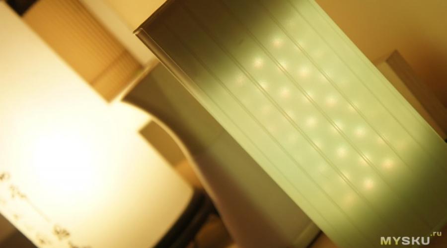
So it shines 
At the same time, as the attentive reader has noticed, there are specifics. The point is that when the obstacle is closer to the lower limit of the range (10 cm), the sensor begins to consider that the obstacle, on the contrary, is moving away (when I covered it with my hand, the readings were fixed at 345).
It looks something like this:

Hence the conclusion: although the datasheet is quite adequate for many purposes, sometimes it makes sense to conduct experiments so that later it will not be excruciatingly painful. And this is especially true if the sensor is somewhat recessed (or covered with IR-transparent material), which means it can receive reflections from walls or other elements of the housing.
For example, I was faced with the fact that Evlampia, having been installed in its regular place after successful “desktop” tests, began to go crazy. At first I thought that power supply interference was to blame and even installed a couple of capacitors (10 µF and 0.1 µF) in parallel with the sensor power supply, pulled the Arduino analog input to zero through a 10 kOhm resistor and even bought a surge protector socket.
But when this did not help, he returned to the table again, where he twisted the sensor different sides and saw that in fact, even if the distance to the nearest obstacle is more than 80 cm, the sensor readings change noticeably. So if your charges are inadequate, check the actual readings in real conditions.
Here, for example, is an elementary sketch that, firstly, displays sensor readings at half-second intervals, and, secondly, lights up the Arduino LED if the readings fall in the range from 100 to 200:
// Yellow - A0, Black - ground, Red - +5V unsigned int l; void setup() ( Serial.begin(9600); pinMode(A0, INPUT); pinMode(13, OUTPUT); l = 0; ) void loop() ( l = analogRead(A0); Serial.println(l); delay(1000); if (l > 100 && l< 200) { digitalWrite(13, HIGH); } else { digitalWrite(13, LOW); } }
To sum it up, the sensor, although a little finicky, is very easy to use and relatively cheap.
It can be used in robots, as well as for intersection control doorways, in some interactive devices controlled by gestures and in something else that your imagination suggests.
I'm planning to buy +33 Add to favorites I liked the review +38 +67In order to attract clients or customers, you can make an automated advertising stand or display window in which the lighting will turn on when a person approaches it. An attempt to use standard motion sensors for this was unsuccessful because they respond to movement, not presence.
IR proximity sensor
Yes, when a person approaches, the motion sensor will turn on the advertisement, but if the person stops and stands looking at the advertising stand or display window, the advertisement will turn off because there will be no movement. We need a sensor that reacts not to movement, but to the fact that a person is standing in front of it. For example, an IR reflectance sensor, the diagram of which is given here. The sensor consists of an “optical pair” from the TV remote control system, an infrared LED HL1 and a resonant photodetector HF1 tuned to a frequency of 36 kHz.
The LED and photodetector are directed in one direction to the place in front of the advertising stand or display case. They must be located so that the light from the NI does not directly hit HF1, but only when reflected from an obstacle located in front of the sensor. That is, there should be an opaque partition between them.
The multivibrator on elements D1.3 and D1.4 generates pulses with a frequency of 36 kHz (exactly this frequency is set by selecting resistance R7). These pulses arrive at the base of the switch on transistor VT3. An infrared LED NI is included in its collector circuit. Light-emitting diode
emits flashes of IR light, repeating at a frequency of 36 kHz, and the luminous intensity of these flashes depends on the current through the LED, the value of which is set by selecting the resistance of resistor R5.
If a person stands in front of the sensor, flashes of light emitted by the NI LED are reflected from it and fall on the HF1 photodetector. In this case, the output switch of the photodetector opens and its output (pin 3) will be logical zero. Transistor VT1 opens and charges capacitor C2. The voltage on it is a logical unit. The output D1.2 is also a logical one.
Transistor VT2 opens and relay K1 with its contacts (not shown in the diagram) turns on the lighting of the stand or display case. When a person steps aside, the light does not turn off immediately, but after 23 seconds (time for discharge C2 through R3). This is necessary so that the light does not blink when a person moves near the advertising stand or display case. The sensitivity of the sensor (range to a person) depends on the resistance R5.
The “Tyap-Blyap” channel presented for consideration a kit set for self-made from finished parts infrared proximity sensor. According to the channel's host, this is an irreplaceable thing in the house. The board is painted, the details are indicated. There are instructions with a diagram. Unfortunately, there is no description in Russian. The main thing is that the elements are signed.
You can buy it in this Chinese store.
This sensor reacts when an object approaches a certain distance. The relay will operate and turn the circuit on or off. The wizard will place the elements on the board, perform soldering and check the proximity sensor in operation. Before starting, check the resistor values. A convenient device is used for this.
Almost the elements are inserted onto the board. All that remains is to solder the microcircuit and you can start testing. All is ready. All that remains is to wash the board.
Device characteristics. The supply voltage is 12 volts, the load can be connected from 250 volts, 10 amperes. Everything is ready for testing. Everything is connected. The load will be used light at 12 volts. It is powered from a separate lead battery. The board's idle mode consumption is only 26 milliamps. When an obstacle appears, the light comes on. The time relay works for some time and can withstand the load. Then it turns off. The operating time is regulated by a trimming resistor. Let's try to unscrew it clockwise. Now the load is switched off almost simultaneously with the removal of the obstacle. Let's try, on the contrary, to increase the operating time. You can set the time much longer than shown in the test.
Regarding the operating distance. On hand infrared sensor reacts when approaching at a distance of approximately 10 centimeters.
If we take a thicker object, for example a piece of plywood. The device was triggered when approaching 16 centimeters. The question arises: what affects the distance? The volume of the object, its thickness? A piece of paper was triggered at a distance of 12 centimeters.
The aluminum sheet reacted when approaching 30 centimeters. Let's try with a mirror. The mirror worked at 50 cm. What if you take it further away and try to move objects? The sensing distance has increased by another decimeter.
Source: youtu.be/ASsk3xXDMuU
Infrared sensor

The figure above is a diagram of a simple infrared sensor that allows you to signal when something is approaching it.
The operating range of the infrared sensor is about a meter, this distance depends on design feature infrared transceiver part of the device, which is made in the form of a HOA1405 module. This is a module with an infrared LED and a phototransistor built inside, the design of the module is shown in the figure below. 
The emitted infrared light bounces off something and hits a phototransistor, which is connected to the legendary and ubiquitous NE555 timer, which operates in monostable trigger mode. When a certain resistance of the phototransistor is reached, which depends on the intensity of the received reflected infrared signal, the trigger on the NE555 changes its state and a sound is heard from the tweeter, and the LED also lights up for two minutes. The alarm time depends on elements R4 and C2. It is permissible to use any other module as a transceiver module, or to install the LED and phototransistor separately, however, if used separately, it is necessary to provide such a design so that the phototransistor is not illuminated by the LED. The scheme is simple, easy to repeat and does not require configuration. You can even use it for compactness wall-mounted installation. Such a sensor can be used, for example, in burglar alarm, in systems for contactless activation of something, etc., it is a matter of imagination and the needs of the radio amateur.
Unfortunately, it will not be used yet, since it came to me later than planned (the reason is not the speed of delivery, but some other reasons) and I had to use a much more expensive solution.
There are different switches and switches.
There are ordinary ones that everyone has at home. To turn them on or switch, you need to click on them.
There are ones with a touch sensor, you don’t need to press them, just touch them.
And there are non-contact ones, but not in terms of the absence of contacts (although one does not interfere with the other), but in the absence of the need to even touch the switch, you just need to bring your hand to it.
It is the latter type of such devices that will be discussed further.
I’ll probably start, as always, with a description and photo of what I received, and in the process I’ll tell you what it is, why and what approximate analogues there are of this device.
It came in a neat box, the switch itself (or rather the switch) was in a transparent bag, but I took it off before taking the photo. 
There was inside the bag.
The actual switch.
Mounting kit, two plastic stoppers and two screws.
Instructions for English language, although it is not particularly needed for this device, since it does not have any adjustment controls, and the outputs are labeled on the back of the device itself.
A piece of paper I don't understand. 
Instructions, maybe someone will find them useful :) 
The button itself is made of very high quality, the metal is strong, although thin, very similar to stainless steel, the plastic parts fit well.
And it looks quite nice, only the Exit inscription is annoying, I’ll write why later. 
There are 5 wires on the back.
Red and black, respectively, are plus and minus power, everything corresponds to generally accepted markings (there are exceptions).
Yellow - common relay contact
Green - normally open contact
White - normally closed contact.
The wires are not very long, about 15cm. 
So we gradually got to the insides.
The board in the device is double-sided, the purpose of the wires is also written on the back, which is very nice, since the piece of paper pasted on the back may well come off, be damaged, etc.
The back cover is not sealed, but it fits quite well, but the hole for the wires to exit is made with a margin, so the protection class is indicated only for the front panel. 
Logically, there should be a photo of the insides next. It will be, but first I will make a small lyrical digression.
To begin with, what types of proximity switches are there?
1. Capacitive, require touching or bringing your hand to a very close distance. Probably the simplest and cheap solution. I had one involving such a sensor.
2. Radio frequency, operating on the Doppler principle. The most expensive sensors.
3. Sensors based on the reflection of IR radiation. Simple and inexpensive, but a compromise option.
And now the advantages and disadvantages.
Capacitive, relatively inexpensive, but touching the surface is desirable, may not work correctly in the event of electromagnetic interference.
Radio frequency, operate at a very high frequency, about 24 GHz. They are complex and, accordingly, expensive, but are less afraid of interference, are not afraid of surface contamination, and can work through opaque plastic.
Infrared, simple design, the range is comparable to radio frequencies, but may decrease if the surface has heavy pollution and do not work through materials that are opaque in the IR range.
Now I will try to explain why I use such switches.
In addition to writing reviews and soldering boards, I install automatic sliding doors. and these doors do not always include a motion sensor.
And since I install such doors at enterprises, they operate sanitary standards, for which it is desirable (and sometimes mandatory, for example in operating rooms and toilets) to use door opening activators with contactless control (there are even special devices where you need to insert your foot so that the contact will work).
Until recently, I used sensors from the Belgian company Bea. For example 
The cost of one such sensor is (if I’m not confusing anything) about $130.
And often you need two sensors for one door.
It should be noted that these sensors are not anti-vandal, the reviewed one is made more robustly, but is also not considered vandal-proof.
So I gradually got to the point of showing how the IR sensor works inside.
First, I’ll show you the place where the board is placed, the holes for transmitting and receiving IR radiation are clearly visible, they are made so that the IR receiver sees only reflected radiation.
The board itself will not work.
By the way, a rubber seal around the perimeter of the metal would be nice, but expensive radio frequency ones don’t have it either. 
And now myself printed circuit board devices.
It shows -
IR LED.
IR photodetector, these are usually used in various radio equipment having remote control, operating frequency 38 KHz (measured).
The relay, its parameters correspond to the parameters specified in the instructions.
Connector for connecting wires.
The power input is protected in the form of a self-resetting fuse and a diode that protects against connecting power to the wrong polarity. Next there is a 5 Volt power stabilizer; there are no electrolytic capacitors, which only increases reliability.
Four bi-color LEDs. Shines red in normal mode and blue when triggered.
Control chip, small, 6 legs, in SOT23 package. 
For control, a microcircuit is used on which it says 02En, I found it on the Internet, but I’m not sure that this is it, since the page is in Chinese and looks like some kind of incomprehensible page trading platform or forum.
It not only constantly generates pulses to control the LED, but forms certain sequences of bursts of pulses, and a photodetector is connected to it accordingly.
As a result, obstacle recognition is quite correct; it does not respond to the IR remote control, as well as to strong illumination from an incandescent lamp (but this is the merit of the photodetector). 
Naturally, I measured the current consumption in standby and operating mode.
In standby mode it consumes 27mA. Power supply 12 Volt. 
In active mode, a little more, 38mA, since the relay is turned on. 
In standby mode, the backlight is red, a little uneven, but maybe that’s how it was intended. 
In active mode, the backlight is blue, but since a matte light diffuser is used, it is not very annoying. 
The operating range is about 8cm by hand and about 15cm from a sheet of white paper.
It triggers very clearly even with a relatively quick hand movement; after triggering, it remains in active mode for about two seconds, after which it goes into standby mode.
Doesn't work on relatively thin objects. 
The design is quite thin, most of it is recessed, as it is designed for insertion into a wall/panel. 
Just in case, I measured the main dimensions, in case it comes in handy for someone. 
As I wrote above, the power supply is 12 Volts, which hints that the device is intended for use in security systems, and the Exit sign says the same thing.
Systems for industrial automation have a standard 24 Volt power supply, and can also operate from direct current and from variable.
I think that with some simple modifications the button can be used with industrial automation systems.
The button could be very convenient in various fields application, but the inscription is annoying, in my opinion it would be possible to suggest either different variants inscriptions, or provide stickers with various inscriptions in the kit.
Scope of application -
Access control devices.
Control of door opening in premises where it is necessary to give a command to open without touching, grocery stores, operating rooms, clean rooms, toilets, etc.
Just places where such control can be convenient, for example in the kitchen (with appropriate decorative modifications) to turn on the lighting.
In general, when I wrote this review, I had a feeling of slight deja vu; I described similar impressions of the device in the review. In particular, I really liked the quality of workmanship and the rather thoughtful and reliable-looking circuitry.
On the Internet I came across at least two options for homemade implementation similar device, one on the LM567CN chip, as well as on the . Last option I collected it and I use it successfully, if you are interested, I can do a review somehow.
Summary.
Pros.
Price.
Good appearance.
High-quality manufacturing and quite thoughtful design.
Minuses.
I would like to sealing gum around the perimeter for sealing.
Since the device can be used not only as an exit button, I would like to have options for changing the label.
My opinion. A completely worthy and simple replacement for RF proximity switches, and also does not create RF radiation.
This product was provided free of charge for review and testing by eachbuyer.
I think that a review of this device might be useful. I look forward to your questions and comments.
If I forgot to mention something, write me and I’ll add it.
P.S. By adding a cheap microcircuit (and possibly one resistor and capacitor), you can convert the device into a bistable one, i.e. They raised their hand, turned it on, raised it again, turned it off. The cost of conversion is about 20 cents, the chip is HEF4013BP.
Now the device works as an analogue of a non-fixed button (like an exit button in intercoms, although this sensor is made for such an application).
Perhaps there will be another review with a similar modification :).