Brief description of the operation of a thermal power plant. Use of heat from mini-CHP. The operating principle of thermal power plants. Short description
Read also
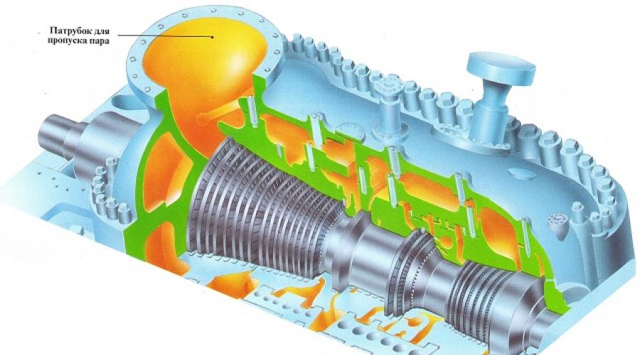
The impeller blades of this steam turbine are clearly visible.
Thermal power plant(CHP) uses the energy released by burning fossil fuels - coal, oil and natural gas - to convert water into steam high pressure. This steam, having a pressure of about 240 kilograms per square centimeter and a temperature of 524°C (1000°F), drives the turbine. The turbine spins a giant magnet inside a generator, which produces electricity.
Modern thermal power plants convert about 40 percent of the heat released during fuel combustion into electricity, the rest is discharged into environment. In Europe, many thermal power plants use waste heat to heat nearby homes and businesses. Combined heat and power generation increases the energy output of the power plant by up to 80 percent.
Steam turbine plant with electric generator

A typical steam turbine contains two groups of blades. High-pressure steam coming directly from the boiler enters the flow path of the turbine and rotates the impellers with the first group of blades. The steam is then heated in the superheater and again enters the turbine flow path to rotate impellers with a second group of blades, which operate at a lower steam pressure.
Sectional view

A typical thermal power plant (CHP) generator is driven directly by a steam turbine, which rotates at 3,000 revolutions per minute. In generators of this type, the magnet, also called the rotor, rotates, but the windings (stator) are stationary. The cooling system prevents the generator from overheating.
Power generation using steam

At a thermal power plant, fuel burns in a boiler, producing a high-temperature flame. The water passes through the tubes through the flame, is heated and turns into high-pressure steam. The steam spins a turbine, producing mechanical energy, which a generator converts into electricity. After leaving the turbine, the steam enters the condenser, where it washes the tubes with cold running water, and as a result turns back into liquid.
Oil, coal or gas boiler

Inside the boiler
The boiler is filled with intricately curved tubes through which heated water passes. The complex configuration of the tubes allows you to significantly increase the amount of heat transferred to the water and, as a result, produce much more steam.
ORGANIZATIONAL AND PRODUCTION STRUCTURE OF THERMAL POWER PLANTS (TPP)
Depending on the power of the equipment and the schemes of technological connections between the stages of production at modern thermal power plants, they distinguish between workshop, non-shop and block-shop organizational and production structures.
Shop organizational and production structure provides for the division of technological equipment and the territory of thermal power plants into separate areas and assigning them to specialized units - workshops, laboratories. In this case the main structural unit is a workshop. Depending on their participation in production, workshops are divided into main and auxiliary. In addition, thermal power plants can also include non-industrial farms (housing and subsidiary farms, kindergartens, holiday homes, sanatoriums, etc.).
Main workshops are directly involved in energy production. These include fuel and transport, boiler, turbine, electrical and chemical shops.
The fuel transport workshop includes railway and fuel supply sections with a fuel warehouse. This workshop is organized at power plants that burn solid fuel or fuel oil when delivered by rail.
The boiler shop includes areas for supplying liquid or gaseous fuel, dust preparation, and ash removal.
The turbine shop includes: heating department, central pumping station and water management.
With two workshops production structure, as well as at large thermal power plants, the boiler and turbine shops are combined into a single boiler-turbine shop (BTS).
The electrical workshop is in charge of: all electrical equipment of thermal power plants, an electrical laboratory, an oil production facility, and an electrical repair shop.
The chemical workshop includes a chemical laboratory and chemical water treatment.
Auxiliary workshops serve the main production. These include: a centralized repair shop, a repair and construction shop, a thermal automation and communications shop.
Non-industrial farms are not directly related to energy production and serve the household needs of thermal power plant workers.
Shopless organizational and production structure provides for the specialization of divisions in performing basic production functions: operation of equipment, its repair maintenance, technological control. This leads to the creation of production services instead of workshops: operation, repairs, control and improvement of equipment. In turn, production services are divided into specialized areas.
Creation block-shop organizational and production structure due to the emergence of complex energy units-blocks. The unit's equipment carries out several phases of the energy process - burning fuel in a steam generator, generating electricity in a turbogenerator, and sometimes converting it in a transformer. In contrast to the workshop structure, the main production unit of a power plant in a block-shop structure is the blocks. They are included in the CTC, which are engaged in the centralized operation of the main and auxiliary equipment boiler and turbine units. The block-shop structure provides for the preservation of the main and auxiliary workshops that take place in the workshop structure, for example, the fuel and transport workshop (FTS), chemical, etc.
All types of organizational and production structure provide for production management on the basis of unity of command. At each thermal power plant there is administrative, economic, production, technical and operational dispatch management.
The administrative and economic head of the thermal power plant is the director, the technical manager is the chief engineer. Operational dispatch control is carried out by the duty engineer of the power plant. In operational terms, he is subordinate to the duty dispatcher of the EPS.
The name and number of structural divisions, and the need to introduce individual positions are determined depending on the standard number of industrial production personnel of the power plant.
The indicated technological, organizational and economic features of electric power production affect the content and tasks of managing the activities of energy enterprises and associations.
The main requirement for the electric power industry is a reliable and uninterrupted power supply to consumers and coverage of the required load schedule. This requirement is transformed into specific indicators that evaluate the participation of the power plant and network enterprises in the implementation of the production program of energy associations.
The power plant is ready to bear the load, which is set by the dispatch schedule. For network enterprises, a repair schedule for equipment and structures is established. The plan also specifies other technical and economic indicators: specific fuel consumption at power plants, reduction of energy losses in networks, financial indicators. However manufacturing program energy enterprises cannot be strictly determined by the volume of production or supply of electrical energy and heat. This is impractical due to the exceptional dynamics of energy consumption and, accordingly, energy production.
However, the volume of energy production is an important calculation indicator that determines the level of many other indicators (for example, cost) and the results of economic activities.
The energy hidden in fossil fuels - coal, oil or natural gas - cannot be immediately obtained in the form of electricity. The fuel is first burned. The released heat heats the water and turns it into steam. The steam rotates the turbine, and the turbine rotates the generator rotor, which generates, i.e. produces, electric current.
Scheme of operation of a condensing power plant.

Slavyanskaya TPP. Ukraine, Donetsk region.
This entire complex, multi-stage process can be observed at a thermal power plant (TPP), equipped with energy machines that convert the energy hidden in organic fuel (oil shale, coal, oil and its derivatives, natural gas) into electrical energy. The main parts of a thermal power plant are a boiler plant, a steam turbine and an electric generator.
Boiler plant- a set of devices for producing water vapor under pressure. It consists of a firebox in which organic fuel is burned, a combustion space through which combustion products pass into chimney, and a steam boiler in which water boils. The part of the boiler that comes into contact with the flame during heating is called the heating surface.
There are 3 types of boilers: smoke-fired, water-tube and once-through. Inside combustion boilers there is a series of tubes through which combustion products pass into the chimney. Numerous smoke tubes have a huge heating surface, as a result of which they make good use of fuel energy. The water in these boilers is between the smoke tubes.
IN water tube boilers- it’s the other way around: water is released through the tubes, and hot gases are passed between the tubes. The main parts of the boiler are the firebox, boiling tubes, steam boiler and superheater. The steam formation process takes place in the boiling tubes. The steam generated in them enters the steam boiler, where it is collected in its upper part, above boiling water. From the steam boiler, steam passes into the superheater and is further heated there. Fuel is poured into this boiler through the door, and the air necessary for combustion of the fuel is supplied through another door into the ash pit. Hot gases rise upward and, bending around the partitions, travel the path indicated in the diagram (see figure).
IN once-through boilers The water is heated in long coil pipes. Water is supplied to these pipes by a pump. Passing through the coil, it completely evaporates, and the resulting steam is superheated to the required temperature and then exits the coils.
Boiler installations operating with intermediate superheating of steam are an integral part of the installation called power unit"boiler - turbine".
In the future, for example, to use coal from the Kansk-Achinsk basin, large thermal power plants with a capacity of up to 6400 MW with power units of 800 MW each will be built, where boiler plants will produce 2650 tons of steam per hour with a temperature of up to 565 °C and a pressure of 25 MPa.
The boiler plant produces high-pressure steam, which goes to the steam turbine - the main engine of the thermal power plant. In the turbine, the steam expands, its pressure drops, and the latent energy is converted into mechanical energy. The steam turbine drives the rotor of a generator, which produces electric current.
IN major cities most often built combined heat and power plants(CHP), and in areas with cheap fuel - condensing power plants(IES).
A thermal power plant is a thermal power plant that produces not only electrical energy, but also heat in the form hot water and a couple. The steam leaving the steam turbine still contains a lot of thermal energy. At a thermal power plant, this heat is used in two ways: either the steam after the turbine is sent to the consumer and does not return back to the station, or it transfers heat in the heat exchanger to water, which is sent to the consumer, and the steam is returned back to the system. Therefore, CHP has a high efficiency, reaching 50–60%.
There are CHP heating and industrial types. Heating CHP plants heat and supply residential and public buildings hot water, industrial - supply industrial enterprises with heat. Steam is transmitted from thermal power plants over distances of up to several kilometers, and hot water is transmitted over distances of up to 30 kilometers or more. As a result, thermal power plants are being built near large cities.
A huge amount of thermal energy is used for district heating or centralized heating of our apartments, schools, and institutions. Before the October Revolution district heating there were no houses. Houses were heated by stoves, which burned a lot of wood and coal. District heating in our country began in the first years of Soviet power, when, according to the GOELRO plan (1920), the construction of large thermal power plants began. The total capacity of thermal power plants in the early 1980s. exceeded 50 million kW.
But the main share of electricity generated by thermal power plants comes from condensing power plants (CPS). In our country they are more often called state district electric power plants (SDPPs). Unlike thermal power plants, where the heat of the steam exhausted in the turbine is used for heating residential and industrial buildings, at IES, steam exhausted in engines (steam engines, turbines) is converted by condensers into water (condensate), which is sent back to the boilers for reuse. CPPs are built directly near water supply sources: lakes, rivers, seas. The heat removed from the power plant with cooling water is irretrievably lost. The efficiency of IES does not exceed 35–42%.
Wagons with finely crushed coal are delivered to the high overpass day and night according to a strict schedule. A special unloader tips the wagons and the fuel is poured into the bunker. The mills carefully grind it into fuel powder, and it flies into the furnace of the steam boiler along with the air. The flames tightly cover the bundles of tubes, in which the water boils. Water vapor is formed. Through pipes - steam lines - steam is directed to the turbine and hits the turbine rotor blades through nozzles. Having given energy to the rotor, the exhaust steam goes to the condenser, cools and turns into water. Pumps supply it back to the boiler. And the energy continues its movement from the turbine rotor to the generator rotor. In the generator its final transformation takes place: it becomes electricity. This is where the IES energy chain ends.
Unlike hydroelectric power stations, thermal power plants can be built anywhere, and thereby bring the sources of electricity closer to the consumer and distribute thermal power plants evenly throughout the economic regions of the country. The advantage of thermal power plants is that they operate on almost all types of organic fuel - coal, shale, liquid fuel, natural gas.
The largest condensing thermal power plants in Russia include Reftinskaya (Sverdlovsk region), Zaporozhye (Ukraine), Kostroma, Uglegorskaya (Donetsk region, Ukraine). The power of each of them exceeds 3000 MW.
Our country is a pioneer in the construction of thermal power plants, the energy of which comes from atomic reactor(cm.
What is it and what are the operating principles of thermal power plants? General definition Such objects sound approximately as follows - these are power plants that process natural energy into electrical energy. Fuel of natural origin is also used for these purposes.
The operating principle of thermal power plants. Short description
To date greatest distribution received precisely at such objects it is burned which releases thermal energy. The task of thermal power plants is to use this energy to produce electrical energy.
The operating principle of thermal power plants is not only the generation but also the production of thermal energy, which is also supplied to consumers in the form of hot water, for example. In addition, these energy facilities generate about 76% of all electricity. This widespread use is due to the fact that the availability of fossil fuels for the operation of the station is quite high. The second reason was that transporting fuel from the place of its extraction to the station itself is a fairly simple and streamlined operation. The operating principle of thermal power plants is designed in such a way that it is possible to use the waste heat of the working fluid for its secondary supply to the consumer.
Separation of stations by type
It is worth noting that thermal stations can be divided into types depending on what kind of heat they produce. If the principle of operation of a thermal power plant is only to produce electrical energy (that is, it does not supply thermal energy to the consumer), then it is called condensing power plant (CES).

Facilities intended for the production of electrical energy, for the supply of steam, as well as the supply of hot water to the consumer, have steam turbines instead of condensing turbines. Also in such elements of the station there is an intermediate steam extraction or a backpressure device. The main advantage and operating principle of this type of thermal power plant (CHP) is that waste steam is also used as a heat source and supplied to consumers. This reduces heat loss and the amount of cooling water.
Basic operating principles of thermal power plants
Before moving on to considering the principle of operation itself, it is necessary to understand what kind of station we are talking about. Standard device of such objects includes a system such as intermediate superheating of steam. It is necessary because the thermal efficiency of a circuit with intermediate superheating will be higher than in a system without it. If we talk in simple words, the operating principle of a thermal power plant with such a scheme will be much more efficient with the same initial and final specified parameters than without it. From all this we can conclude that the basis of the station’s operation is organic fuel and heated air.

Scheme of work
The operating principle of the thermal power plant is constructed as follows. The fuel material, as well as the oxidizer, the role of which is most often played by heated air, is fed in a continuous flow into the boiler furnace. Substances such as coal, oil, fuel oil, gas, shale, and peat can act as fuel. If we talk about the most common fuel in the territory Russian Federation, then it is coal dust. Further, the operating principle of thermal power plants is constructed in such a way that the heat generated by burning fuel heats the water located in steam boiler. As a result of heating, the liquid is converted into saturated steam, which enters the steam turbine through the steam outlet. The main purpose of this device at the station is to convert the energy of the incoming steam into mechanical energy.

All elements of the turbine that can move are closely connected to the shaft, as a result of which they rotate as a single mechanism. To make the shaft rotate, a steam turbine transfers the kinetic energy of steam to the rotor.
Mechanical part of the station
The design and principle of operation of a thermal power plant in its mechanical part is associated with the operation of the rotor. The steam that comes from the turbine has very high pressure and temperature. This creates a high internal energy steam, which comes from the boiler to the turbine nozzles. Jets of steam passing through the nozzle in a continuous stream, with high speed, which is most often even higher than the sound level, affects the turbine blades. These elements are rigidly fixed to the disk, which, in turn, is closely connected to the shaft. At this point in time, the mechanical energy of the steam is converted into the mechanical energy of the rotor turbines. If we talk more precisely about the principle of operation of thermal power plants, then the mechanical impact affects the rotor of the turbogenerator. This is due to the fact that the shaft of a conventional rotor and generator are tightly coupled together. And then a rather well-known, simple and clear process converting mechanical energy into electrical energy in a device such as a generator.

Steam movement after the rotor
After the water vapor passes the turbine, its pressure and temperature drop significantly, and it enters the next part of the station - the condenser. Inside this element, the vapor is converted back into liquid. To perform this task, there is cooling water inside the condenser, which enters there through pipes passing inside the walls of the device. After the steam is converted back into water, it is pumped out by a condensate pump and enters the next compartment - the deaerator. It is also important to note that the pumped water passes through regenerative heaters.
The main task of the deaerator is to remove gases from the incoming water. Simultaneously with the cleaning operation, the liquid is heated in the same way as in regenerative heaters. For this purpose, the heat of the steam is used, which is taken from what goes into the turbine. The main purpose of the deaeration operation is to reduce the oxygen and carbon dioxide content in the liquid to acceptable values. This helps reduce the rate of corrosion on the paths through which water and steam are supplied.

Coal stations
There is a high dependence of the operating principle of thermal power plants on the type of fuel used. From a technological point of view, the most difficult substance to implement is coal. Despite this, raw materials are the main source of power at such facilities, the number of which is approximately 30% of the total share of stations. In addition, it is planned to increase the number of such objects. It is also worth noting that the number of functional compartments required for the operation of the station is much greater than that of other types.
How do thermal power plants run on coal fuel?
In order for the station to operate continuously, coal is constantly brought in along the railway tracks, which is unloaded using special unloading devices. Then there are elements such as through which unloaded coal is supplied to the warehouse. Next, the fuel enters the crushing plant. If necessary, it is possible to bypass the process of delivering coal to the warehouse and transfer it directly to the crushers from unloading devices. After passing this stage, the crushed raw materials enter the raw coal bunker. The next step is to supply the material through feeders to the pulverized coal mills. Next, the coal dust, using a pneumatic transportation method, is fed into the coal dust bunker. Along this path, the substance bypasses elements such as a separator and a cyclone, and from the hopper it already flows through the feeders directly to the burners. The air passing through the cyclone is sucked in by the mill fan and then fed into the combustion chamber of the boiler.

Further, the gas movement looks approximately as follows. The volatile substance formed in the chamber of the combustion boiler passes sequentially through such devices as the gas ducts of the boiler plant, then, if a steam intermediate superheater system is used, the gas is supplied to the primary and secondary superheater. In this compartment, as well as in the water economizer, the gas gives up its heat to heat the working fluid. Next, an element called an air superheater is installed. Here the thermal energy of the gas is used to heat the incoming air. After passing through all these elements, the volatile substance passes into the ash collector, where it is cleaned of ash. After this, smoke pumps draw the gas out and release it into the atmosphere using a gas pipe.
Thermal power plants and nuclear power plants
Quite often the question arises about what is common between thermal power plants and whether there are similarities in the operating principles of thermal power plants and nuclear power plants.
If we talk about their similarities, there are several of them. Firstly, both of them are built in such a way that for their work they use a natural resource that is fossil and excreted. In addition, it can be noted that both objects are aimed at generating not only electrical energy, but also thermal energy. The similarities in operating principles also lie in the fact that thermal power plants and nuclear power plants have turbines and steam generators involved in the operation process. Further there are only some differences. These include the fact that, for example, the cost of construction and electricity obtained from thermal power plants is much lower than from nuclear power plants. But, on the other hand, nuclear power plants do not pollute the atmosphere as long as the waste is disposed of correctly and no accidents occur. While thermal power plants, due to their operating principle, constantly emit harmful substances into the atmosphere.
Here lies the main difference in the operation of nuclear power plants and thermal power plants. If in thermal objects the thermal energy from fuel combustion is most often transferred to water or converted into steam, then nuclear power plants energy comes from the fission of uranium atoms. The resulting energy is used to heat a variety of substances and water is used here quite rarely. In addition, all substances are contained in closed, sealed circuits.
District heating
At some thermal power plants, their design may include a system that handles heating of the power plant itself, as well as the adjacent village, if there is one. To the network heaters of this installation, steam is taken from the turbine, and there is also a special line for condensate removal. Water is supplied and discharged through special system pipeline. The electrical energy that will be generated in this way is removed from the electrical generator and transmitted to the consumer, passing through step-up transformers.
Basic equipment
If we talk about the main elements operated at thermal power plants, these are boiler rooms, as well as turbine units paired with an electric generator and a capacitor. The main difference between the main equipment and the additional equipment is that it has standard parameters in terms of its power, productivity, steam parameters, as well as voltage and current, etc. It can also be noted that the type and number of main elements are selected depending on how much power needs to be obtained from one thermal power plant, as well as its operating mode. An animation of the operating principle of thermal power plants can help to understand this issue in more detail.
Definition
cooling tower
Characteristics
Classification
Combined heat and power plant
Mini-CHP device
Purpose of mini-CHP
Use of heat from mini-CHP
Fuel for mini-CHP
Mini-CHP and ecology
Gas turbine engine
Combined-cycle plant
Operating principle
Advantages
Spreading
Condensing power plant
Story
Principle of operation
Basic systems
Environmental impact
Current state
Verkhnetagilskaya GRES
Kashirskaya GRES
Pskovskaya GRES
Stavropol State District Power Plant
Smolenskaya GRES
Thermal power plant is(or thermal power station) - a power plant that generates electrical energy by converting chemical energy fuel into mechanical energy of rotation of the electric generator shaft.


The main components of a thermal power plant are:
Engines - power units thermal power station
Electric generators
Heat exchangers TPP - thermal power plants
Cooling towers.
cooling tower
A cooling tower (German gradieren - to thicken a brine solution; originally cooling towers were used to extract salt by evaporation) is a device for cooling a large amount of water with a directed flow of atmospheric air. Sometimes cooling towers are also called cooling towers.
Currently, cooling towers are mainly used in circulating water supply systems for cooling heat exchangers (usually at thermal power plants, CHP plants). IN civil engineering Cooling towers are used in air conditioning, for example, for cooling the condensers of refrigeration units, cooling emergency power generators. In industry, cooling towers are used to cool refrigeration machines, plastic molding machines, and chemical purification of substances.
Cooling occurs due to the evaporation of part of the water as it drains thin film or drops along a special sprinkler, along which an air flow is supplied in the direction opposite to the movement of water. When 1% of water evaporates, the temperature of the remaining water drops by 5.48 °C.
As a rule, cooling towers are used where it is not possible to use large bodies of water (lakes, seas) for cooling. Besides, this method cooling is more environmentally friendly.
A simple and cheap alternative to cooling towers are spray ponds, where water is cooled by simple spraying.


Characteristics
The main parameter of the cooling tower is the value of irrigation density - the specific value of water consumption per 1 m² of irrigation area.
The main design parameters of cooling towers are determined by technical and economic calculations depending on the volume and temperature of the cooled water and atmospheric parameters (temperature, humidity, etc.) at the installation site.
Using cooling towers in winter, especially in harsh climatic conditions, can be dangerous due to the possibility of freezing of the cooling tower. This happens most often in the place where frosty air comes into contact with a small amount warm water. To prevent freezing of the cooling tower and, accordingly, its failure, it is necessary to ensure uniform distribution of cooled water over the surface of the sprinkler and monitor the same density of irrigation in individual areas of the cooling tower. Blower fans are also often susceptible to icing due to improper use of the cooling tower.
Classification
Depending on the type of sprinkler, cooling towers are:
film;
drip;
splash;
By air supply method:
ventilatory (thrust is created by a fan);
tower (thrust is created using a high exhaust tower);
open (atmospheric), using the force of wind and natural convection as air moves through the sprinkler.
Fan cooling towers are the most effective from a technical point of view, as they provide deeper and higher-quality water cooling and can withstand large specific heat loads (however, they require costs electrical energy to drive fans).
Types
Boiler-turbine power plants
Condensing power plants (GRES)
Combined heat and power plants (cogeneration power plants, combined heat and power plants)
Gas turbine power plants
Power plants based on combined cycle gas plants
Power plants based on piston engines
Compression ignition (diesel)
Spark ignited
Combined cycle
Combined heat and power plant
A combined heat and power plant (CHP) is a type of thermal power plant that produces not only electricity, but is also a source of thermal energy in centralized heat supply systems (in the form of steam and hot water, including for providing hot water supply and heating of residential and industrial facilities). As a rule, a thermal power plant must operate according to a heating schedule, that is, the production of electrical energy depends on the production of thermal energy.
When placing a thermal power plant, the proximity of heat consumers in the form of hot water and steam is taken into account.


Mini-CHP
Mini-CHP is a small combined heat and power plant.


Mini-CHP device
Mini-CHPs are thermal power plants used for the joint production of electrical and thermal energy in units with a unit capacity of up to 25 MW, regardless of the type of equipment. Currently, the following installations are widely used in foreign and domestic thermal power engineering: back-pressure steam turbines, condensing steam turbines with steam extraction, gas turbine units with water or steam recovery of thermal energy, gas piston, gas-diesel and diesel units with recovery of thermal energy various systems these units. The term cogeneration plants is used as a synonym for the terms mini-CHP and CHP, but it has a broader meaning, as it implies joint production (co - joint, generation - production) of various products, which can be both electrical and thermal energy, and and other products, such as thermal energy and carbon dioxide, electrical energy and cold, etc. In fact, the term trigeneration, which implies the production of electricity, thermal energy and cold, is also a special case of cogeneration. A distinctive feature of mini-CHP is the more economical use of fuel for the produced types of energy in comparison with conventional separate methods of their production. This is due to the fact that electricity nationwide, it is produced mainly in the condensation cycles of thermal power plants and nuclear power plants, which have an electrical efficiency of 30-35% in the absence of thermal acquirer. In fact, this state of affairs is determined by the existing ratio of electrical and thermal loads settlements, their different nature of change throughout the year, as well as the inability to transfer thermal energy over long distances, unlike electrical energy.
The mini-CHP module includes a gas piston, gas turbine or diesel engine, generator electricity, a heat exchanger for recovering heat from water while cooling the engine, oil and exhaust gases. A hot water boiler is usually added to a mini-CHP to compensate for the heat load at peak times.
Purpose of mini-CHP
The main purpose of mini-CHP is to generate electrical and thermal energy from various types fuel.
The concept of constructing a mini-CHP in close proximity to to the acquirer has a number of advantages (compared to large thermal power plants):
allows you to avoid expenses to build the advantages of costly and dangerous high-voltage power lines;
losses during energy transmission are eliminated;
there is no need for financial costs for implementation technical specifications to connect to networks
centralized power supply;
uninterrupted supply of electricity to the purchaser;
power supply with high-quality electricity, compliance with specified voltage and frequency values;
perhaps making a profit.
In the modern world, the construction of mini-CHP is gaining momentum, the advantages are obvious.
Use of heat from mini-CHP
A significant part of the energy of fuel combustion during electricity generation is thermal energy.
There are options for using heat:
direct use of thermal energy by end consumers (cogeneration);
hot water supply (DHW), heating, technological needs (steam);
partial conversion of thermal energy into cold energy (trigeneration);
cold is produced by absorption refrigeration machine, consuming not electrical, but thermal energy, which makes it possible to quite effectively use heat in the summer for air conditioning or for technological needs;
Fuel for mini-CHP
Types of fuel used
gas: mains, Natural gas liquefied and other flammable gases;
liquid fuel: diesel fuel, biodiesel and other flammable liquids;
solid fuel: coal, wood, peat and other types of biofuels.
The most efficient and inexpensive fuel in the Russian Federation is mainline Natural gas, as well as associated gas.

Mini-CHP and ecology
The use of waste heat from power plant engines for practical purposes is distinctive feature mini-CHP and is called cogeneration (heating).
The combined production of two types of energy at mini-CHPs contributes to a much more environmentally friendly use of fuel compared to the separate generation of electricity and thermal energy at boiler plants.
Replacing boiler houses that irrationally use fuel and pollute the atmosphere of cities and towns, mini-CHPs contribute not only to significant fuel savings, but also to increasing the cleanliness of the air basin and improving the overall environmental condition.
The energy source for gas piston and gas turbine mini-CHPs is usually . Natural or associated gas, organic fuel that does not pollute the atmosphere with solid emissions
Gas turbine engine
Gas turbine engine (GTE, TRD) is a heat engine in which gas is compressed and heated, and then the energy of the compressed and heated gas is converted into mechanical energy work on the shaft of a gas turbine. Unlike a piston engine, in a gas turbine engine processes occur in a flow of moving gas.
Compressed atmospheric air from the compressor enters the combustion chamber, fuel is also supplied there, which, when burned, forms a large amount of combustion products under high pressure. Then, in the gas turbine, the energy of the combustion gases is converted into mechanical energy work due to the rotation of the blades by the gas jet, part of which is spent on compressing the air in the compressor. The rest of the work is transferred to the driven unit. The work consumed by this unit is the useful work of the gas turbine engine. Gas turbine engines have the largest power density among internal combustion engines, up to 6 kW/kg.

The simplest gas turbine engine has only one turbine, which drives the compressor and at the same time is a source of useful power. This imposes restrictions on engine operating modes.
Sometimes the engine is multi-shaft. In this case, there are several turbines in series, each of which drives its own shaft. The high-pressure turbine (the first after the combustion chamber) always drives the engine compressor, and subsequent ones can drive both an external load (helicopter or ship propellers, powerful electric generators, etc.) and additional compressors of the engine itself, located in front of the main one.
The advantage of a multi-shaft engine is that each turbine operates at the optimal speed and load Advantage load driven from the shaft of a single-shaft engine, the engine's acceleration, that is, the ability to spin up quickly, would be very poor, since the turbine needs to supply power both to provide the engine with a large amount of air (power is limited by the amount of air) and to accelerate the load. With a two-shaft design, a lightweight high-pressure rotor quickly comes into operation, providing the engine with air and the turbine low pressure a large amount of gases for acceleration. It is also possible to use a less powerful starter for acceleration when starting only the high pressure rotor.
Combined-cycle plant
A combined cycle plant is an electricity generating station used to produce heat and electricity. Differs from steam power and gas turbine units increased efficiency.
Operating principle
A combined cycle plant consists of two separate units: steam power and gas turbine. In a gas turbine unit, the turbine is rotated by gaseous products of fuel combustion. The fuel can be either Natural gas or petroleum products. industry (fuel oil, diesel fuel). The first generator is located on the same shaft as the turbine, which generates electric current due to the rotation of the rotor. Passing through the gas turbine, the combustion products give it only part of their energy and still have a high temperature at the exit from the gas turbine. From the exit of the gas turbine, combustion products enter the steam power plant, the waste heat boiler, where water and the resulting water vapor are heated. The temperature of the combustion products is sufficient to bring the steam to the state necessary for use in a steam turbine (temperature flue gases about 500 degrees Celsius allows you to obtain superheated steam at a pressure of about 100 atmospheres). The steam turbine drives a second electric generator.
Advantages
Combined-cycle plants have an electrical efficiency of about 51-58%, while for separately operating steam power or gas turbine plants it fluctuates around 35-38%. This not only reduces fuel consumption, but also reduces greenhouse gas emissions.
Because the combined cycle plant extracts heat from combustion products more efficiently, fuel can be burned at more high temperatures, as a result, the level of nitrogen oxide emissions into the atmosphere is lower than that of other types of installations.
Relatively low production cost.

Spreading
Despite the fact that the advantages of the steam-gas cycle were first proven back in the 1950s by the Soviet academician Khristianovich, this type of power generating installations was not widely used. Russian Federation wide application. Several experimental CCGT units were built in the USSR. An example is the power units with a capacity of 170 MW at the Nevinnomysskaya GRES and 250 MW at the Moldavskaya GRES. IN last years V Russian Federation A number of powerful combined cycle power units were put into operation. Among them:
2 power units with a capacity of 450 MW each at the North-Western Thermal Power Plant in St. Petersburg;
1 power unit with a capacity of 450 MW at the Kaliningrad CHPP-2;
1 CCGT unit with a capacity of 220 MW at Tyumen CHPP-1;
2 CCGT units with a capacity of 450 MW at CHPP-27 and 1 CCPP at CHPP-21 in Moscow;
1 CCGT unit with a capacity of 325 MW at Ivanovskaya GRES;
2 power units with a capacity of 39 MW each at Sochi TPP
As of September 2008, several CCPPs are in various stages of design or construction in the Russian Federation.
In Europe and the USA, similar installations operate at most thermal power plants.
Condensing power plant
A condensing power plant (CPP) is a thermal power plant that produces only electrical energy. Historically, it received the name “GRES” - state district power plant. Over time, the term “GRES” has lost its original meaning (“district”) and in modern understanding means, as a rule, a high-capacity condensing power plant (CPS) (thousands of MW), operating in the unified energy system along with other large power plants. However, it should be taken into account that not all stations with the abbreviation “GRES” in their names are condensing stations; some of them operate as combined heat and power plants.
Story
The first GRES Elektroperedacha, today's GRES-3, was built near Moscow in Elektrogorsk in 1912-1914. on the initiative of engineer R. E. Klasson. The main fuel is peat, power is 15 MW. In the 1920s, the GOELRO plan provided for the construction of several thermal power plants, among which the Kashirskaya State District Power Plant is the most famous.

Principle of operation
Water, heated in a steam boiler to the state of superheated steam (520-565 degrees Celsius), rotates a steam turbine that drives a turbogenerator.
Excess heat is released into the atmosphere (nearby bodies of water) through condensing units in contrast to heating power plants, which release excess heat to the needs of nearby objects (for example, heating houses).
A condensing power plant typically operates according to the Rankine cycle.
Basic systems
IES is complex energy complex, consisting of buildings, structures, power and other equipment, pipelines, fittings, instrumentation and automation. The main IES systems are:
boiler plant;
steam turbine plant;
fuel economy;
system for ash and slag removal, flue gas purification;
electrical part;
technical water supply (to remove excess heat);
chemical cleaning and water treatment system.
When designing and constructing a CES, its systems are located in buildings and structures of the complex, primarily in the main building. When operating IES, the personnel managing the systems, as a rule, are united in workshops (boiler-turbine, electrical, fuel supply, chemical water treatment, thermal automation, etc.).
The boiler plant is located in the boiler room of the main building. In the southern regions of the Russian Federation, the boiler installation may be open, that is, without walls and a roof. The installation consists of steam boilers (steam generators) and steam pipelines. Steam from the boilers is transferred to the turbines through live steam lines. Steam lines of various boilers, as a rule, are not connected by cross connections. This type of scheme is called a “block” scheme.
The steam turbine unit is located in the machine room and in the deaerator (bunker-deaerator) compartment of the main building. It includes:
steam turbines with an electric generator on the same shaft;
a condenser in which the steam that has passed through the turbine is condensed to form water (condensate);
condensate and feed pumps that ensure the return of condensate (feed water) to steam boilers;
low and high pressure recuperative heaters (LHP and PHH) - heat exchangers in which feed water is heated by steam extraction from the turbine;
deaerator (also used as HDPE), in which water is purified from gaseous impurities;
pipelines and auxiliary systems.
The fuel industry has different composition depending on the main fuel for which the IES is designed. For coal-fired CPPs, the fuel economy includes:
defrosting device (the so-called “heathouse” or “shed”) for thawing coal in open gondola cars;
unloading device (usually a car dumper);
a coal warehouse serviced by a grab crane or a special reloading machine;
crushing plant for preliminary grinding of coal;
conveyors for moving coal;
aspiration systems, blocking and other auxiliary systems;
dust preparation system, including ball, roller, or hammer coal grinding mills.
The dust preparation system, as well as coal bunkers, are located in the bunker-deaerator compartment of the main building, the remaining fuel supply devices are located outside the main building. Occasionally, a central dust plant is set up. The coal warehouse is calculated for 7-30 days of continuous IES work. Some fuel supply devices are redundant.
The fuel economy of IES using Natural gas is the simplest: it includes a gas distribution point and gas pipelines. However, at such power plants, it is used as a backup or seasonal source. fuel oil, so a fuel oil business is being set up. A fuel oil facility is being built at coal power plants, where it is used for lighting boilers. The fuel oil industry includes:
receiving and draining device;
fuel oil storage facility with steel or reinforced concrete tanks;
fuel oil pumping station with heaters and fuel oil filters;
pipelines with shut-off and control valves;
fire and other auxiliary systems.
The ash and slag removal system is installed only at coal-fired power plants. Both ash and slag are non-combustible residues of coal, but the slag is formed directly in the boiler furnace and is removed through a tap hole (a hole in the slag shaft), and the ash is carried away with the flue gases and is captured at the boiler exit. Ash particles are significantly smaller in size (about 0.1 mm) than slag pieces (up to 60 mm). Ash removal systems can be hydraulic, pneumatic or mechanical. The most common system of recirculating hydraulic ash and slag removal consists of flushing devices, channels, tank pumps, slurry pipelines, ash and slag dumps, pumping stations and clarified water conduits.
The release of flue gases into the atmosphere is the most dangerous impact of a thermal power plant on the environment. To collect ash from flue gases, various types of filters are installed after blower fans (cyclones, scrubbers, electric precipitators, bag fabric filters) that retain 90-99% of solid particles. However, they are not suitable for cleaning smoke from harmful gases. Abroad, and recently at domestic power plants (including gas-oil power plants), systems are being installed for gas desulfurization with lime or limestone (so-called deSOx) and catalytic reduction of nitrogen oxides with ammonia (deNOx). Purified flue gas is emitted by a smoke exhauster into a chimney, the height of which is determined from the conditions for the dispersion of remaining harmful impurities in the atmosphere.
The electrical part of the IES is intended for the production of electrical energy and its distribution to consumers. IES generators create a three-phase electric current with a voltage of usually 6-24 kV. Since energy losses in networks decrease significantly with increasing voltage, transformers are installed immediately after the generators, increasing the voltage to 35, 110, 220, 500 kV and more. Transformers are installed on outdoors. Part of the electrical energy is spent on the power plant’s own needs. Connection and disconnection of power lines extending to substations and consumers is carried out on open or closed distribution devices(ORU, ZRU), equipped with switches capable of connecting and breaking a high voltage electrical circuit without the formation of an electric arc.
System technical water supply provides a large quantity supply cold water for cooling turbine condensers. Systems are divided into direct-flow, circulating and mixed. IN once-through systems water is taken by pumps from natural source(usually from a river) and after passing through the condenser is discharged back. In this case, the water heats up by approximately 8-12 °C, which in some cases changes the biological state of reservoirs. In recirculating systems, water circulates under the influence of circulation pumps and cooled by air. Cooling can be carried out on the surface of cooling reservoirs or in artificial structures: spray pools or cooling towers.
In low-water areas, instead of a technical water supply system, air-condensation systems (dry cooling towers) are used, which are an air radiator with natural or artificial draft. This decision is usually forced, since they are more expensive and less efficient in terms of cooling.
The chemical water treatment system provides chemical purification and deep desalting of water entering steam boilers and steam turbines to avoid deposits on the internal surfaces of equipment. Typically, filters, tanks and reagent facilities for water treatment are located in the auxiliary building of the IES. In addition, multi-stage cleaning systems are being created at thermal power plants. Wastewater contaminated with petroleum products, oils, equipment washing and rinsing water, storm and melt runoff.
Environmental impact
Impact on the atmosphere. When burning fuel, a large amount of oxygen is consumed, and a significant amount of combustion products is also released, such as fly ash, gaseous sulfur oxides of nitrogen, some of which have high chemical activity.
Impact on the hydrosphere. Primarily the discharge of water from turbine condensers, as well as industrial wastewater.
Impact on the lithosphere. Disposal of large masses of ash requires a lot of space. These pollution are reduced by the use of ash and slag as building materials.
Current state
Currently in the Russian Federation there are standard GRES with a capacity of 1000-1200, 2400, 3600 MW and several unique ones; units of 150, 200, 300, 500, 800 and 1200 MW are used. Among them are the following state district power plants (part of OGK):
Verkhnetagilskaya GRES - 1500 MW;
Iriklinskaya GRES - 2430 MW;
Kashirskaya GRES - 1910 MW;
Nizhnevartovskaya GRES - 1600 MW;
Permskaya GRES - 2400 MW;
Urengoyskaya GRES - 24 MW.
Pskovskaya GRES - 645 MW;
Serovskaya GRES - 600 MW;
Stavropol State District Power Plant - 2400 MW;
Surgutskaya GRES-1 - 3280 MW;
Troitskaya GRES - 2060 MW.
Gusinoozerskaya GRES - 1100 MW;
Kostroma State District Power Plant - 3600 MW;
Pechora State District Power Plant - 1060 MW;
Kharanorskaya GRES - 430 MW;
Cherepetskaya GRES - 1285 MW;
Yuzhnouralskaya GRES - 882 MW.
Berezovskaya GRES - 1500 MW;
Smolenskaya GRES - 630 MW;
Surgutskaya GRES-2 - 4800 MW;
Shaturskaya GRES - 1100 MW;
Yaivinskaya GRES - 600 MW.
Konakovskaya GRES - 2400 MW;
Nevinnomysskaya GRES - 1270 MW;
Reftinskaya GRES - 3800 MW;
Sredneuralskaya GRES - 1180 MW.
Kirishskaya GRES - 2100 MW;
Krasnoyarskaya GRES-2 - 1250 MW;
Novocherkasskaya GRES - 2400 MW;
Ryazanskaya GRES (units No. 1-6 - 2650 MW and block No. 7 (former GRES-24, which was included in the Ryazanskaya GRES - 310 MW) - 2960 MW;
Cherepovetskaya GRES - 630 MW.
Verkhnetagilskaya GRES
Verkhnetagilskaya GRES is a thermal power plant in Verkhny Tagil (Sverdlovsk region), operating as part of OGK-1. In service since May 29, 1956.
The station includes 11 power units with an electrical capacity of 1,497 MW and a thermal capacity of 500 Gcal/h. Station fuel: Natural gas (77%), coal(23%). The number of personnel is 1119 people.
Construction of the station with a design capacity of 1600 MW began in 1951. The purpose of the construction was to provide thermal and electrical energy to the Novouralsk Electrochemical Plant. In 1964, the power plant reached its design capacity.
In order to improve the heat supply to the cities of Verkhny Tagil and Novouralsk, the following stations were built:
Four K-100-90(VK-100-5) LMZ condensing turbine units were replaced with heating turbines T-88/100-90/2.5.
On TG-2,3,4 network heaters of the PSG-2300-8-11 type are installed to heat network water in the Novouralsk heat supply circuit.
Network heaters are installed on TG-1.4 for heat supply to Verkhny Tagil and the industrial site.
All work was carried out according to the project of the Central Clinical Hospital.
On the night of January 3-4, 2008, an accident occurred at Surgutskaya GRES-2: a partial collapse of the roof over the sixth power unit with a capacity of 800 MW led to the shutdown of two power units. The situation was complicated by the fact that another power unit (No. 5) was under repair: As a result, power units No. 4, 5, 6 were stopped. This accident was localized by January 8th. All this time, the state district power station worked in a particularly intense mode.
It is planned to build two new power units (fuel - Natural gas) by 2010 and 2013, respectively.
There is a problem of emissions into the environment at GRES. OGK-1 signed a contract with the Energy Engineering Center of the Urals for 3.068 million rubles, which provides for the development of a project for the reconstruction of the boiler at the Verkhnetagilskaya State District Power Plant, which will lead to a reduction in emissions to comply with ELV standards.
Kashirskaya GRES
Kashirskaya State District Power Plant named after G. M. Krzhizhanovsky in the city of Kashira, Moscow region, on the banks of the Oka.
A historical station, built under the personal supervision of V.I. Lenin according to the GOELRO plan. At the time of commissioning, the 12 MW station was the second largest power plant in Europe.
The station was built according to the GOELRO plan, construction was carried out under the personal supervision of V.I. Lenin. It was built in 1919-1922, for construction on the site of the village of Ternovo, the workers' settlement of Novokashirsk was erected. Launched on June 4, 1922, it became one of the first Soviet regional thermal power plants.
Pskovskaya GRES
Pskovskaya GRES is a state-owned regional power plant, located 4.5 kilometers from the urban-type settlement of Dedovichi, the regional center of the Pskov region, on the left bank of the Shelon River. Since 2006, it has been a branch of OJSC OGK-2.
High-voltage power lines connect the Pskov State District Power Plant with Belarus, Latvia and Lithuania. The parent organization considers this an advantage: there is a channel for exporting energy resources that is actively used.
The installed capacity of the GRES is 430 MW, it includes two highly maneuverable power units of 215 MW each. These power units were built and put into operation in 1993 and 1996. Original advantage The first stage included the construction of three power units.
The main type of fuel is Natural gas, it enters the station through a branch of the main export gas pipeline. The power units were originally designed to operate on milled peat; they were reconstructed according to the VTI project for combustion Natural gas.
The cost of electricity for own needs is 6.1%.
Stavropol State District Power Plant
Stavropol State District Power Plant is a thermal power plant of the Russian Federation. Located in the city of Solnechnodolsk, Stavropol Territory.
Loading the power plant allows for the export of electricity abroad: to Georgia and Azerbaijan. This ensures the maintenance of flows in the system-forming electrical network of the United Energy System of the South at acceptable levels.
Part of the Wholesale Generating Company organizations No. 2 (JSC OGK-2).
The cost of electricity for the station’s own needs is 3.47%.
The main fuel of the station is Natural gas, but the station can use fuel oil as a reserve and emergency fuel. Fuel balance as of 2008: gas - 97%, fuel oil - 3%.
Smolenskaya GRES
Smolensk State District Power Plant is a thermal power plant of the Russian Federation. Part of the Wholesale Generating Company companies No. 4 (JSC OGK-4) since 2006.
On January 12, 1978, the first unit of the state district power station was put into operation, the design of which began in 1965, and construction in 1970. The station is located in the village of Ozerny, Dukhovshchinsky district Smolensk region. Initially, it was intended to use peat as fuel, but due to the delay in the construction of peat mining enterprises, other types of fuel were used (Moscow region coal, Inta coal, shale, Khakass coal). A total of 14 types of fuel were changed. Since 1985 it has been finally established that energy will be obtained from Natural gas and coal.
The current installed capacity of the state district power plant is 630 MW.


Sources
Ryzhkin V. Ya. Thermal power plants. Ed. V. Ya. Girshfeld. Textbook for universities. 3rd ed., revised. and additional - M.: Energoatomizdat, 1987. - 328 p.
http://ru.wikipedia.org/
Investor Encyclopedia. 2013 .
Synonyms: Synonym dictionarythermal power plant- — EN heat and power station Power station which produces both electricity and hot water for the local population. A CHP (Combined Heat and Power Station) plant may operate on almost … Technical Translator's Guide
thermal power plant- šiluminė elektrinė statusas T sritis fizika atitikmenys: engl. heat power plant; steam power plant vok. Wärmekraftwerk, n rus. thermal power plant, f; thermal power plant, f pranc. centrale électrothermique, f; centrale thermique, f; usine… … Fizikos terminų žodynas
thermal power plant- thermal power plant, thermal power plant, thermal power plant, thermal power plant, thermal power plant, thermal power plant, thermal power plant, thermal power plant, thermal power plant, thermal power plant, thermal power plant,... ... Forms of words - and; and. An enterprise that produces electrical energy and heat... encyclopedic Dictionary