Designs of heating networks. Constructive solutions for heating networks for underground and above-ground installation. Above-ground and underground installation of heating mains
Pipelines Heating networks can be laid on the ground, in the ground and above the ground. With any method of pipeline installation, it is necessary to ensure the greatest reliability of the heat supply system at the lowest capital and operating costs.
Capital expenditures are determined by the cost of construction and installation work and the costs of equipment and materials for laying the pipeline. IN operational include the costs of servicing and maintaining pipelines, as well as costs associated with heat loss in pipelines and electricity consumption along the entire route. Capital costs are determined mainly by the cost of equipment and materials, and operating costs are determined mainly by the cost of heat, electricity and repairs.
The main types of pipeline laying are underground And aboveground. Underground pipeline installation is the most common. It is divided into laying pipelines directly in the ground (channelless) and in channels. When laid above ground, pipelines can be located on the ground or above the ground at such a level that they do not interfere with the movement of traffic. Overhead gaskets are used on suburban highways when crossing ravines, rivers, railway tracks and other structures.
Overhead gaskets pipelines in channels or trays located on the surface of the earth or partially buried, are used, as a rule, in areas with permafrost soils.
The method of installing pipelines depends on the local conditions of the facility - purpose, aesthetic requirements, the presence of complex intersections with structures and communications, soil category - and should be taken on the basis of technical and economic calculations of possible options. Minimal capital costs are required for the installation of a heating main using underground pipe laying without insulation and channels. But significant losses of thermal energy, especially in wet soils, lead to significant additional costs and premature failure of pipelines. In order to ensure reliable operation of heat pipelines, it is necessary to apply mechanical and thermal protection.
Mechanical protection pipes when installing pipes underground can be ensured by installing channels, and thermal protection- we confuse the use of thermal insulation applied directly to the outer surface of pipelines. Insulating pipes and laying them in channels increases the initial cost of the heating main, but quickly pays off during operation by increasing operational reliability and reducing heat losses.
Underground laying of pipelines.
When installing heating pipelines underground, two methods can be used:
- Direct laying of pipes in the ground (channelless).
- Laying pipes in channels (channel).
Laying pipelines in channels.
In order to protect the heat pipeline from external influences, and to ensure free thermal elongation of the pipes, channels are designed. Depending on the number of heat pipes laid in one direction, non-through, semi-through or through channels are used.
To secure the pipeline, as well as to ensure free movement during thermal expansion, the pipes are laid on supports. To ensure the outflow of water, the trays are laid with a slope of at least 0.002. Water from the lower points of the trays is removed by gravity into the drainage system or from special pits using a pump it is pumped into the sewer system.
In addition to the longitudinal slope of the trays, the floors must also have a transverse slope of about 1-2% to remove flood and atmospheric moisture. At high level groundwater, the outer surface of the walls, ceiling and bottom of the canal is covered with waterproofing.
The depth of laying trays is taken from the condition of a minimum volume of excavation work and uniform distribution of concentrated loads on the floor during vehicle traffic. The soil layer above the canal should be about 0.8-1.2 m and no less. 0.6 m in places where vehicle traffic is prohibited.
Impassable channels are used for a large number of pipes of small diameter, as well as two-pipe laying for all diameters. Their design depends on soil moisture. In dry soils, block channels with concrete or brick walls either reinforced concrete single- or multi-cell.
The channel walls can have a thickness of 1/2 brick (120 mm) for small-diameter pipelines and 1 brick (250 mm) for large-diameter pipelines.
The walls are built only from ordinary brick grades not lower than 75. Sand-lime brick Due to its low frost resistance, it is not recommended to use. The channels are covered with a reinforced concrete slab. Brick channels, depending on the category of soil, have several varieties. In dense and dry soils, the bottom of the canal does not require concrete preparation; it is enough to compact the crushed stone directly into the ground. IN weak soils An additional reinforced concrete slab is laid on the concrete base. When groundwater levels are high, drainage is provided to drain them. The walls are erected after installation and insulation of the pipelines.
For pipelines of large diameters, channels are used that are assembled from standard reinforced concrete elements of the tray type KL and KLS, as well as from prefabricated reinforced concrete concrete slabs KS.
KL type channels consist of standard tray elements covered by flat reinforced concrete slabs.
.jpg)
Channels of the KLS type consist of two tray elements laid on top of each other and connected with cement mortar using an I-beam.
.jpg)
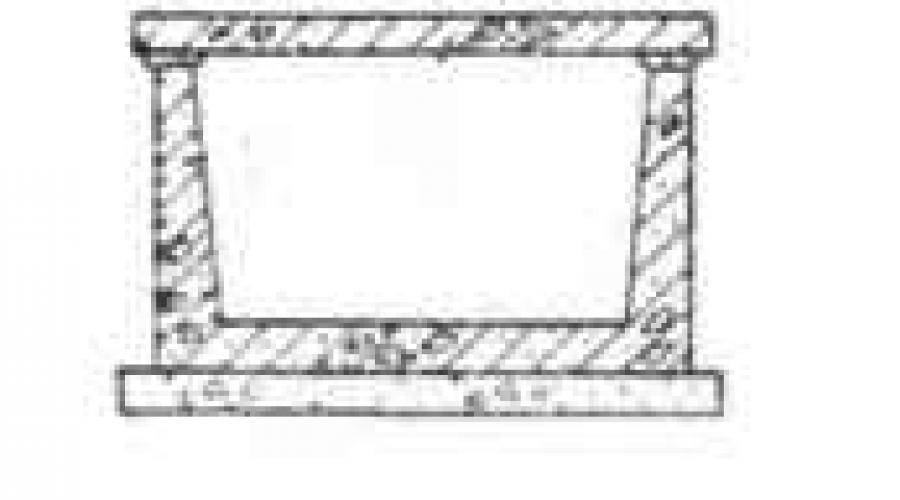
In KS-type channels, wall panels are installed in the grooves of the bottom slab and filled with concrete. These channels are covered with flat reinforced concrete slabs.
.jpg)
The bases of all types of canals are made of concrete slabs or sand preparation, depending on the type of soil.
Along with the channels discussed above, other types are also used.
Vaulted channels consist of reinforced concrete arches or semicircular shells that cover the pipeline. At the bottom of the trench, only the base of the channel is made.
For large-diameter pipelines, a vaulted two-cell channel with a dividing wall is used, while the channel arch is formed from two half-vaults.
When installing a non-passable channel intended for laying in wet and soft soils, the walls and bottom of the channel are made in the form of a reinforced concrete trough-shaped tray, and the ceiling consists of prefabricated reinforced concrete slabs. The outer surface of the tray (walls and bottom) is covered with waterproofing from two layers of roofing material on bitumen mastic, the surface of the base is also covered with waterproofing, then the tray is installed or concreted. Before filling the trench, the waterproofing is protected with a special wall made of brick.
Replacement of failed pipes or repair of thermal insulation in such channels is possible only by developing groups, and sometimes by dismantling the pavement. Therefore, the heating network in non-passable channels is routed along lawns or in green areas.
Semi-bore channels. IN difficult conditions When heating pipes cross existing underground devices (under the roadway, at a high level of groundwater), semi-passable channels are installed instead of impassable ones. Semi-through channels are also used for a small number of pipes in places where, due to operating conditions, opening of the roadway is excluded. The height of the semi-bore channel is taken equal to 1400 mm. The channels are made of prefabricated reinforced concrete elements. The designs of semi-through and through channels are almost similar.
Passage channels used when there are a large number of pipes. They are laid under the pavements of large highways, in the territories of large industrial enterprises, in areas adjacent to the buildings of thermal power plants. Along with heat pipelines, other underground communications are located in the passage channels - electrical cables, telephone cables, water supply, gas pipelines, etc. The collectors provide free access for service personnel to the pipelines for inspection and emergency response.
Passage channels must have natural ventilation with a threefold air exchange, ensuring an air temperature of no more than 40 ° C, and lighting. Entrances to passage channels are arranged every 200 - 300 m. In places where gland expansion joints designed to absorb thermal expansion, locking devices and other equipment are located, special niches and additional hatches are installed. The height of the passage channels must be at least 1800 mm.
Their designs are of three types − from ribbed slabs, from frame structure links and from blocks.
Passage channels made of ribbed slabs, perform from four reinforced concrete panels: bottom, two walls and floor slabs, manufactured in a factory manner on rolling mills. The panels are connected with bolts, and the outer surface of the channel overlap is covered with insulation. Channel sections are installed on a concrete slab. The weight of one section of such a channel with a cross-section of 1.46x1.87 m and a length of 3.2 m is 5 tons, entrances are arranged every 50 m.
Passage channel made of reinforced concrete frame sections, the top is covered with insulation. The channel elements have a length of 1.8 and 2.4 m and are of normal and increased strength when buried, respectively, up to 2 and 4 m above the ceiling. The reinforced concrete slab is placed only under the joints of the links.
The next view is collector made of reinforced concrete blocks three types: L-shaped wall, two floor slabs and bottom. The blocks at the joints are connected with monolithic reinforced concrete. These collectors are also made normal and reinforced.
Channelless installation.
When laying without channels, the protection of pipelines from mechanical influences is provided by reinforced thermal insulation- shell.
Advantages channelless installation pipelines are: a relatively low cost of construction and installation work, a reduction in the volume of excavation work and a reduction in construction time. To her shortcomings include: the complication of repair work and the difficulty of moving pipelines clamped by soil. Channelless pipeline laying is widely used in dry sandy soils. It is used in wet soils, but with a mandatory installation in the area where drainage pipes are located.
Movable supports are not used for channelless laying of pipelines. Pipes with thermal insulation are laid directly on a sand cushion located on the pre-leveled bottom of the trench. The sand cushion, which is a bed for pipes, has the best elastic properties and allows for the greatest uniformity of temperature movements. In the weak and clay soils the layer of sand at the bottom of the trench should be at least 100-150 mm thick. Fixed supports for ductless pipe laying are reinforced concrete walls installed perpendicular to the heating pipes.
Compensation for thermal movements of pipes for any method of their ductless installation is ensured using bent or stuffing box compensators installed in special niches or chambers.
At turns of the route, in order to avoid pinching pipes in the ground and ensure possible movements create impassable channels. In places where the pipeline intersects the wall of the drip, as a result of uneven settlement of the soil and the base of the channel, the greatest bending of the pipelines occurs. To avoid bending the pipe, it is necessary to leave a gap in the hole in the wall, filling it with elastic material (for example, asbestos cord). Thermal insulation of the pipe includes an insulating layer of autoclaved concrete with a volumetric weight of 400 kg/m3, having steel reinforcement, a waterproofing coating consisting of three layers of brizol on bitumen-rubber mastic, which includes 5-7% rubber crumbs and protective layer, made of asbestos-cement plaster on a steel mesh.
Return pipelines are insulated in the same way as supply lines. However, the presence of return line insulation depends on the diameter of the pipes. For pipe diameters up to 300 mm, insulation is required; with a pipe diameter of 300-500 mm, the insulation device must be determined by the technique using an economic calculation based on local conditions; for pipes with a diameter of 500 mm or more, insulation is not provided. Pipelines with such insulation are laid directly on the leveled compacted soil of the base of the trench.
To lower the groundwater level, special drainage pipelines are provided, which are laid at a depth of 400 mm from the bottom of the canal. Depending on the operating conditions, drainage devices can be made of various pipes: for non-pressure drainages, ceramic concrete and asbestos-cement are used, and for pressure drains, steel and cast iron are used.
Drainage pipes are laid with a slope of 0.002-0.003. At turns and when there are differences in pipe levels, special inspection wells according to the type of sewer.
Overhead laying of pipelines.
Based on the ease of installation and maintenance, laying pipes above the ground is more profitable than laying them underground. It also requires less material costs. However, this will spoil appearance environment and therefore this type of pipe laying cannot be used everywhere.
Load-bearing structures at overhead laying of pipelines serve: for small and medium diameters - overhead supports and masts, ensuring the location of pipes at the required distance from the surface; for pipelines of large diameters, as a rule, trestle supports. The supports are usually made of reinforced concrete blocks. Masts and overpasses can be either steel or reinforced concrete. The distance between supports and masts during overhead installation should be equal to the distance between supports in the channels and depends on the diameters of the pipelines. In order to reduce the number of masts, intermediate supports are arranged using guy wires.
When laying above ground, thermal elongations of pipelines are compensated using bent expansion joints, which require minimal maintenance time. Maintenance of fittings is carried out from specially arranged sites. Roller bearings should be used as moving ones, creating minimal horizontal forces.
Also, when laying pipelines above ground, low supports can be used, which can be made of metal or low concrete blocks. At the intersection of such a route with pedestrian paths install special bridges. And when crossing roads, either a compensator of the required height is installed or a channel is laid under the road for the passage of pipes.
Currently being used following types overhead gaskets:
On free-standing masts and supports (Fig. 4.1);
Rice. 4.1. Laying pipelines on free-standing masts
Fig. 4.2 - on overpasses with a continuous span in the form of trusses or beams (Fig. 4.2);

Rice. 4.2. Overpass with a span for laying pipelines
Fig. 4.3 - on rods attached to the tops of the masts (cable-stayed structure, Fig. 4.3);

Rice. 4.3. Laying pipes with suspension on rods (cable-stayed design)
On brackets.
Gaskets of the first type are the most rational for pipelines with a diameter of 500 mm or more. Pipelines of larger diameter can be used as load-bearing structures for laying or suspending several small-diameter pipelines that require more frequent installation of supports.
It is advisable to use overpass gaskets with a continuous flooring for passage only when there is a large number of pipes (at least 5 - 6 pieces), as well as when regular supervision of them is necessary. In terms of construction cost, a walk-through overpass is the most expensive and requires highest flow rate metal, since the trusses or beam deck are usually made of rolled steel.
The third type of installation with a suspended (cable-stayed) span structure is more economical, as it allows you to significantly increase the distances between masts and thereby reduce the consumption of building materials. The simplest structural forms of suspended gaskets are obtained with pipelines of equal or similar diameters.
When laying large and small diameter pipelines together, a slightly modified cable-stayed structure is used with purlins made of channels suspended on rods. Purlins allow installation of pipeline supports between masts. However, the possibility of laying pipelines on overpasses and suspended on rods in urban environments is limited and is applicable only in industrial areas. The greatest use has been made for laying water pipelines on free-standing masts and supports or on brackets. Masts and supports are usually made of reinforced concrete. Metal masts are used in exceptional cases for small volumes of work and reconstruction of existing heating networks.
Masts according to their purpose are divided into the following types:
§ for movable supports of pipelines (so-called intermediate);
§ for fixed pipeline supports (anchors), as well as those installed at the beginning and end of a section of the route;
§ tracks installed at turns;
§ used to support pipeline expansion joints.
Depending on the number, diameter and purpose of the pipelines being laid, the masts are made in three different structural forms: single-post, two-post and four-post spatial design.
When designing air spacers, one should strive to increase the distances between masts as much as possible.
However, for unhindered water flow when pipelines are turned off, the maximum deflection should not exceed
f = 0,25∙i∙l,
Where f- pipeline deflection in the middle of the span, mm; i - slope of the pipeline axis; l- distance between supports, mm.
Precast concrete mast structures are usually assembled from the following elements: posts (columns), crossbars and foundations. The dimensions of the prefabricated parts are determined by the number and diameter of the pipelines being laid.
When laying from one to three pipelines, depending on the diameter, single-post free-standing masts with consoles are used; they are also suitable for cable-stayed suspension of pipes on rods; then a top device is provided for attaching the rods.
Masts of a solid rectangular section are permissible if the maximum dimensions cross section do not exceed 600 x 400 mm. At large sizes to facilitate the design, it is recommended to provide cutouts along the neutral axis or use centrifuged ones as racks reinforced concrete pipes factory made.
For multi-pipe installations, intermediate support masts are most often designed as a two-post structure, single-tier or two-tier.
Prefabricated two-post masts consist of the following elements: two posts with one or two consoles, one or two crossbars and two glass-type foundations.
The masts on which the pipelines are fixedly fixed are subject to load from horizontally directed forces transmitted by the pipelines, which are laid at a height of 5 - 6 m from the ground surface. To increase stability, such masts are designed in the form of a four-post spatial structure, which consists of four posts and four or eight crossbars (with a two-tier arrangement of pipelines). The masts are installed on four separate glass-type foundations.
When laying large-diameter pipelines above ground, the load-bearing capacity of the pipes is used, and therefore no span structure is required between the masts. Suspension of large-diameter pipelines on rods should not be used, since such a design will practically not work.
Fig.4.4As an example, the laying of pipelines on reinforced concrete masts is shown (Fig. 4.4).
Two pipelines (direct and return) with a diameter of 1200 mm are laid on roller supports on reinforced concrete masts installed every 20 m. The height of the masts from the ground surface is 5.5 - 6 m. Prefabricated reinforced concrete masts consist of two foundations connected to each other by a monolithic joint, two columns of rectangular section 400 x 600 mm and a crossbar.

Rice. 4.4. Laying pipelines on reinforced concrete masts:
1 - column; 2 - crossbar; 3 - communication; 4 - foundation; 5 - connecting joint; 6 - concrete preparation.
The columns are interconnected by metal diagonal ties made of angle steel. The connection of the ties with the columns is made with gussets welded to the embedded parts, which are embedded in the columns. The crossbar, which serves as a support for pipelines, is made in the form of a rectangular beam with a cross-section of 600 x 370 mm and is attached to the columns by welding embedded steel sheets.
The mast is designed for the weight of the pipe span, horizontal axial and lateral forces arising from the friction of pipelines on the roller supports, as well as for wind load.

Rice. 4.5. Fixed support:
1 - column; 2 - transverse crossbar; 3 - longitudinal crossbar; 4 - cross connection; 5 - longitudinal connection; 6 - foundation
The fixed support (Fig. 4.5), designed for a horizontal force from two pipes of 300 kN, is made of prefabricated reinforced concrete parts: four columns, two longitudinal crossbars, one transverse support crossbar and four foundations connected in pairs.
In the longitudinal and transverse directions, the columns are connected by metal diagonal braces made of angle steel. The pipelines are secured to the supports with clamps covering the pipes and gussets at the bottom of the pipes, which rest against a metal frame made of channels. This frame is attached to reinforced concrete crossbars by welding to the embedded parts.
Laying pipelines on low supports has found wide application in the construction of heating networks in unplanned areas of new urban development areas. It is more expedient to cross rough or swampy terrain, as well as small rivers, in this way using the bearing capacity of pipes.
However, when designing heating networks with the laying of pipelines on low supports, it is necessary to take into account the period of planned development of the territory occupied by the route for urban development. If in 10 - 15 years it will be necessary to enclose pipelines in underground channels or reconstruct the heating network, then the use of air laying is inappropriate. To justify the use of the method of laying pipelines on low supports, technical and economic calculations must be performed.
When laying large-diameter pipelines above ground (800-1400 mm), it is advisable to lay them on separate masts and supports using special prefabricated reinforced concrete structures of factory production that meet the specific hydrogeological conditions of the heating main route.
Design experience shows the cost-effectiveness of using pile foundations for the foundations of both anchor and intermediate masts and low supports.
Aboveground heating mains of large diameter (1200-1400 mm) of considerable length (5 - 10 km) are built according to individual designs using high and low supports on a pile foundation.
We have experience in constructing heating mains with pipe diameters D= 1000 mm from the thermal power plant using rack piles in the wetlands of the route, where rocky soils lie at a depth of 4-6 m.
Calculation of supports on a pile foundation on joint action vertical and horizontal loads are carried out in accordance with SNiP II-17-77 “Pile foundations”.
When designing low and high supports for laying pipelines, the designs of standardized prefabricated reinforced concrete free-standing supports designed for process pipelines can be used [3].
The design of low supports of the type of “swinging” foundations, consisting of a reinforced concrete vertical shield installed on a flat foundation slab, was developed by AtomTEP. These supports can be used in various soil conditions (with the exception of heavily watered and subsiding soils).
One of the most common types of aerial laying of pipelines is the installation of the latter on brackets fixed in the walls of buildings. The use of this method can be recommended when laying heating networks on the territory of industrial enterprises.
When designing pipelines located on the outer or inner surface of walls, you should choose such a placement of pipes so that they do not cover window openings, did not interfere with the placement of other pipelines, equipment, etc. The most important thing is to ensure that the brackets are securely fastened to the walls of existing buildings. Designing the installation of pipelines along the walls of existing buildings should include an examination of the walls in situ and a study of the designs for which they were built. In case of significant loads transmitted by pipelines to the brackets, it is necessary to calculate the overall stability of the building structures.
The pipelines are laid on brackets with welded sliding support bodies. The use of roller movable supports for external laying pipelines are not recommended due to the difficulty of periodically lubricating and cleaning them during operation (without which they will work as sliding ones).
In case of insufficient reliability of the walls of the building, constructive measures must be taken to disperse the forces transmitted by the brackets by reducing spans, installing struts, vertical racks etc. Brackets installed in places where fixed pipeline supports are installed must be designed to withstand the forces acting on them. Usually they require additional fastening by installing struts in horizontal and vertical planes. In Fig. 4.6 shows a typical design of brackets for laying one or two pipelines with a diameter of 50 to 300 mm.

Rice. 4.6. Laying pipelines on brackets.
Channel gasket satisfies most requirements, but its cost, depending on the diameter, is 10-50% higher than channelless. Channels protect pipelines from the effects of ground, atmospheric and flood waters. The pipelines in them are laid on movable and fixed supports, while ensuring organized thermal elongation.
The technological dimensions of the channel are taken based on the minimum clear distance between the pipes and structural elements, which, depending on the diameter of the pipes 25-1400 mm, is respectively taken equal to: to the wall 70-120 mm; to overlap 50-100 mm; to the insulation surface of the adjacent pipeline 100-250 mm. Channel depth
accepted on the basis of the minimum volume of excavation work and the uniform distribution of concentrated loads from vehicles on the floor. In most cases, the thickness of the soil layer above the ceiling is 0.8-1.2 m, but not less than 0.5 m.
At centralized heating For laying heating networks, non-through, semi-through or through channels are used. If the laying depth exceeds 3 m, then semi-through or through channels are constructed to make it possible to replace pipes.
Impassable channels used for laying pipelines with a diameter of up to 700 mm, regardless of the number of pipes. The design of the channel depends on the soil moisture. In dry soils, block channels with concrete or brick walls, or reinforced concrete single- and multi-cell ones are more often installed. In soft soils, first a concrete base is made, on which a reinforced concrete slab is installed. When the groundwater level is high, a drainage pipeline is laid at the base of the canal to drain it. If possible, the heating network in non-passable channels is placed along the lawns.
Currently, channels are mainly constructed from prefabricated reinforced concrete tray elements (regardless of the diameter of the pipelines being laid) of types KL, KLS, or wall panels types KS, etc. The channels are covered with flat reinforced concrete slabs. The bases of all types of channels are made of concrete slabs, lean concrete or sand preparation.
If it is necessary to replace failed pipes, or when repairing a heating network in non-passable channels, it is necessary to tear up the soil and dismantle the channel. In some cases, this is accompanied by opening of the bridge or asphalt surface.
Semi-bore channels. In difficult conditions when pipelines of the heating network cross existing underground communications, under the roadway, and at a high level of groundwater, semi-passable channels are installed instead of impassable ones. They are also used when laying large number pipes in places where, due to operating conditions, opening of the roadway is excluded, as well as when laying pipelines of large diameters (800-1400 mm). The height of the semi-bore channel is taken to be at least 1400 mm. The channels are made of prefabricated reinforced concrete elements - bottom slabs, wall block and floor slabs.
Passage channels. Otherwise they are called collectors; they are constructed in the presence of a large number of pipelines. They are located under the pavements of large highways, on the territory of large industrial enterprises, in areas adjacent to the buildings of thermal power plants. Together with heat pipelines, other underground communications are also placed in these channels: electrical and telephone cables, water supply, gas pipelines low pressure etc. For inspection and repair in collectors, free access of maintenance personnel to pipelines and equipment is ensured.
Collectors are made of reinforced concrete ribbed slabs, frame structure links, large blocks and volumetric elements. They are equipped with lighting and natural supply and exhaust ventilation with triple air exchange, ensuring an air temperature of no more than 30°C, and a device for removing water. Entrances to the collectors are provided every 100-300 m. For installation of compensating and locking devices Special niches and additional manholes must be made on the heating network.
Channelless installation. To protect pipelines from mechanical influences with this installation method, reinforced thermal insulation - a shell - is installed. The advantages of ductless installation of heat pipelines are the relatively low cost of construction and installation work, a small amount of excavation work and a reduction in construction time. Its disadvantages include the increased susceptibility of steel pipes to external soil, chemical and electrochemical corrosion.
With this type of gasket, movable supports are not used; pipes with thermal insulation are laid directly on a sand cushion poured onto the pre-leveled bottom of the trench. Fixed supports for ductless pipe laying, as well as for channel pipes, are reinforced concrete shield walls installed perpendicular to the heat pipes. For small diameter heat pipes, these supports are usually used outside the chambers or in chambers with a large diameter under large axial forces. To compensate for thermal elongation of pipes, bent or stuffing box expansion joints are used, located in special niches or chambers. At the turns of the route, in order to avoid pinching the pipes in the ground and to ensure their possible movement, impassable channels are constructed.
For channelless installation, backfill, prefabricated and monolithic types of insulation are used. Monolithic shells made of autoclaved reinforced foam concrete have become widespread.
Overhead laying. This type of gasket is the most convenient to operate and repair and is characterized by minimal heat losses and ease of detection of accident sites. Supporting structures for pipes are free-standing supports or masts that ensure the pipes are located at the required distance from the ground. For low supports, the clear distance (between the insulation surface and the ground) for a group of pipes up to 1.5 m wide is taken to be 0.35 m and at least 0.5 m for larger widths. Supports are usually made of reinforced concrete blocks, masts and overpasses are made of steel and reinforced concrete. The distance between supports or masts when laying pipes with a diameter of 25-800 mm above ground is taken to be 2-20 m. Sometimes one or two intermediate suspended supports are installed using guy wires in order to reduce the number of masts and reduce capital investments in the heating network.
To service fittings and other equipment installed on the pipelines of the heating network, special platforms with fences and ladders are arranged: stationary at a height of 2.5 m or more and mobile at a lower height. In places where main valves, drainage, drainage and air devices are installed, insulated boxes are provided, as well as devices for lifting people and fittings.
5.2. Drainage of heating networks
When laying heat pipes underground, in order to avoid water penetration into the thermal insulation, an artificial lowering of the groundwater level is provided. For this purpose, together with the heat pipes, drainage pipelines are laid 200 mm below the base of the channel. The drainage device consists of a drainage pipe and a filtration material of sand and gravel. Depending on the operating conditions, various drainage pipes are used: for non-pressure drainage - socketed ceramic, concrete and asbestos-cement, for pressure drainage - steel and cast iron with a diameter of at least 150 mm.
At turns and when there are differences in pipe laying, inspection wells are installed like sewer wells. In straight sections, such wells are provided at least 50 m apart. If drainage of drainage water into reservoirs, ravines or sewers by gravity is not possible, pumping stations are built, which are placed near the wells at a depth depending on the elevation of the drainage pipes. Pumping stations are usually built from reinforced concrete rings with a diameter of 3 m. The station has two compartments - a machine room and a reservoir for receiving drainage water.
5.3. Structures on heating networks
Heating chambers are intended for servicing equipment installed on heating networks with underground installation. The dimensions of the chamber are determined by the diameter of the heating network pipelines and the dimensions of the equipment. Shut-off valves, stuffing box and drainage devices, etc. are installed in the chambers. The width of the passages is at least 600 mm, and the height is at least 2 m.
Heating chambers are complex and expensive underground structures, therefore they are provided only in places where shut-off valves and stuffing box compensators are installed. Minimum distance from the ground surface to the top of the chamber ceiling is taken equal to 300 mm.
Currently, heating chambers made of precast concrete. In some places, the chambers are made of brick or monolithic reinforced concrete.
On heat pipelines with a diameter of 500 mm and above, electrically driven valves with a high spindle are used, so an above-ground pavilion about 3 m high is built above the recessed part of the chamber.
Supports. To ensure organized joint movement of the pipe and insulation during thermal expansion, movable and fixed supports are used.
Fixed supports, intended for securing pipelines of heating networks at characteristic points, they are used for all installation methods. Characteristic points on the route of the heating network are considered to be the places of branches, the installation sites of valves, stuffing box compensators, mud traps and the installation sites of fixed supports. The most widespread are panel supports, which are used both for ductless installation and for laying heating network pipelines in non-passable channels.
The distances between fixed supports are usually determined by calculating the strength of pipes at a fixed support and depending on the magnitude of the compensating capacity of the adopted compensators.
Movable supports installed for ducted and ductless installation of heating network pipelines. There are the following types of different designs of movable supports: sliding, roller and suspended. Sliding supports are used for all laying methods, except channelless. Rollers are used for overhead laying along the walls of buildings, as well as in collectors and on brackets. Suspended supports are installed when laying above ground. In places where there is possible vertical movement of the pipeline, spring supports are used.
The distance between the movable supports is taken based on the deflection of the pipelines, which depends on the diameter and wall thickness of the pipes: the smaller the pipe diameter, the smaller the distance between the supports. When laying pipelines with a diameter of 25-900 mm in channels, the distance between movable supports is taken to be 1.7-15 m. When laying above ground, where a slightly larger deflection of pipes is allowed, the distance between supports for the same pipe diameters is increased to 2-20 m.
Compensators used to relieve temperature stresses that arise in pipelines during elongation. They can be flexible U-shaped or omega-shaped, hinged or stuffing box (axial). In addition, pipeline turns at an angle of 90-120° available on the route are used, which work as compensators (self-compensation). Installation of expansion joints involves additional capital and operating costs. Minimum costs are obtained in the presence of self-compensation areas and the use of flexible compensators. When developing heating network projects, a minimum number of axial expansion joints, making maximum use of natural compensation of heat conductors. The choice of compensator type is determined by the specific conditions for laying pipelines of heating networks, their diameter and coolant parameters.
Anti-corrosion coating of pipelines. To protect heat pipelines from external corrosion caused by electrochemical and chemical processes under the influence of the environment, anti-corrosion coatings are used. Factory-made coatings are of high quality. The type of anti-corrosion coating depends on the temperature of the coolant: bitumen primer, several layers of insulation over insulating mastic, wrapping paper or putty and epoxy enamel.
Thermal insulation. For thermal insulation of pipelines of heating networks, various materials are used: mineral wool, foam concrete, reinforced foam concrete, aerated concrete, perlite, asbestos cement, sovelite, expanded clay concrete, etc. For duct installation, suspended insulation made of mineral wool is widely used, for non-channel installation - from autoclaved reinforced foam concrete, asphalt -toizol, bitumen perlite and foam glass, and sometimes backfill insulation.
Thermal insulation usually consists of three layers: thermal insulation, cover and finishing. The covering layer is designed to protect the insulation from mechanical damage and moisture, i.e. to preserve thermal properties. To construct the covering layer, materials are used that have the necessary strength and moisture permeability: roofing felt, glassine, fiberglass, foil insulation, sheet steel and duralumin.
Reinforced waterproofing and asbestos-cement plaster over a wire mesh frame are used as a covering layer for ductless installation of heat pipes in moderately moist sandy soils; for channel installation - asbestos-cement plaster over a wire mesh frame; for above-ground installation - asbestos-cement half-cylinders, sheet steel casing, galvanized or painted aluminum paint.
Suspended insulation is a cylindrical shell on the surface of the pipe, made of mineral wool, molded products (slabs, shells and segments) and autoclaved foam concrete.
The thickness of the thermal insulation layer is taken according to calculation. The maximum coolant temperature is taken as the calculated coolant temperature if it does not change during the operating period of the network (for example, in steam and condensate networks and hot water supply pipes), and the average for the year if the coolant temperature changes (for example, in water networks). The ambient temperature in the collectors is taken to be +40°C, the soil on the pipe axis is the average for the year, the outside air temperature for above-ground installation is the average for the year. In accordance with the design standards for heating networks, the maximum thickness of thermal insulation is taken based on the installation method:
For overhead installation and in collectors with pipe diameter 25-1400
mm insulation thickness 70-200 mm;
In channels for steam networks - 70-200 mm;
For water networks - 60-120 mm.
fittings, flange connections and other shaped parts of heating networks, as well as pipelines, are covered with a layer of insulation with a thickness equal to 80% of the thickness of the pipe insulation.
When laying heat pipes without ducts in soils with increased corrosive activity, there is a danger of pipe corrosion from stray currents. To protect against electrical corrosion, measures are taken to prevent the penetration of stray currents into metal pipes, or so-called electrical drainage or cathodic protection (cathodic protection stations) are installed.
Factory information technologies"LIT" in Pereslavl-Zalessky produces flexible thermal insulation products from foamed polyethylene with a closed pore structure "Energoflex". They are environmentally friendly, as they are manufactured without the use of chlorofluorocarbons (freon). During operation and during processing, the material does not release into the environment toxic substances and does not have harmful effects on the human body upon direct contact. Working with it does not require special tools and increased security measures.
"Energoflex" is intended for thermal insulation of engineering communications with a coolant temperature from minus 40 to plus 100 ° C.
Energoflex products are produced in the following forms:
Tubes in 73 standard sizes with internal diameters from 6 to 160 mm and
wall thickness from 6 to 20 mm;
Rolls are 1 m wide and 10, 13 and 20 mm thick.
The thermal conductivity coefficient of the material at 0°C is 0.032 W/(m-°C).
Mineral wool thermal insulation products are produced by the enterprises of Termosteps JSC (Tver, Omsk, Perm, Samara, Salavat, Yaroslavl), AKSI (Chelyabinsk), Tizol JSC, Nazarovsky ZTI, Komat plant (Rostov -on-Don), CJSC "Mineral Wool" (Zheleznodorozhny, Moscow region), etc.
Imported materials from ROCKWOLL, Ragos, Izomat and others are also used.
Performance properties fibrous thermal insulation materials depend on the composition of the raw materials used by various manufacturers and technological equipment and vary over a fairly wide range.
Technical thermal insulation made of mineral wool is divided into two types: high-temperature and low-temperature. The company JSC "Mineral Wool" produces thermal insulation "ROCKWOLL" in the form of fiberglass mineral wool boards and mats. More than 27% of all fibrous thermal insulation materials produced in Russia are URSA thermal insulation produced by JSC Flyderer-Chudovo. These products are made from staple glass fiber and are characterized by high thermal and acoustic characteristics. Depending on the brand of the product, the thermal conductivity coefficient
such insulation ranges from 0.035 to 0.041 W/(m-°C), at a temperature of 10°C. The products are characterized by high environmental performance; they can be used if the coolant temperature is in the range from minus 60 to plus 180°C.
CJSC "Isolation Plant" (St. Petersburg) produces insulated pipes for heating networks. Reinforced foam concrete is used as insulation here, the advantages of which include:
High maximum application temperature (up to 300°C);
High compressive strength (not less than 0.5 MPa);
Can be used for channelless installation on any depth
without laying heat pipelines and in all soil conditions;
The presence of a passivating protective layer on the insulated surface
film that occurs when foam concrete comes into contact with the metal of the pipe;
The insulation is non-flammable, which allows it to be used in all
types of installation (overground, underground, channel or non-channel).
The thermal conductivity coefficient of such insulation is 0.05-0.06 W/(m-°C).
One of the most promising methods today is the use of pre-insulated ductless pipelines with polyurethane foam (PPU) insulation in a polyethylene sheath. The use of “pipe-in-pipe” type pipelines is the most progressive way of energy saving in the construction of heating networks. In the USA and Western Europe, especially in northern regions, these designs have been used since the mid-60s. In Russia - only since the 90s.
The main advantages of such designs:
Increasing the durability of structures up to 25-30 years or more, i.e.
2-3 times;
Reduction of heat losses by up to 2-3% compared to existing ones
20^40% (or more) depending on the region;
Reducing operating costs by 9-10 times;
Reducing the cost of repairing heating mains by at least 3 times;
Reducing capital costs during the construction of new heating mains in
1.2-1.3 times and a significant (2-3 times) reduction in construction time;
Significant increase in the reliability of heating mains constructed according to
new technology;
Possibility of using an operational remote control system
control of insulation moisture, which allows timely response
to violate the integrity steel pipe or polyethylene guide
insulation coating and prevent leaks and accidents in advance.
On the initiative of the Moscow Government, Gosstroy of Russia, RAO UES of Russia, CJSC MosFlowline, TVEL Corporation (St. Petersburg) and a number of other organizations, the Association of Manufacturers and Consumers of Pipelines with Industrial Polymer Insulation was created in 1999.
CHAPTER 6. CRITERIA FOR SELECTION OF THE OPTIMAL OPTION
§ 2. Methods of underground, above-ground and above-ground laying and their technical and economic indicators
The installation of sanitary and technical communications in areas of permafrost can cause the soil to thaw due to the heat generated by the pipelines. As a result, the stability of both the pipelines themselves and buildings may be compromised. Methods for laying sanitary and technical communications must be linked to the methods of construction of buildings and structures and depend on the properties of the foundation soils and other factors, the most important of which is the location of the network route in relation to the built-up area and its architectural and planning solution.
Exist the following types laying of sanitary and technical communications: underground, above-ground and above-ground. These types of gaskets, in turn, can be single or combined.
Ground and overhead laying Due to the absence of contact of pipes with the ground and limited heat release into the soil, the foundations disturb to the least extent the natural thermal regime of permafrost soils. Such gaskets clutter the territory of populated areas, complicate the construction of passages, the organization of snow protection and snow removal.
Underground laying It is advisable to carry out within the boundaries of the settlement in order to achieve maximum improvement of the territory. Water supply and sewer networks can be laid directly in the ground, and heating networks and steam pipelines can be laid in special channels. If there are such channels, it is advisable to lay water supply, sewerage and electrical cables in them.
The underground installation of heating networks is very expensive and requires special measures to maintain the thermal regime of permafrost soils at the base of the networks. So, for example, the cost 1 linear m channel for district heating in the conditions of Norilsk averages 300 rubles. The cost of a two-tier channel for the combined installation of a heating network, water supply, sewerage and electrical cables under the same conditions averages about 450 rubles. behind 1 linear m. Therefore, underground installation of heating networks is advisable only in compact buildings with multi-story (4-5 floors) buildings and in conjunction with other communications.
If the development is carried out with two- and three-story buildings with gaps, then the underground installation of heating networks usually turns out to be economically infeasible. In such cases, above-ground laying is most often used along the facades and attics of buildings, and between buildings - along overpasses, fences and fences. In this case, water supply and sewerage can be laid in the ground without channels. If the soils of the base of the pipes are subsidence, then to ensure their stability it is necessary to replace the soils with non-subsidence ones to a depth determined by thermal engineering calculations.
For small villages, if it is possible to route the network within blocks without crossing streets or with a minimum number of intersections, the most economical option is to lay heating networks above ground in ring insulation or in insulated ducts together with a water supply system. In this case, the sewerage system must be laid in the ground without channels.
In soils that subsidence during thawing, especially in soils that transform during thawing into a fluid-plastic or fluid state, when laying underground pipelines, an artificial foundation is necessary. The cost of such a foundation is directly dependent on the depth of thawing of the soil under the pipes.
When laying pipelines in soils that do not settle and do not lose their bearing capacity when thawed, the decisive condition is to protect them from freezing by reducing heat loss. In this case, the depth of placement is increased to 1.5-2.0 m; greater depth is undesirable, as it makes it difficult to detect pipeline failure sites and repair them, both in summer and especially in winter.
In order to reduce heat loss and the size of the taliks under the pipes, underground laying of water supply and sewerage systems is used in thermal insulation: in boxes made of wood or reinforced concrete filled with sawdust or mineral wool, in a ring box made of foam concrete, mineral wool, felt impregnated with resin. All these types of thermal insulation fail to achieve their goal when humidified. insulating material. Local faults in waterproofing (and therefore thermal insulation) lead to thawing of the base and uneven settlement of pipelines, which is the most undesirable. Restoring thermal and waterproofing during repairs is a complex and labor-intensive process. The use of boxes creates additional difficulties in detecting and eliminating leaks. Any leak entails a violation of thermal insulation. The cost of thermal insulation usually exceeds the cost of an artificial foundation for water supply and sewerage. Therefore, the widespread use of thermal insulation for water supply and sewer pipelines when laying them in the ground is impractical.
Let's consider some designs of pipeline foundations laid in the ground.
Soil foundation(Figure IV-1). Ice-saturated local soils at the base of the fuel pipeline are replaced by non-subsidence soils with a low filtration coefficient to the calculated thawing depth. Sandy, gravel-sandy soils in some cases are compacted by preliminary thawing. For replacement, light sandy loams and fine-grained silty sands in a thawed state are used; in this case, an admixture of pebbles, gravel, crushed stone up to 40.....-45% or local dehydrated and compacted soil is desirable. A waterproofing layer of adobe concrete or clay with a thickness of 25-30 cm.
The width of the artificial foundation is assumed to be equal to the width of the trench, and the height is determined by calculation.
In the absence of a leak, the radius of thawing from heat releases from water supply or sewer pipelines on average does not exceed 1.2 m. If we take into account the increased intensity of thawing of soils that replace ice-saturated soils, then the depth of replacement will not exceed 1.5 m. It must be assumed that in many cases the soil foundation will be economically beneficial and technically feasible.
Flat base It is used to reduce the unevenness of subsidence during thawing of subsidence soils and is made in the form of longitudinal logs in two logs. To prevent the tracks from warping during subsidence, as a result of which the pipeline is destroyed, they must be securely fastened.
Floating base used in ice-saturated soils and is a continuous flooring of plates laid across the trench; This type of foundation is quite reliable, but cannot be widely recommended due to the high cost and consumption of a large amount of timber.
>
Rice. IV-2. Pipeline on a pile foundation. 1 - pipeline; 2 - log (timber) ∅30 cm on dowels (staggered joints); 3 - piles ∅30 cm through 3m with recess on 3m below the active layer; 4 - gaskets through 10 cm; 5 - backfilling with local soil
Pile foundation(Fig. IV-2) is used in highly subsidence soils. Driving piles into permafrost soil requires labor-intensive and expensive work on steaming the soil or drilling wells. Piles have to be placed frequently, because in pipes that carry a large load from the soil, significant bending moments occur on the supports. Such grounds are characterized high cost.

Underground overpasses(Fig. IV-3) due to their high cost, they are used in exceptional cases, for example, for sewerage in subsidence soils that thaw to great depths, when the route passes near a building with large heat releases, built according to methods I or IV and located higher in the relief.
The issue of using one or another type of basis is resolved by comparing technical and economic indicators.
To eliminate the possibility of intense movement of supra-permafrost water flow along underground pipelines Clay concrete lintels are used across the trenches. The lintels cut into the frozen base and walls of the trenches on 0.6-1.0 m. The distance between the lintels is determined depending on the longitudinal slope so that the pressure at the lintel does not exceed 0.4-0.5 m; Typically this distance ranges from 50 to 200 m.
In pebble, gravel and other well-filtering soils, the installation of dams is not advisable, since the flow of supra-permafrost water easily bypasses them.
Laying in earthen beads
>
Rice. IV-4. Laying pipes in earthen beads. 1 - pipeline; 2 - thick clay concrete layer 20 cm; 3 - local soil; 4 - sand and gravel layer; 5 - local dewatered and compacted soil
This installation method (Fig. IV-4) is used under fairly favorable permafrost-soil conditions, in the absence of thermal insulation materials on site, and the pipeline route must pass through an undeveloped area. This type of gasket has several advantages:
- there is no need to carry out labor-intensive earthworks of digging trenches;
- pipe leaks are easier to detect and fix;
- filtering of supra-permafrost water along the pipes is eliminated;
- the presence of a talik around the pipes allows longer interruptions in the movement of water through them than with ground and above-ground installations;
- there is no need for thermal and waterproofing of pipes.
Main disadvantages this method is excessive cluttering of the territory and the complexity of crossings. In addition, this creates conditions for greater snow cover in the area.
Underground laying of pipelines in channels
Laying pipelines in underground channels is a relatively expensive type of network construction; nevertheless, in a number of cases, channel laying is advisable, if we take into account not only one-time capital investments, but also operating costs. The feasibility of combined laying of communications in underground channels in comparison with a single underground one should be confirmed by the cost of construction attributed to 1 m2 living space, and operational reliability utility networks. Combined laying is usually justified in unfavorable climatic and frozen soil conditions.
Channels can be pass-through (semi-pass-through) and non-pass-through, single-tier and two-tier. In two-tier channels, the lower tier of which is passable, the upper tier can be either semi-passable or non-passable. Channel design with semi-bore top tier bulky and high cost. The single-tier channel design is the most economical and convenient to use.
In the case of installing different types of channels in a populated area (which must be justified), it is necessary, based on the conditions of industrialization of construction, to achieve a minimum number of standard sizes of elements.

Impassable up to 0.9 m channels (Fig. IV-5) can be used in short sections (house outlets and inlets, road intersections, etc.) while ensuring stability conditions and operating requirements. Non-passable channels should be constructed with minimal penetration into the ground (no more than 0.5-0.7 m from the floor to the ground surface). They must have a removable cover for cleaning channels, inspecting and repairing pipelines. The longitudinal slope of non-passable channels to ensure water drainage along the bottom must be at least 0.007.

Passage channels with a height of at least 1.8 m(Fig. IV-6) must have dimensions that provide free passage through them for inspection and repair of pipes, fittings and electrical cables.
>
Rice. IV-7. Reinforced concrete two-tier passage channel. 1 - sewerage; 2 - heating network: 3 - water supply; 4 - shelves for electrical and communication cables; 5 - sand, δ = 10 cm; 6 - clay concrete, δ = 20 cm; 7 - replaced soil (calculated thickness)
With significant depths of channels and large heat releases of communications, taliks formed under the channels can reach significant size. In such cases, to reduce the penetration of heat into the base, based on a technical and economic comparison with other options, the feasibility of installing two-tier channels is revealed (Fig. IV-7). In the lower passage tier of such a channel, a sewer pipeline and electrical cables are placed, in the upper - non-passable or semi-passable - heating network and water supply pipes are laid.
When laying a combined sewer and water supply system, water valves must be placed in special chambers or sections isolated from the sewer pipeline.
In order to prevent destruction of both the canals themselves and nearby buildings and structures from thawing of the soil at the base, it is necessary:
- thermally insulate pipelines, minimizing their heat generation as much as possible;
- ventilate the channels in winter to remove heat so that the soils at their base that have thawed over the summer are completely frozen;
- arrange waterproofing along the bottom of the canal, preventing water from penetrating into the foundation soils. The foundations under the canals should be made of non-subsidence or low-subsidence soils.
In addition to replacing subsidence soils, it is possible to use preliminary thawing and compaction of foundation soils. Channels must be made of reinforced concrete, reinforced cement or other effective material. The construction of channels made of wood or concrete may be allowed with special justification, since concrete channels roads and do not meet the strength requirements for uneven settlement of the base, and wooden ones are susceptible to rotting, require extensive waterproofing work, and become silted with tiny soil particles; If they have sewerage, they create unsanitary conditions for the water supply.

Ventilation of channels is arranged natural and artificial (forced). Natural is carried out by device ventilation holes along the top of the channel at a distance 20-25 m depending on the dimensions of the channel and communications laid in it (Fig. IV-8). The efficiency of natural ventilation can be increased by installing exhaust shafts in buildings located near the canal; in this case, the distance between the holes on the channel for air flow can be increased to 100-150 m.
Discharge of emergency or waste water from the canal should be carried out from its end part, using a longitudinal slope, or from intermediate water collectors (waterproof pits) by pumping water out with pumps.
Heat and steam pipelines placed in channels should be moved as far as possible from the bottom of the channel; they must be in ring thermal insulation (for example, foam concrete with asbestos-cement plaster and waterproofing). The use of plastics with increased heat and waterproofing properties (foam plastic, polyethylene, etc.) for these purposes has great prospects.
The technical and economic feasibility of laying sewer networks in canals together with networks for various purposes in comparison with a single underground laying is revealed based on a comparison of the cost of construction and operation, attributed to 1 m2 living space, as well as assessing the stability of networks, their durability and thermal impact on nearby buildings and structures.
Ground laying of pipelines
TO ground type Gaskets usually refer to pipelines laid on low supports. In this case, between the pipe and the ground surface there must be a ventilated space of at least 30 cm, which is necessary to reduce heat release into the foundation soils and prevent snow drifts.
Ground laying of pipelines should be used outside the built-up areas of populated areas (as it is the cheapest), in low-lying and swampy sections of the route, in places with heavily ice-saturated permafrost soils.
In the built-up area, ground installation is allowed if there are a small number of pipeline intersections with driveways and sidewalks. Pipelines are thermally and waterproofed. The use of combustible materials both for the manufacture of ducts and heat-insulating backfills for steam pipelines and heating networks at a coolant temperature of 90 °C and above is not recommended by fire regulations. Slag backfill should also not be widely used due to possible destruction metal pipes corrosion when the slag is moistened.
Wooden boxes, being in conditions of variable humidity, are deformed, the filling is blown out, spills out and is easily moistened. Waterproofing of boxes roll materials does not achieve the goal because roll coverings are easily damaged. Therefore, boxes made of reinforced concrete are more reliable, but their cost with backfill is higher than the cost of ring heat and waterproofing of pipes.
In the case of combined installation, mainly for ease of use, thermal insulation is carried out independently for pipelines for various purposes.
The base for above-ground pipelines can be bulk sand-gravel or any other non-subsidence or low-subsidence soil, laid without disturbing the natural moss and vegetation cover during the work. In the case of subsidence soils of the natural foundation, it is necessary to replace them with non-subsidence ones to a depth determined by calculation.
Special supports are installed on an artificial soil foundation under the pipelines.
Leg supports of the transverse beams have a small height, as a result of which, when the supports settle, the thermal insulation of the pipes falls on the ground, easily becomes moistened and deteriorates. The installation of common supports for several pipelines is not recommended, since with uneven load the tracks give uneven settlement.

Town supports(Fig. IV-9) are a more advanced type of wooden supports; they make it easy to straighten the profile of pipelines in the event of small subsidence of the foundation by wedging the elements of the towns.

Reinforced concrete intermediate supports sliding and roller type (Fig. IV-10) are more economical and durable than wooden ones. Their disadvantage is the difficulty of straightening pipelines when embankments settle; To level the base, the pipeline must be lifted and the supports removed.

Fixed(anchor) supports(Fig. IV-11) are made of wood, concrete and reinforced concrete. With wooden supports, the pipes are secured to the support beams with bolts or pins.
Frame fixed supports require large volumes of work to develop and excavate soil from pits. Therefore, they can be recommended in cases where the use of pile supports is impractical (active layer of high thickness, high-temperature frozen soils characterized by low freezing forces, boulder crushed soils, etc.).
Massive concrete supports are arranged for pipelines of large diameters and during the construction of pipelines in 2 stages. For fastening metal parts, nests are left in the concrete mass, which must be filled with concrete of the lowest grades until the construction of the second stage pipeline. Otherwise, water accumulates in them, which, when frozen, can tear the concrete mass. To avoid thawing of the foundation soil due to exotherm during concrete hardening, as well as from heat flow through the support body, a sand cushion of thickness is laid on the bottom of the pit 20-30 cm.
In general, ground laying in the conditions of the Far North is the most economical type of laying sanitary and technical communications (excluding sewerage).
Aboveground pipeline laying

Aboveground laying of pipelines is carried out on overpasses, on pile supports rising above the terrain (Fig. IV-12), along the walls of buildings, attics and fences. The above-ground type of pipeline laying is used when crossing roads, hollows, ravines and streams, in factory areas, and in places with heavily ice-saturated permafrost soils.
Similar to above-ground installation, pipes are laid in ring thermal insulation or in insulated boxes.
Overpasses can be made of wood, reinforced concrete and metal. Metal overpasses used in flammable places. The production of reinforced concrete overpasses is difficult and their cost is high. Therefore, pile and frame wooden trestles are mainly used.
Advantages of above-ground installation:
- pipes and ducts do not cause snow deposits and do not interfere with snow removal;
- the issue of intersections with driveways and walkways is successfully resolved;
- pipes and their insulation are not exposed mechanical damage from transport and pedestrians;
- pipelines are not subject to snow drifts and are easily accessible for inspection and repair.
Disadvantages of above-ground installation:
- high cost compared to land installation;
- inconvenience of installing fittings, especially fire hydrants;
- more significant heat losses than during ground installation due to high wind speeds and the absence of snow deposits on the pipes;
- pipes laid along building facades, overpasses and fences spoil the appearance of a populated area;
- When laying pipes along the walls of buildings, the principle of priority for the construction of sanitary communications is violated.
Technical and economic indicators for some types of gaskets are given in Appendices 1 and 2.