Designs for overhead installation of heating networks. Methods for laying pipelines of heating networks Laying heating networks one above one
Read also
Section Contents
Based on the method of installation, heating networks are divided into underground and above-ground (air). Underground installation pipelines of heating networks is carried out: in channels of non-through and semi-through cross sections, in tunnels (through channels) with a height of 2 m or more, in common collectors for the joint laying of pipelines and cables for various purposes, in intra-block collectors and technical undergrounds and corridors, channelless.
Overhead laying of pipelines is carried out on free-standing masts or low supports, on overpasses with a continuous span, on masts with pipes suspended on rods (cable-stayed structure) and on brackets.
A special group of structures includes special structures: bridge crossings, underwater crossings, tunnel crossings and transitions in cases. These structures, as a rule, are designed and built according to separate projects with the involvement of specialized organizations.
The choice of method and design for laying pipelines is determined by many factors, the main of which are: the diameter of the pipelines, the requirements for the operational reliability of heat pipelines, the cost-effectiveness of structures and the method of construction.
When locating the route of heating networks in areas of existing or future urban development, for architectural reasons, underground installation of pipelines is usually adopted. In the construction of underground heating networks, the most widely used is the laying of pipelines in non-through and semi-through channels.
The channel design has a number of positive properties that meet the specific operating conditions of hot pipelines. Channels are a building structure that protects pipelines and thermal insulation from direct contact with the soil, which has both mechanical and electrochemical effects on them. The design of the channel completely relieves the pipelines from the action of the soil mass and temporary transport loads, therefore, when calculating their strength, only the stresses arising from the internal pressure of the coolant, its own weight and temperature elongations of the pipeline, which can be determined with a sufficient degree of accuracy, are taken into account.
Laying in channels ensures free temperature movement of pipelines both in the longitudinal (axial) and transverse directions, which allows the use of their self-compensating ability in corner sections of the heating network route.
The use of natural flexibility of pipelines for self-compensation during channel installation makes it possible to reduce the number or completely eliminate the installation of axial (stuffing box) expansion joints, which require the construction and maintenance of chambers, as well as bent expansion joints, the use of which is undesirable in urban environments and leads to an increase in pipe costs by 8- 15%.
The design of the channel laying is universal, as it can be used under various hydrogeological soil conditions.
With sufficient tightness of the building structure of the channel and properly working drainage devices This creates conditions that prevent the penetration of surface and ground water into the channel, which ensures that the thermal insulation does not become wet and protects the outer surface of steel pipes from corrosion. The route of heating networks laid in channels (as opposed to channelless) can be selected without significant difficulties along the road and non-road areas of the city together with other communications, bypassing or with a slight approach to existing structures, and also taking into account various planning requirements (prospective changes in the terrain, purpose of the territory, etc.).
One of positive properties channel laying is the possibility of using lightweight materials (mineral wool, fiberglass, etc.) with a low thermal conductivity coefficient as suspended thermal insulation for pipelines, which allows reducing heat losses in networks.
In terms of performance, the installation of heating networks in non-through and semi-through channels has significant differences. Non-passable channels, inaccessible for inspection without opening the road pavement, excavating the soil and dismantling the building structure, do not allow detecting any damage to thermal insulation and pipelines, as well as preventively eliminating them, which leads to the need for production repair work at the time of emergency damage.
Despite the disadvantages, installation in non-passage channels is a common type of underground installation of heating networks.
In semi-through channels accessible for the passage of operating personnel (with the heat pipes disconnected), inspection and detection of damage to thermal insulation, pipes and building structures, as well as their current repairs can in most cases be carried out without digging up and disassembling the channel, which significantly increases the reliability and service life heating networks. However, the internal dimensions of semi-through channels exceed the dimensions of non-through channels, which naturally increases them construction cost and material consumption. Therefore, semi-through channels are used mainly when laying pipelines of large diameters or in certain sections of heating networks when the route passes through an area that does not allow digging, as well as when the channels are laid at a great depth, when the backfill above the ceiling exceeds 2.5 m.
As operating experience shows, large-diameter pipelines laid in non-passable channels inaccessible for inspection and maintenance are most susceptible to emergency damage due to external corrosion. These damages lead to a long-term cessation of heat supply to entire residential areas and industrial enterprises, emergency restoration work, disruption of traffic, disruption of amenities, which is associated with high material costs and danger for operating personnel and the population. The damage caused by damage to large diameter pipelines cannot be compared with damage to medium and small diameter pipelines.
Considering that the increase in the cost of construction of single-cell semi-through channels compared to non-through channels with a heating network diameter of 800 - 1200 mm is insignificant, their use should be recommended in all cases and throughout the entire length of heating mains specified diameters. Recommending the laying of large-diameter pipelines in semi-through channels, one cannot fail to note their advantages over non-through channels in terms of the degree of maintainability, namely the ability to replace worn out pipelines in them over a considerable distance without digging up and dismantling the building structure using closed method production of installation work.
The essence of the closed method of replacing worn out pipelines is to remove them from the channel by horizontal movement simultaneously with the installation of new ones insulated pipelines using a jacking installation.
The need for the construction of tunnels (passage channels) arises, as a rule, at the head sections of main heating networks extending from large thermal power plants, when it is necessary to lay a large number of pipelines hot water and a couple. In such heating tunnels, laying high and low current cables is not recommended due to the practical impossibility of creating the required constant temperature regime in it.
Heating tunnels are constructed mainly on transit sections of pipelines large diameter, laid from thermal power plants located on the periphery of the city, when overhead laying of pipelines cannot be allowed for architectural and planning reasons.
Tunnels should be located in the most favorable hydrogeological conditions to avoid the installation of deep associated drainage and drainage pumping stations.
General collectors, as a rule, should be provided in following cases: if necessary, simultaneous placement of two-pipe heating networks with a diameter of 500 to 900 mm, water supply with a diameter of up to 500 mm, communication cables 10 pcs. and more, electrical cables voltage up to 10 kV in quantity of 10 pcs. and more; during the reconstruction of city highways with developed underground infrastructure; in case of shortage free seats in the cross profile of streets for placing networks in trenches; at intersections with main streets.
In exceptional cases, in agreement with the customer and operating organizations, it is allowed to lay pipelines with a diameter of 1000 mm and water pipelines up to 900 mm, air ducts, cold pipelines, recycling water supply pipelines and other utility networks in the collector. The laying of gas pipelines of all types in public city sewers is prohibited [1].
Common sewers should be laid along city streets and roads in a straight line, parallel to the axis of the roadway or red line. It is advisable to place collectors on technical strips and under green belts. The longitudinal profile of the collector must ensure gravity drainage of emergency and groundwater. The slope of the collector tray should be at least 0.005. The depth of the collector must be determined taking into account the depth of intersecting communications and other structures, bearing capacity structures and temperature conditions inside the collector.
When deciding whether to lay pipelines in a tunnel or sewer, consideration should be given to the possibility of ensuring drainage and emergency waters from collector to existing storm drains and natural bodies of water. The placement of the collector in plan and profile in relation to buildings, structures and parallel communications should ensure the possibility of carrying out construction work without compromising the strength, stability and working condition of these structures and communications.
Tunnels and sewers located along city streets and roads are usually constructed in an open way using standard prefabricated reinforced concrete structures, the reliability of which must be checked taking into account the specific local conditions of the route (characteristics of hydrogeological conditions, traffic loads, etc.).
Depending on the number and type of utility networks laid together with pipelines, the common collector can be one- or two-section. The choice of the design and internal dimensions of the collector should also be made depending on the presence of laid communications.
The design of general sewers must be carried out in accordance with the scheme for their construction for the future, drawn up taking into account the main provisions of the master plan for the development of the city for the estimated period. When constructing new areas with green streets and free-plan residential development, heating networks, together with other underground networks, are placed outside the roadway - under technical lanes, stripes of green spaces, and in exceptional cases - under sidewalks. It is recommended to place underground utility networks in undeveloped areas near the right-of-way of streets and roads.
The laying of heating networks on the territory of newly constructed areas can be carried out in collectors constructed in residential areas and microdistricts to accommodate engineering communications servicing this development [2], as well as in technical undergrounds and technical corridors of buildings.
Laying heating distribution networks with a diameter of up to D 300 mm in technical corridors or basements of buildings with a clear height of at least 2 m is allowed provided that their normal operation is possible (ease of maintenance and repair of equipment). Pipelines must be laid on concrete supports or brackets, and compensation for thermal expansions must be carried out using U-shaped bent expansion joints and corner sections of pipes. Technical underground areas must have two entrances that do not communicate with the entrances to residential premises. Electrical wiring must be carried out in steel pipes, and the design of the lamps must exclude access to the lamps without special devices. It is prohibited to arrange storage or other premises in the areas where the pipeline passes. The laying of heating networks in microdistricts along routes coinciding with other engineering communications should be combined in common trenches with the placement of pipelines in channels or without channels.
The method of overhead (aerial) installation of heating networks has limited application in the conditions of existing and future city development due to the architectural and planning requirements for structures of this type.
Aboveground installation of pipelines is widely used in industrial zones and individual enterprises, where they are placed on overpasses and masts together with production steam pipelines and process pipelines, as well as on brackets mounted on the walls of buildings.
The above-ground installation method has a significant advantage over the underground method when constructing heating networks in areas with high groundwater levels, as well as in subsidence soils and in permafrost areas.
It should be taken into account that the design of thermal insulation and the pipelines themselves, when laid by air, are not subject to the destructive action of ground moisture, and therefore their durability is significantly increased and heat losses are reduced. Cost-effectiveness is also important overhead laying heating networks. Even under favorable soil conditions, in terms of the cost of capital costs and consumption of building materials, aerial laying of medium-diameter pipelines is 20 - 30% more economical than underground laying in channels, and for large diameters - by 30 - 40%.
In connection with the increased design and construction of suburban thermal power plants and nuclear heat supply stations (AST) for centralized heat supply of large cities great importance issues of increasing the operational reliability and durability of transit heating mains of large diameter (1000 - 1400 mm) and length while simultaneously reducing their metal consumption and consumption of material resources are emerging. The existing experience in the design, construction and operation of large-diameter overhead heating mains (1200-1400 mm) with a length of 5-10 km has given positive results, which indicates the need for their further construction. It is especially advisable to lay heating pipelines above ground under unfavorable hydrogeological conditions, as well as on sections of the route located in undeveloped areas, along highways and at the intersection of small water barriers and ravines.
When choosing methods and designs for laying heating networks, special construction conditions in areas should be taken into account: with seismicity of 8 points or more, the distribution of permafrost and subsidence from soaking soils, as well as in the presence of peat and silty soils. Additional requirements for heating networks in special conditions construction are set out in SNiP 2.04.07-86*.
The method of laying heating networks during reconstruction is chosen in accordance with the instructions of SNiP 2.04.07-86 “Heating networks”. Currently, in our country, about 84% of heating networks are laid in ducts, about 6% - ductless, the remaining 10% - above ground. The choice of one method or another is determined by local conditions, such as the nature of the soil, the presence and level of groundwater, the required reliability, cost-effectiveness of construction, as well as operating costs of maintenance. Laying methods are divided into above-ground and underground.
Aboveground laying of heating networks
Aboveground installation of heating networks is rarely used, since it disrupts the architectural ensemble of the area, has, all other things being equal, higher heat losses compared to underground installation, does not guarantee against freezing of the coolant in the event of malfunctions and accidents, and restricts passages. When reconstructing networks, it is recommended to use it when high level groundwater, in permafrost conditions, in unfavorable terrain, in the territories of industrial enterprises, in areas free from development, outside the city or in places where it does not affect the architectural design and does not interfere with traffic.
Advantages of above-ground installation: accessibility of inspection and ease of operation; opportunity in as soon as possible detect and eliminate accidents in heat pipelines; absence of electrocorrosion from stray currents and corrosion from aggressive groundwater; lower cost of construction compared to the cost of underground installation of heating networks. Aboveground installation of heating networks is carried out: on separate supports (masts); on overpasses with a span in the form of purlins, trusses or suspended (cable-stayed) structures; along the walls of buildings. Free-standing masts or supports can be made of steel or reinforced concrete. For small volumes of construction of above-ground heating networks, steel masts made of profiled steel are used, but they are expensive and labor-intensive and therefore are being replaced by reinforced concrete ones. It is especially advisable to use reinforced concrete masts in mass construction on industrial sites, when it is cost-effective to organize their production in a factory.
For the joint installation of heating networks with other pipelines for various purposes, overpasses made of metal or reinforced concrete are used. Depending on the number of simultaneously laid pipelines spans overpasses can be single-tiered or multi-tiered. Heat pipelines are usually laid on the lower tier of the overpass, while pipelines with more high temperature coolant is placed closer to the edge, thereby ensuring best location U-shaped expansion joints of various sizes. When laying heating mains on the territory of industrial enterprises, the method of above-ground installation on brackets fixed in the walls of buildings is also used. The span of heat pipes, i.e. the distances between the brackets are chosen taking into account the load-bearing capacity of the building structures.
Underground laying of heating networks
In cities and towns, heating mains are mainly laid underground, which does not spoil the architectural appearance, does not interfere with traffic and reduces heat loss by using the heat-shielding properties of the soil. Soil freezing is not dangerous for heating pipelines, so they can be laid in the zone of seasonal soil freezing. The shallower the depth of the heating network, the smaller the volume of excavation work and the lower the cost of construction. Underground networks are most often laid at a depth of 0.5 to 2 m and below the surface of the earth.
The disadvantages of underground heating pipelines are: the danger of moisture and destruction of insulation due to exposure to ground or surface water, which leads to a sharp increase in heat losses, as well as the danger of external corrosion of pipes due to the influence of stray electric currents, moisture and aggressive substances contained in the soil. Underground installation of heat pipelines involves the need to open up streets, driveways and courtyards.
Structurally, underground heating networks are divided into two fundamentally various types: ducted and ductless.
The design of the channel completely relieves heat pipelines from the mechanical impact of the soil mass and temporary transport loads and protects the pipelines and thermal insulation from the corrosive influence of the soil. Laying in channels ensures free movement of pipelines during temperature deformations in both the longitudinal (axial) and transverse directions, which allows the use of their self-compensating ability in corner sections of the route.
Laying in passage channels (tunnels) is the most advanced method, since this ensures constant access for maintenance personnel to pipelines to monitor their operation and carry out repairs, which is the best way to ensure their reliability and durability. However, the cost of laying in passage channels is very high, and the channels themselves have large dimensions (clear height - at least 1.8 m and passage - 0.7 m). Pass-through channels are usually installed when laying a large number of pipes laid in one direction, for example, at the outlets from a thermal power plant.
Along with installation in non-passable channels, channelless installation of heat pipes is becoming increasingly popular. Refusal to use channels when laying heating networks is very promising and is one of the ways to reduce their cost. However, in channelless laying, the thermally insulated pipeline, due to direct contact with the ground, is subject to more active physical and mechanical influences (soil moisture, soil pressure and external loads, etc.) than in channel laying. Channelless installation is possible using a mechanically strong thermal and waterproofing shell that can protect pipelines from heat loss and withstand loads transmitted by the soil. Heating networks with pipe diameters up to 400 mm inclusive are recommended to be laid primarily using a ductless method.
Among channelless gaskets, the most widespread are last years received advanced gaskets using reinforced foam concrete, bitumen perlite, asphalt expanded clay concrete, phenolic foam, polyurethane foam, polyurethane foam and other thermal insulation materials as monolithic thermal insulation. Ductless installations of heating networks continue to improve and are becoming increasingly widespread in construction and reconstruction practice. When reconstructing intra-block heating mains, there are more ample opportunities laying networks in basements than during new construction, since the construction of new sites often precedes the construction of buildings.
Installation of heating networks, laying pipes
Installation of pipelines and installation of thermal insulation on them is carried out using pre-insulated polyurethane foam pipes, shaped products in polyurethane foam insulation (fixed supports, tees and tee branches, transitions, end elements and intermediate elements, etc.), as well as polyurethane foam shells. Thermal insulation of straight sections, branches, pipeline elements, sliding supports, ball valves is being installed, as well as butt joints are being installed using heat-shrinkable couplings, heat-shrinkable tape, polyurethane foam components, galvanized casings and heat-insulating polyurethane foam shells.
The laying of heating networks and installation of polyurethane foam insulation is carried out in several stages - the preparatory stage ( excavation, delivery of polyurethane foam pipes and elements to the route, inspection of products), laying of pipelines (installation of pipes and elements), installation of UEC system devices and installation of butt joints.
The depth of laying polyurethane foam pipes when laying heating networks should be taken into account the difference in density between the polyurethane foam steel pipe and the thermal insulation layer of polyurethane foam, as well as heat transfer standards and normatively permissible heat losses.
The development of trenches for channelless installation should be carried out mechanically in compliance with the requirements of SNiP 3.02.01 - 87 "Earth structures".
The minimum depth for laying polyurethane foam pipes in a polyethylene shell when laying heating mains in the ground should be at least 0.5 m outside the roadway and 0.7 m within the roadway, counting to the top of the thermal insulation.
The maximum depth of laying thermally insulated pipes when installing pipelines in polyurethane foam insulation when laying heating networks should be determined by calculation taking into account the stability of the polyurethane foam layer under static load.
Installation of polyurethane foam pipes is usually carried out at the bottom of the trench. It is allowed to weld straight sections in the section at the edge of the trench. Installation of polyurethane foam pipes in a polyethylene sheath is carried out at outdoor temperatures down to -15 ... -18°C.
Steel pipes are cut (if necessary) using a gas cutting machine, and the thermal insulation is removed using a mechanized machine. hand tools on a section 300 mm long, and the ends of the thermal insulation during cutting of steel pipes are covered with a moistened cloth or a rigid screen to protect the thermal insulation layer of polyurethane foam.
Welding of pipe joints and inspection of welded connections of pipelines during the installation of polyurethane foam pipes should be carried out in accordance with the requirements of SNiP 3.05.03-85 "Heat networks", VSN 29-95 and VSN 11-94.
When performing welding work, it is necessary to protect the polyurethane foam insulation and polyethylene sheath, as well as the ends of the wires coming out of the insulation, from sparks.
When using a heat-shrinkable sleeve as protection for a welded joint, it is put on the pipeline before the start of welding work. When sealing a joint using a fill joint or a polyurethane foam shell joint, where a galvanized casing and heat-shrink tape are used as a protective layer, pipe welding is carried out regardless of the availability of materials for sealing the joints.
Before starting the construction of a heating main when laying pipes without ducts, polyurethane foam pipes, shaped products in PPU insulation, ball valves and elements of the pipeline system thermally insulated with polyurethane foam are subjected to a thorough inspection in order to detect cracks, chips, deep cuts, punctures and other mechanical damage to the polyethylene shell of the thermal insulation. If cracks, deep cuts and other damage to the coating of polyurethane foam pipes in a polyethylene or galvanized shell are detected, they are repaired by extrusion welding, by applying heat-shrinkable cuffs (couplings) or galvanized bandages.
Before installing a ductless heating main, pipelines in polyurethane foam insulation and fittings in polyurethane foam are laid out on the edge or bottom of the trench using a crane or pipe layer, soft “towels” or flexible slings.
Lowering insulated polyurethane foam pipes into a trench should be done smoothly, without jerking or hitting the walls and bottom of channels and trenches. Before installing polyurethane foam pipes in trenches or channels, it is imperative to check the integrity of the signal wires of the operational remote control system (SODC system) and their isolation from the steel pipe.
In order to prevent damage to the shell, polyurethane foam pipes laid on a sandy base during channelless installation should not rest on stones, bricks and other solid inclusions, which should be removed, and the resulting depressions should be filled with sand.
If necessary, control calculations of the laying depths of heat pipelines with polyurethane foam insulation in a polyethylene sheath for specific installation conditions design resistance polyurethane foam should be taken at 0.1 MPa, polyethylene shell - 1.6 MPa.
If it is necessary to lay underground heating networks with thermal insulation of polyurethane foam in a polyethylene shell at a depth more than permissible, they should be laid in channels (tunnels). When laying routes under the roadway, railway tracks and other objects located above the PPU pipe, the pipes in PPU insulation are made with reinforcement (polyethylene overlay rings along the entire length of the shell) and are laid in a steel case that protects from external mechanical influences.
Channel gasket satisfies most requirements, but its cost, depending on the diameter, is 10-50% higher than channelless. Channels protect pipelines from the effects of ground, atmospheric and flood waters. The pipelines in them are laid on movable and fixed supports, while ensuring organized thermal elongation.
The technological dimensions of the channel are taken based on the minimum clear distance between the pipes and structural elements, which, depending on the diameter of the pipes 25-1400 mm, is respectively taken equal to: to the wall 70-120 mm; to overlap 50-100 mm; to the insulation surface of the adjacent pipeline 100-250 mm. Channel depth
accepted on the basis of the minimum volume of excavation work and the uniform distribution of concentrated loads from vehicles on the floor. In most cases, the thickness of the soil layer above the ceiling is 0.8-1.2 m, but not less than 0.5 m.
At centralized heating For laying heating networks, non-through, semi-through or through channels are used. If the laying depth exceeds 3 m, then semi-through or through channels are constructed to make it possible to replace pipes.
Impassable channels used for laying pipelines with a diameter of up to 700 mm, regardless of the number of pipes. The design of the channel depends on the soil moisture. In dry soils, block channels with concrete or brick walls or reinforced concrete single- and multi-cell. In soft soils, first perform concrete base, on which a reinforced concrete slab is installed. When the groundwater level is high, a drainage pipeline is laid at the base of the canal to drain it. Heating network in impassable channels, place them along lawns if possible.
Currently, channels are mainly constructed from prefabricated reinforced concrete tray elements (regardless of the diameter of the pipelines being laid) of types KL, KLS, or wall panels of types KS, etc. The channels are covered with flat reinforced concrete slabs. The bases of all types of channels are made from concrete slabs, lean concrete or sand preparation.
If it is necessary to replace failed pipes, or when repairing a heating network in non-passable channels, it is necessary to tear up the soil and dismantle the channel. In some cases, this is accompanied by opening of the bridge or asphalt surface.
Semi-bore channels. IN difficult conditions When pipelines of the heating network cross existing underground communications, under the roadway, when the groundwater level is high, semi-passable channels are installed instead of impassable ones. They are also used when laying a small number of pipes in places where, due to operating conditions, opening of the roadway is excluded, as well as when laying large diameter pipelines (800-1400 mm). The height of the semi-bore channel is taken to be at least 1400 mm. The channels are made of prefabricated reinforced concrete elements - bottom slabs, wall block and floor slabs.
Passage channels. Otherwise they are called collectors; they are constructed in the presence of a large number of pipelines. They are located under the pavements of large highways, on the territory of large industrial enterprises, in areas adjacent to the buildings of thermal power plants. Together with heat pipelines, other underground communications are also placed in these channels: electrical and telephone cables, water supply, low-pressure gas pipeline, etc. For inspection and repair in collectors, free access for maintenance personnel to pipelines and equipment is provided.
Collectors are made of reinforced concrete ribbed slabs, frame structure links, large blocks and volumetric elements. They are equipped with lighting and natural supply and exhaust ventilation with triple air exchange, ensuring an air temperature of no more than 30°C, and a device for removing water. Entrances to the collectors are provided every 100-300 m. For installation of compensating and locking devices Special niches and additional manholes must be made on the heating network.
Channelless installation. To protect pipelines from mechanical influences with this installation method, reinforced thermal insulation - a shell - is installed. The advantages of ductless installation of heat pipelines are the relatively low cost of construction and installation work, a small amount of excavation work and a reduction in construction time. Its disadvantages include the increased susceptibility of steel pipes to external soil, chemical and electrochemical corrosion.
With this type of gasket, movable supports are not used; pipes with thermal insulation are laid directly on a sand cushion poured onto the pre-leveled bottom of the trench. Fixed supports for ductless pipe laying, as well as for channel pipes, are reinforced concrete shield walls installed perpendicular to the heat pipes. For small diameter heat pipes, these supports are usually used outside the chambers or in chambers with a large diameter under large axial forces. To compensate for thermal elongation of pipes, bent or stuffing box expansion joints are used, located in special niches or chambers. At the turns of the route, in order to avoid pinching the pipes in the ground and to ensure their possible movement, impassable channels are constructed.
For channelless installation, backfill, prefabricated and monolithic types of insulation are used. Monolithic shells made of autoclaved reinforced foam concrete have become widespread.
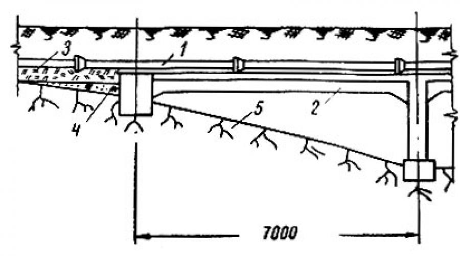
Overhead laying. This type of gasket is the most convenient to operate and repair and is characterized by minimal heat losses and ease of detection of accident sites. Supporting structures for pipes are free-standing supports or masts that ensure the pipes are located at the required distance from the ground. For low supports, the clear distance (between the insulation surface and the ground) for a group of pipes up to 1.5 m wide is taken to be 0.35 m and at least 0.5 m for larger widths. Supports are usually made of reinforced concrete blocks, masts and overpasses are made of steel and reinforced concrete. The distance between supports or masts when laying pipes with a diameter of 25-800 mm above ground is taken to be 2-20 m. Sometimes one or two intermediate suspended supports are installed using guy wires in order to reduce the number of masts and reduce capital investments in the heating network.
To service fittings and other equipment installed on the pipelines of the heating network, special platforms with fences and ladders are arranged: stationary at a height of 2.5 m or more and mobile at a lower height. In places where main valves are installed, drainage valves and air devices provide insulated boxes, as well as devices for lifting people and fittings.
5.2. Drainage of heating networks
When laying heat pipes underground, in order to avoid water penetration into the thermal insulation, an artificial lowering of the groundwater level is provided. For this purpose, together with the heat pipes, drainage pipelines are laid 200 mm below the base of the channel. The drainage device consists of a drainage pipe and a filtration material of sand and gravel. Depending on the operating conditions, various drainage pipes are used: for non-pressure drainage - socketed ceramic, concrete and asbestos-cement, for pressure drainage - steel and cast iron with a diameter of at least 150 mm.
At turns and when there are differences in pipe laying, they arrange inspection wells according to the type of sewer. In straight sections, such wells are provided at least 50 m apart. If drainage of drainage water into reservoirs, ravines or sewers by gravity is impossible, pumping stations are built, which are placed near the wells at a depth depending on the elevation drainage pipes. Pumping stations are usually built from reinforced concrete rings with a diameter of 3 m. The station has two compartments - a machine room and a reservoir for receiving drainage water.
5.3. Structures on heating networks
Heating chambers are intended for servicing equipment installed on heating networks with underground installation. The dimensions of the chamber are determined by the diameter of the heating network pipelines and the dimensions of the equipment. Shut-off valves, stuffing box and drainage devices, etc. are installed in the chambers. The width of the passages is at least 600 mm, and the height is at least 2 m.
Heating chambers are complex and expensive underground structures, therefore they are provided only in places where shut-off valves and stuffing box compensators are installed. The minimum distance from the ground surface to the top of the chamber ceiling is taken to be 300 mm.
Currently, heating chambers made of precast concrete. In some places, the chambers are made of brick or monolithic reinforced concrete.
On heat pipelines with a diameter of 500 mm and above, electrically driven valves with a high spindle are used, so an above-ground pavilion about 3 m high is built above the recessed part of the chamber.
Supports. To ensure organized joint movement of the pipe and insulation during thermal expansion, movable and fixed supports are used.
Fixed supports, intended for securing pipelines of heating networks at characteristic points, they are used for all installation methods. Characteristic points on the route of the heating network are considered to be the places of branches, the installation sites of valves, stuffing box compensators, mud traps and the installation sites of fixed supports. The most widespread are panel supports, which are used both for ductless installation and for laying heating network pipelines in non-passable channels.
The distances between fixed supports are usually determined by calculating the strength of pipes at a fixed support and depending on the magnitude of the compensating capacity of the adopted compensators.
Movable supports installed for ducted and ductless installation of heating network pipelines. Exist following types various designs of moving supports: sliding, roller and suspended. Sliding supports used for all installation methods, except channelless. Rollers are used for overhead laying along the walls of buildings, as well as in collectors and on brackets. Suspended supports are installed when laying above ground. In places where there is possible vertical movement of the pipeline, spring supports are used.
The distance between the movable supports is taken based on the deflection of the pipelines, which depends on the diameter and wall thickness of the pipes: the smaller the pipe diameter, the smaller the distance between the supports. When laying pipelines with a diameter of 25-900 mm in channels, the distance between movable supports is taken to be 1.7-15 m. When laying above ground, where a slightly larger deflection of pipes is allowed, the distance between supports for the same pipe diameters is increased to 2-20 m.
Compensators used to relieve temperature stresses that arise in pipelines during elongation. They can be flexible U-shaped or omega-shaped, hinged or stuffing box (axial). In addition, pipeline turns at an angle of 90-120° available on the route are used, which work as compensators (self-compensation). Installation of expansion joints involves additional capital and operating costs. Minimum costs are obtained in the presence of self-compensation areas and the use of flexible compensators. When developing heat network projects, a minimum number of axial compensators is used, making maximum use of the natural compensation of heat pipes. The choice of compensator type is determined by the specific conditions for laying pipelines of heating networks, their diameter and coolant parameters.
Anti-corrosion coating of pipelines. To protect heat pipelines from external corrosion caused by electrochemical and chemical processes under the influence of the environment, anti-corrosion coatings are used. Factory-made coatings are of high quality. The type of anti-corrosion coating depends on the temperature of the coolant: bitumen primer, several layers of insulation over insulating mastic, wrapping paper or putty and epoxy enamel.
Thermal insulation. For thermal insulation of pipelines of heating networks, various materials are used: mineral wool, foam concrete, reinforced foam concrete, aerated concrete, perlite, asbestos cement, sovelite, expanded clay concrete, etc. For duct installation, suspended insulation made of mineral wool is widely used, for non-channel installation - from autoclaved reinforced foam concrete, asphalt -toizol, bitumen perlite and foam glass, and sometimes backfill insulation.
Thermal insulation usually consists of three layers: thermal insulation, cover and finishing. The covering layer is designed to protect the insulation from mechanical damage and moisture, i.e. to preserve thermal properties. To construct the covering layer, materials are used that have the necessary strength and moisture permeability: roofing felt, glassine, fiberglass, foil insulation, sheet steel and duralumin.
As a covering layer for ductless installation of heat pipes in moderately humid conditions sandy soils use reinforced waterproofing and asbestos-cement plaster over a wire mesh frame; for channel installation - asbestos-cement plaster over a frame made of wire mesh; for above-ground installation - asbestos-cement half-cylinders, sheet steel casing, galvanized or painted aluminum paint.
Suspended insulation is a cylindrical shell on the surface of the pipe, made of mineral wool, molded products (slabs, shells and segments) and autoclaved foam concrete.
The thickness of the thermal insulation layer is taken according to calculation. The maximum coolant temperature is taken as the calculated coolant temperature if it does not change during the operating period of the network (for example, in steam and condensate networks and hot water supply pipes), and the average for the year if the coolant temperature changes (for example, in water networks). The ambient temperature in the collectors is taken to be +40°C, the soil on the pipe axis is the average for the year, the outside air temperature for above-ground installation is the average for the year. In accordance with the design standards for heating networks, the maximum thickness of thermal insulation is taken based on the installation method:
For overhead installation and in collectors with pipe diameter 25-1400
mm insulation thickness 70-200 mm;
In channels for steam networks - 70-200 mm;
For water networks - 60-120 mm.
Fittings, flange connections and other shaped parts of heating networks, as well as pipelines, are covered with a layer of insulation with a thickness equal to 80% of the thickness of the pipe insulation.
When laying heat pipes without ducts in soils with increased corrosive activity, there is a danger of pipe corrosion from stray currents. To protect against electrical corrosion, measures are taken to prevent the penetration of stray currents into metal pipes, or so-called electrical drainage or cathodic protection (cathodic protection stations) are installed.
The LIT information technology plant in Pereslavl-Zalessky produces flexible thermal insulation products made from foamed polyethylene with a closed pore structure "Energoflex". They are environmentally friendly, as they are manufactured without the use of chlorofluorocarbons (freon). During operation and during processing, the material does not release into the environment toxic substances and does not provide harmful effects on the human body through direct contact. Working with it does not require special tools and increased security measures.
"Energoflex" is intended for thermal insulation of engineering communications with a coolant temperature from minus 40 to plus 100 ° C.
Energoflex products are produced in the following forms:
Tubes in 73 standard sizes with internal diameters from 6 to 160 mm and
wall thickness from 6 to 20 mm;
Rolls are 1 m wide and 10, 13 and 20 mm thick.
The thermal conductivity coefficient of the material at 0°C is 0.032 W/(m-°C).
Mineral wool thermal insulation products are produced by the enterprises of Termosteps JSC (Tver, Omsk, Perm, Samara, Salavat, Yaroslavl), AKSI (Chelyabinsk), Tizol JSC, Nazarovsky ZTI, Komat plant (Rostov -on-Don), CJSC "Mineral Wool" (Zheleznodorozhny, Moscow region), etc.
Imported materials from ROCKWOLL, Ragos, Izomat and others are also used.
The performance properties of fibrous thermal insulation materials depend on the composition of the material used. various manufacturers raw materials and technological equipment and vary over a fairly wide range.
Technical thermal insulation made of mineral wool is divided into two types: high-temperature and low-temperature. The company JSC "Mineral Wool" produces thermal insulation "ROCKWOLL" in the form of fiberglass mineral wool boards and mats. More than 27% of all fibrous thermal insulation materials produced in Russia are URSA thermal insulation produced by JSC Flyderer-Chudovo. These products are made from staple glass fiber and are characterized by high thermal and acoustic characteristics. Depending on the brand of the product, the thermal conductivity coefficient
such insulation ranges from 0.035 to 0.041 W/(m-°C), at a temperature of 10°C. The products are characterized by high environmental performance; they can be used if the coolant temperature is in the range from minus 60 to plus 180°C.
CJSC "Isolation Plant" (St. Petersburg) produces insulated pipes for heating networks. Reinforced foam concrete is used as insulation here, the advantages of which include:
High maximum application temperature (up to 300°C);
High compressive strength (not less than 0.5 MPa);
Can be used for channelless installation on any depth
without laying heat pipelines and in all soil conditions;
The presence of a passivating protective layer on the insulated surface
film that occurs when foam concrete comes into contact with the metal of the pipe;
The insulation is non-flammable, which allows it to be used in all
types of installation (overground, underground, channel or non-channel).
The thermal conductivity coefficient of such insulation is 0.05-0.06 W/(m-°C).
One of the most promising methods today is the use of pre-insulated ductless pipelines with polyurethane foam (PPU) insulation in a polyethylene sheath. The use of “pipe-in-pipe” type pipelines is the most progressive way of energy saving in the construction of heating networks. In the USA and Western Europe, especially in the northern regions, these designs have been used since the mid-60s. In Russia - only since the 90s.
The main advantages of such designs:
Increasing the durability of structures up to 25-30 years or more, i.e.
2-3 times;
Reduction of heat losses by up to 2-3% compared to existing ones
20^40% (or more) depending on the region;
Reducing operating costs by 9-10 times;
Reducing the cost of repairing heating mains by at least 3 times;
Reducing capital costs during the construction of new heating mains in
1.2-1.3 times and a significant (2-3 times) reduction in construction time;
Significant increase in the reliability of heating mains constructed according to
new technology;
Possibility of using an operational remote control system
control of insulation moisture, which allows timely response
to damage the integrity of a steel pipe or polyethylene guide
insulation coating and prevent leaks and accidents in advance.
On the initiative of the Moscow Government, Gosstroy of Russia, RAO UES of Russia, CJSC MosFlowline, TVEL Corporation (St. Petersburg) and a number of other organizations, the Association of Manufacturers and Consumers of Pipelines with Industrial Polymer Insulation was created in 1999.
CHAPTER 6. CRITERIA FOR SELECTION OF THE OPTIMAL OPTION
Aboveground pipeline laying
Overhead laying of pipelines through internal plant roads and railway access roads is carried out in compliance with the following basic requirements. The intersection of roads by pipeline networks is accepted at an angle of 90° to the axis of the road, and in cases where it is impossible to meet this requirement, it is allowed to reduce the intersection angle to 45°C.
Heating networks are laid by above-ground or underground (extremely rare) methods. When laying above ground, pipelines are laid on overpasses or on free-standing supports. With the underground method, pipelines are laid in non-passable channels.
Simple suspended supports are used for overhead laying of pipelines on overpasses with guy wires in self-compensation areas or when installing U-shaped compensators. Maximum spans between suspended supports is additionally checked by calculating the maximum permissible load on the support.
In industrial buildings and structures, it is necessary to provide for the above-ground laying of pipelines (along walls, columns and other building structures), and if such placement is not possible, it is allowed to provide for the laying of pipelines in underground channels. overhead pipeline laying
When laying pipelines above ground, in order to avoid freezing of the transported medium at subzero outside temperatures, a continuous supply of steam and condensate must be provided (especially for small-diameter pipelines) or associated heating of the condensate pipelines must be provided.
Exhaust and secondary steam lines and condensate lines are, whenever possible, laid together with existing fresh steam lines, water lines and process pipelines. When the groundwater level is high, above-ground installation of steam and condensate pipelines should be preferably used.
Aboveground pipeline laying was carried out mainly on overpasses and high supports. Some domestic factories also used lowered laying (2-2.5 m from the ground level).
As a rule, above-ground installation of pipelines should be provided on overpasses or free-standing supports.
Aboveground installation of pipelines for transporting heated products should be provided on free-standing supports and overpasses with a height that eliminates the thermal impact of pipelines on permafrost foundation soils.
When laying pipelines above ground, depending on their characteristics and operating conditions, the following types of supports are used: fixed and movable (sliding, roller and suspended). Movable supports allow the pipeline to move during temperature deformations.
Aboveground laying of pipelines along racks is convenient to use, since the pipelines are accessible for repair and monitoring; however, this method is expensive and therefore has not been widely used.
For turbulent mode (pipe diameter 200-- 300 mm, g 80 ° C) Besh recommends taking the following values for k in W/m deg dry soil, sand -- 5.8 moist damp soil -- 5.8 + 11.6 soil , containing groundwater, quicksand, - 17.4 87.0. For overhead laying of pipelines in still air = 12--14 W/m deg, and in rain and wind A = 14--23 W/m deg.
Note The mass of snow and ice should be taken into account in calculations only when laying pipelines above ground outdoors.
When laying pipelines above ground through roadways and streets, the height of the pipelines (clear) from ground level to the outer surface of the insulation must be at least 4.5 m, except for laying through the railway track, when the distance from the rail head to the outer surface of the insulation should not be less than 6 m (for normal gauge). When the distance from the bottom point of the pipeline insulation to the ground level is less than 2 m, then transition stairs must be installed for the passage of people. When installing pipelines on an overpass, the edges of the latter must be at least 5 m from combustible buildings and explosive production premises from the ammonia storage warehouse - 10 m from the axis of the railway track - 3 m and from travel and pedestrian roads.
Foreign practice in the operation of chemical and oil refineries also confirms the feasibility of above-ground installation of pipelines.
Each of three types aboveground laying of pipelines (high, low and low) has its own technical and economic indicators, which serve as a criterion for choosing the optimal type of laying in specific conditions, including combined high with low, low with low, etc.
When laying a pipeline above ground, in order to maintain the brine temperature not lower than 2--3 °C, depending on local climatic conditions the pipeline should be thermally insulated or also heated. When laying the brine pipeline above ground in the southern regions, its thermal insulation is not provided.
Overhead laying of pipelines is carried out on overpasses, pile supports, along the walls of buildings and when crossing roads and ravines, in factory territories. Pipes are laid in ring thermal insulation or in insulated boxes. The above-ground laying of the pipeline is carried out on a bedding with embankment. When laying above ground, heat and waterproofing of pipelines is provided.
The disadvantage of above-ground pipeline installation is the need to allocate a strip of irrigated or arable land at least 4 m wide for permanent use.
At the intersections of overpasses on which pipelines with flammable gases are laid, railways and internal plant tracks, valves, water collectors, stuffing box compensators, flange connections and other mounting components in which leaks may occur during operation should not be installed on pipelines. In these cases, pipelines are installed only by welding. The underground or above-ground installation of pipelines with flammable gases together with telephone, power and lighting cables is not allowed.
When laying pipelines above ground on overpasses or free-standing supports, joint laying of pipelines of all categories with process pipelines for various purposes is allowed, with the exception of laying in overpass-type galleries, as well as cases where such laying contradicts the requirements of other safety rules.
Defects are eliminated when the excess pressure is reduced to zero and the compressor is turned off. During pneumatic strength tests, a protected (safe) area must be established both indoors and outdoors. The minimum zone distance must be at least 25 m for overhead pipeline installation and at least 10 m for underground installation. The boundaries of the zone are fenced off.
Deviations from the design position of the supports when laying pipelines above ground should not exceed 5 mm for the displacement of the foundations relative to the alignment axes, 10 mm for the deviation of the support axes from the vertical, and +5 mm for the elevation of the top of the supports.
Aboveground laying of pipelines on high supports is a dangerous type of work, therefore it is necessary to strictly follow all safety regulations and the requirements of the work project.
When laying pipelines above ground through passages, the height of the pipelines (in clear) from the ground level to the outer surface of the insulation must be at least 5 m, except for cases of laying through the railway track, when the distance (in clear) from the rail head to the outer surface of the pipeline insulation must be at least 6 m (for normal gauge).
When laying together overhead pipelines of large and small diameters in order to increase the distances between supporting structures (overpass masts), it is recommended to a) use large-diameter pipes Vu = 500 mn or more) as load-bearing structures to create support or hang small-diameter pipes from them b) apply local stiffening of pipes of small and medium diameters by welding stiffeners.
Fittings and instruments for ground and above-ground pipeline laying are placed in chambers-wells, chambers-booths, chambers-thermal centers.
When laying pipelines above ground, paint and varnish coatings are used, the most common of which are the following.
Aboveground laying of pipelines on low supports is provided only in cases where traffic, lifting mechanisms and equipment are not expected to move in the area of the territory through which pipelines are laid.
The above-ground pipeline laying scheme is carried out in such a way as to make maximum use of the plant territory intended for creating fire-prevention gaps between objects.
U-shaped expansion joints have a large compensation capacity (up to 700 mm) and are used primarily for above-ground laying of pipelines, regardless of their diameter.
Aboveground laying of pipelines is carried out on overpasses, pile supports, along the walls of buildings and is used when crossing roads and ravines, in factory territories. Pipes are laid in ring thermal insulation or in insulated boxes.
The assignment for the development of drawings of canals and overpasses is drawn up on the basis of the routing of the main technological lines and regulatory guidelines for underground and above-ground laying of pipelines. As a rule, water conduits and sewer lines are laid in intra-shop channels. The cross-sectional dimensions of the channel should ensure ease of installation and repair of pipes, placement of separate branches to process equipment, placement of primary elements of instrumentation and control equipment (diaphragms, water meters, etc.) and installation of shut-off valves.
The laying of pipelines can be underground (in through-channels - tunnels, non-through-through channels and cable-free - directly in the ground), above-ground on supports and above-ground - on overpasses. Ground and above-ground laying of pipelines is preferable, since it provides the possibility of visual monitoring of the condition of pipelines and facilitates their installation and repair. Laying pipelines in the ground, especially gas pipelines, is dangerous because leaks can travel significant distances from the point of damage to the pipeline, and determining the location of the leak is difficult and common.
Before filling the pipelines with coolant, they are thoroughly washed and the tightness of the bolts on the flange connections is checked, the operation of shut-off valves, air bleed valves, drainage devices, the packing of oil seals on compensators, gate valves and valves, the presence of necessary places sleeves for thermometers and fittings for pressure gauges, accessibility and uncluttered premises of subscriber inputs. When laying pipelines above ground, the condition of the supporting structures and the correct installation of movable supports are also checked.
Underground or above-ground laying of pipelines with flammable gases together with telephone, power and lighting cables is prohibited.
Fire hydrants are installed on main sections of networks. It is advisable to lay above-ground pipelines in earthen ridges, buried channels using continuous backfill, as well as in semi-buried channels. Aboveground installation of pipelines is carried out on low supports, masts, overpasses or in ventilated undergrounds of buildings, in heated rooms and insulated ducts.
§ 2. Methods of underground, above-ground and above-ground laying and their technical and economic indicators
The installation of sanitary and technical communications in areas of permafrost can cause the soil to thaw due to the heat generated by the pipelines. As a result, the stability of both the pipelines themselves and buildings may be compromised. Methods for laying sanitary and technical communications must be linked to the methods of construction of buildings and structures and depend on the properties of the foundation soils and other factors, the most important of which is the location of the network route in relation to the built-up area and its architectural and planning solution.
Exist the following types laying of sanitary and technical communications: underground, above-ground and above-ground. These types of gaskets, in turn, can be single or combined.
Ground and overhead laying Due to the absence of contact of pipes with the ground and limited heat release into the soil, the foundations disturb to the least extent the natural thermal regime of permafrost soils. Such gaskets clutter the territory of populated areas, complicate the construction of passages, the organization of snow protection and snow removal.
Underground laying it is advisable to carry out within the boundaries of the development settlement in order to achieve maximum improvement of the territory. Water supply and sewer networks can be laid directly in the ground, and heating networks and steam pipelines can be laid in special channels. If there are such channels, it is advisable to lay water supply, sewerage and electrical cables in them.
The underground installation of heating networks is very expensive and requires special measures to maintain the thermal regime of permafrost soils at the base of the networks. So, for example, the cost 1 linear m channel for district heating in the conditions of Norilsk averages 300 rubles. The cost of a two-tier channel for the combined installation of a heating network, water supply, sewerage and electrical cables under the same conditions averages about 450 rubles. behind 1 linear m. Therefore, underground installation of heating networks is advisable only in compact buildings with multi-story (4-5 floors) buildings and in conjunction with other communications.
If the development is carried out with two- and three-story buildings with gaps, then the underground installation of heating networks usually turns out to be economically infeasible. In such cases, above-ground laying is most often used along the facades and attics of buildings, and between buildings - along overpasses, fences and fences. In this case, water supply and sewerage can be laid in the ground without channels. If the soils of the base of the pipes are subsidence, then to ensure their stability it is necessary to replace the soils with non-subsidence ones to a depth determined by thermal engineering calculations.
For small villages, if it is possible to route the network within blocks without crossing streets or with a minimum number of intersections, the most economical option is to lay heating networks above ground in ring insulation or in insulated ducts together with a water supply system. In this case, the sewerage system must be laid in the ground without channels.
In soils that subsidence during thawing, especially in soils that transform during thawing into a fluid-plastic or fluid state, when laying underground pipelines, an artificial foundation is necessary. The cost of such a foundation is directly dependent on the depth of thawing of the soil under the pipes.
When laying pipelines in soils that do not settle and do not lose their bearing capacity when thawed, the decisive condition is to protect them from freezing by reducing heat loss. In this case, the depth of placement is increased to 1.5-2.0 m; greater depth is undesirable, as it makes it difficult to detect pipeline failure sites and repair them, both in summer and especially in winter.
In order to reduce heat loss and the size of the taliks under the pipes, underground laying of water supply and sewerage systems is used in thermal insulation: in boxes made of wood or reinforced concrete filled with sawdust or mineral wool, in a ring box made of foam concrete, mineral wool, felt impregnated with resin. All of these types of thermal insulation fail to achieve their goal when the insulating material is wet. Local faults in waterproofing (and therefore thermal insulation) lead to thawing of the base and uneven settlement of pipelines, which is the most undesirable. Restoring thermal and waterproofing during repairs is a complex and labor-intensive process. The use of boxes creates additional difficulties in detecting and eliminating leaks. Any leak entails a violation of thermal insulation. The cost of thermal insulation usually exceeds the cost of an artificial foundation for water supply and sewerage. That's why wide application thermal insulation for water supply and sewerage pipelines when laying them in the ground is impractical.
Let's consider some designs of pipeline foundations laid in the ground.
Soil foundation(Figure IV-1). Ice-saturated local soils at the base of the fuel pipeline are replaced by non-subsidence soils with a low filtration coefficient to the calculated thawing depth. Sandy, gravel-sandy soils in some cases are compacted by preliminary thawing. For replacement, light sandy loams and fine-grained silty sands in a thawed state are used; in this case, an admixture of pebbles, gravel, crushed stone up to 40.....-45% or local dehydrated and compacted soil is desirable. A waterproofing layer of adobe concrete or clay with a thickness of 25-30 cm.
The width of the artificial foundation is assumed to be equal to the width of the trench, and the height is determined by calculation.
In the absence of a leak, the radius of thawing from heat releases from water supply or sewer pipelines on average does not exceed 1.2 m. If we take into account the increased intensity of thawing of soils that replace ice-saturated soils, then the depth of replacement will not exceed 1.5 m. It must be assumed that in many cases the soil foundation will be economically beneficial and technically feasible.
Flat base It is used to reduce the unevenness of subsidence during thawing of subsidence soils and is made in the form of longitudinal logs in two logs. To prevent the tracks from warping during subsidence, as a result of which the pipeline is destroyed, they must be securely fastened.
Floating base used in ice-saturated soils and is a continuous flooring of plates laid across the trench; this type of foundation is quite reliable, but cannot be widely recommended due to its high cost and consumption large quantity timber.
>
Rice. IV-2. Pipeline on a pile foundation. 1 - pipeline; 2 - log (timber) ∅30 cm on dowels (staggered joints); 3 - piles ∅30 cm through 3m with recess on 3m below the active layer; 4 - gaskets through 10 cm; 5 - backfilling with local soil
Pile foundation(Fig. IV-2) is used in highly subsidence soils. Driving piles into permafrost soil requires labor-intensive and expensive work on steaming the soil or drilling wells. Piles have to be placed frequently, because in pipes that carry a large load from the soil, significant bending moments occur on the supports. Such bases are characterized by high cost.

Underground overpasses(Fig. IV-3) due to their high cost, they are used in exceptional cases, for example, for sewerage in subsidence soils that thaw to great depths, when the route passes near a building with large heat releases, built according to methods I or IV and located higher in the relief.
The issue of using one or another type of basis is resolved by comparing technical and economic indicators.
To eliminate the possibility of intense movement of supra-permafrost water flow along underground pipelines, clay concrete bridges are used across the trenches. The lintels cut into the frozen base and walls of the trenches on 0.6-1.0 m. The distance between the lintels is determined depending on the longitudinal slope so that the pressure at the lintel does not exceed 0.4-0.5 m; Typically this distance ranges from 50 to 200 m.
In pebble, gravel and other well-filtering soils, the installation of dams is not advisable, since the flow of supra-permafrost water easily bypasses them.
Laying in earthen beads
>
Rice. IV-4. Laying pipes in earthen beads. 1 - pipeline; 2 - thick clay concrete layer 20 cm; 3 - local soil; 4 - sand and gravel layer; 5 - local dewatered and compacted soil
This installation method (Fig. IV-4) is used under fairly favorable permafrost-soil conditions, in the absence of thermal insulation materials on site, and the pipeline route must pass through an undeveloped area. This type of gasket has several advantages:
- there is no need to carry out labor-intensive earthworks of digging trenches;
- pipe leaks are easier to detect and fix;
- filtering of supra-permafrost water along the pipes is eliminated;
- the presence of a talik around the pipes allows longer interruptions in the movement of water through them than with ground and above-ground installations;
- there is no need for thermal and waterproofing of pipes.
Main disadvantages this method is excessive cluttering of the territory and the complexity of crossings. In addition, this creates conditions for greater snow cover in the area.
Underground laying of pipelines in channels
Laying pipelines in underground channels is a relatively expensive type of network construction; nevertheless, in a number of cases, channel laying is advisable, if we take into account not only one-time capital investments, but also operating costs. The feasibility of combined laying of communications in underground channels in comparison with a single underground one should be confirmed by the cost of construction attributed to 1 m2 living space, and reliability in the operation of utility networks. Combined laying is usually justified in unfavorable climatic and frozen soil conditions.
Channels can be pass-through (semi-pass-through) and non-pass-through, single-tier and two-tier. In two-tier channels, the lower tier of which is passable, the upper tier can be either semi-passable or non-passable. Channel design with semi-bore top tier bulky and high cost. The single-tier channel design is the most economical and convenient to use.
In the case of installing different types of canals in a populated area (which must be justified), it is necessary, based on the conditions of industrialization of construction, to achieve minimum quantity standard sizes of elements.

Impassable up to 0.9 m channels (Fig. IV-5) can be used in short sections (house outlets and inlets, road intersections, etc.) while ensuring stability conditions and operating requirements. Non-passable channels should be constructed with minimal penetration into the ground (no more than 0.5-0.7 m from the floor to the ground surface). They must have a removable cover for cleaning channels, inspecting and repairing pipelines. The longitudinal slope of non-passable channels to ensure water drainage along the bottom must be at least 0.007.

Passage channels with a height of at least 1.8 m(Fig. IV-6) must have dimensions that provide free passage through them for inspection and repair of pipes, fittings and electrical cables.
>
Rice. IV-7. Reinforced concrete two-tier passage channel. 1 - sewerage; 2 - heating network: 3 - water supply; 4 - shelves for electrical and communication cables; 5 - sand, δ = 10 cm; 6 - clay concrete, δ = 20 cm; 7 - replaced soil (calculated thickness)
With significant channel depths and large heat releases from communications, taliks formed under the channels can reach significant sizes. In such cases, to reduce the penetration of heat into the base, based on a technical and economic comparison with other options, the feasibility of installing two-tier channels is revealed (Fig. IV-7). In the lower passage tier of such a channel, a sewer pipeline and electrical cables are placed, in the upper - non-passable or semi-passable - heating network and water supply pipes are laid.
When laying a combined sewer and water supply system, water valves must be placed in special chambers or sections isolated from the sewer pipeline.
In order to prevent destruction of both the canals themselves and nearby buildings and structures from thawing of the soil at the base, it is necessary:
- thermally insulate pipelines, minimizing their heat generation as much as possible;
- ventilate the channels in winter to remove heat so that the soils at their base that have thawed over the summer are completely frozen;
- arrange waterproofing along the bottom of the canal, preventing water from penetrating into the foundation soils. The foundations under the canals should be made of non-subsidence or low-subsidence soils.
In addition to replacing subsidence soils, it is possible to use preliminary thawing and compaction of foundation soils. Channels must be made of reinforced concrete, reinforced cement or other effective material. The construction of channels made of wood or concrete may be allowed with special justification, since concrete channels roads and do not meet the strength requirements for uneven settlement of the base, and wooden ones are susceptible to rotting, require extensive waterproofing work, and become silted with tiny soil particles; If they have sewerage, they create unsanitary conditions for the water supply.

Ventilation of channels is arranged natural and artificial (forced). Natural is carried out by device ventilation holes along the top of the channel at a distance 20-25 m depending on the dimensions of the channel and communications laid in it (Fig. IV-8). The efficiency of natural ventilation can be increased by installing exhaust shafts in buildings located near the canal; in this case, the distance between the holes on the channel for air flow can be increased to 100-150 m.
Discharge of emergency or waste water from the canal should be carried out from its end part, using a longitudinal slope, or from intermediate water collectors (waterproof pits) by pumping water out with pumps.
Heat and steam pipelines placed in channels should be moved as far as possible from the bottom of the channel; they must be in ring thermal insulation (for example, foam concrete with asbestos-cement plaster and waterproofing). The use of plastics with increased heat and waterproofing properties (foam plastic, polyethylene, etc.) for these purposes has great prospects.
The technical and economic feasibility of laying sewer networks in canals together with networks for various purposes in comparison with a single underground laying is revealed based on a comparison of the cost of construction and operation, attributed to 1 m2 living space, as well as assessing the stability of networks, their durability and thermal impact on nearby buildings and structures.
Ground laying of pipelines
The above-ground type of installation usually includes pipelines laid on low supports. In this case, between the pipe and the ground surface there must be a ventilated space of at least 30 cm, which is necessary to reduce heat release into the foundation soils and prevent snow drifts.
Ground laying of pipelines should be used outside the built-up areas of populated areas (as it is the cheapest), in low-lying and swampy sections of the route, in places with heavily ice-saturated permafrost soils.
In the built-up area, ground installation is allowed if there are a small number of pipeline intersections with driveways and sidewalks. Pipelines are thermally and waterproofed. The use of combustible materials both for the manufacture of ducts and heat-insulating backfills for steam pipelines and heating networks at a coolant temperature of 90 °C and above is not recommended by fire regulations. Slag backfill should also not be widely used due to the possible destruction of metal pipes by corrosion when the slag is moistened.
Wooden boxes, being in conditions of variable humidity, are deformed, the filling is blown out, spills out and is easily moistened. Waterproofing boxes with roll materials does not achieve the goal, since roll coverings are easily damaged. Therefore, boxes made of reinforced concrete are more reliable, but their cost with backfill is higher than the cost of ring heat and waterproofing of pipes.
In the case of combined installation, mainly for ease of use, thermal insulation is carried out independently for pipelines for various purposes.
The base for above-ground pipelines can be bulk sand-gravel or any other non-subsidence or low-subsidence soil, laid without disturbing the natural moss and vegetation cover during the work. In the case of subsidence soils of the natural foundation, it is necessary to replace them with non-subsidence ones to a depth determined by calculation.
Special supports are installed on an artificial soil foundation under the pipelines.
Leg supports of the transverse beams have a small height, as a result of which, when the supports settle, the thermal insulation of the pipes falls on the ground, easily becomes moistened and deteriorates. The installation of common supports for several pipelines is not recommended, since with uneven load the tracks give uneven settlement.

Town supports(Fig. IV-9) are a more advanced type of wooden supports; they make it easy to straighten the profile of pipelines in the event of small subsidence of the foundation by wedging the elements of the towns.

Reinforced concrete intermediate supports sliding and roller type (Fig. IV-10) are more economical and durable than wooden ones. Their disadvantage is the difficulty of straightening pipelines when embankments settle; To level the base, the pipeline must be lifted and the supports removed.

Fixed(anchor) supports(Fig. IV-11) are made of wood, concrete and reinforced concrete. With wooden supports, the pipes are secured to the support beams with bolts or pins.
Frame fixed supports require large volumes of work to develop and excavate soil from pits. Therefore, they can be recommended in cases where the use of pile supports is impractical (active layer high power, high-temperature frozen soils characterized by low freezing forces, boulder crushed soils, etc.).
Massive concrete supports are arranged for pipelines of large diameters and during the construction of pipelines in 2 stages. For fastening metal parts, nests are left in the concrete mass, which must be filled with concrete of the lowest grades until the construction of the second stage pipeline. Otherwise, water accumulates in them, which, when frozen, can tear the concrete mass. To avoid thawing of the foundation soil due to exotherm during concrete hardening, as well as from heat flow through the support body, a sand cushion of thickness is laid on the bottom of the pit 20-30 cm.
In general, ground laying in the conditions of the Far North is the most economical type of laying sanitary and technical communications (excluding sewerage).
Aboveground pipeline laying

Aboveground laying of pipelines is carried out on overpasses, on pile supports rising above the terrain (Fig. IV-12), along the walls of buildings, attics and fences. The above-ground type of pipeline laying is used when crossing roads, hollows, ravines and streams, in factory areas, and in places with heavily ice-saturated permafrost soils.
Similar to above-ground installation, pipes are laid in ring thermal insulation or in insulated boxes.
Overpasses can be made of wood, reinforced concrete and metal. Metal trestles are used in flammable areas. The production of reinforced concrete overpasses is difficult and their cost is high. Therefore, pile and frame wooden trestles are mainly used.
Advantages of above-ground installation:
- pipes and ducts do not cause snow deposits and do not interfere with snow removal;
- the issue of intersections with driveways and walkways is successfully resolved;
- pipes and their insulation are not exposed mechanical damage from transport and pedestrians;
- pipelines are not subject to snow drifts and are easily accessible for inspection and repair.
Disadvantages of above-ground installation:
- high cost compared to land installation;
- inconvenience of installing fittings, especially fire hydrants;
- more significant heat losses than during ground installation due to high wind speeds and the absence of snow deposits on the pipes;
- pipes laid along building facades, overpasses and fences spoil the appearance of a populated area;
- When laying pipes along the walls of buildings, the principle of priority for the construction of sanitary communications is violated.
Technical and economic indicators for some types of gaskets are given in Appendices 1 and 2.