Cascade connection of boilers. Features of cascade connection of gas boilers How to make a boiler chimney in a cascade
Let's start with the fact that modern house, located with middle lane, there should be 2 boilers. It’s not even necessary to have 2 boilers, but two independent sources of thermal energy – that’s for sure.
We have already written about what kind of boilers or energy sources these could be in the article “”. It describes in more detail which boiler and which backup is needed and can be selected.
Today we’ll look at how to connect 2 or more heat generators into a single heating system and how to connect them. Why am I writing about 2 or more units? thermal equipment? Because there can be more than 1 main boiler, for example two gas boilers. And there may also be more than 1 backup boiler, for example, on different types fuel.
Connecting two or more main heat generators
Let us first consider a scheme in which we have two or more heat generators, which are the main ones and, when heating the house, operate on the same fuel.
These are usually connected in a cascade in order to heat rooms from 500 sq.m. total area. Quite rarely, solid fuel boilers are combined together for main heating.

We are talking specifically about the main heat generators and heating of residential premises. For cascade and modular boiler houses for heating large industrial premises may include “batteries” of coal or fuel oil boilers in quantities of up to one dozen.
So, as mentioned above, they are connected in a cascade, when a second identical boiler or slightly less powerful one complements the first heat generator.
Usually, during the off-season and mild frosts, the first boiler in the cascade operates. In cold weather or when it is necessary to quickly reheat the premises, a second boiler in the cascade is connected to it to help.
In a cascade, the main boilers are connected in series to be heated by the first heat generator. At the same time, of course, in this combination it is possible to isolate each boiler and a bypass, which allows water to bypass the isolated boiler.
In case of problems, any of the heat generators can be turned off and repaired, while the second boiler will regularly heat water in the heating system.
There is no special alternative to this system. As practice shows, it is better and more reliable to have 2 boilers with a capacity of 40 kW each than one boiler with a capacity of 80 kW. This allows you to repair each individual boiler without stopping the heating system.
It also allows each of the boilers to operate at its full power if necessary. While 1 boiler high power would work only at half the power and at an increased clock rate.
Parallel connection of boilers - pros and cons
We reviewed the main boilers above. Now let's look at connecting backup boilers, which should be in the system of any modern home.
If backup boilers are connected in parallel, then this option has its pros and cons.

pros parallel connection reserve boilers are as follows:
- Each boiler can be connected and disconnected from each other independently.
- Each heat generator can be replaced with any other equipment. You can experiment with boiler settings.
Disadvantages of parallel connection of backup boilers:
- We'll have to work more with boiler piping, more soldering polypropylene pipes, more welding of steel pipes.
- As a result, more materials, pipes and fittings, and shut-off valves will be wasted.
- The boilers will not be able to work together, in unified system, without use additional equipment- hydraulic guns.
- Even after using the hydraulic arrow, there remains the need for complex configuration and coordination of such a boiler system according to the temperature of the water supply to the system, and.
The indicated pros and cons of parallel connection can be applied both to the connection of the main and backup heat generators, and to the connection of two or more backup heat generators using any type of fuel.
Serial connection of boilers - pros and cons
When serial connection two or more boilers, they will operate in the same way as the main boilers connected in cascade. The first boiler will heat the water, the second boiler will reheat it.

In this case, you should first install the boiler on the cheapest type of fuel for you. This can be a wood, coal or waste oil boiler. And behind it, in a cascade, there can be any backup boiler - be it diesel or pellet.
The main advantages of parallel connection of boilers:
- In the case of operation first, the heat exchangers of the second boiler will play the role of a kind of hydraulic separator, softening the impact on the entire heating system.
- The second reserve boiler can be turned on to reheat the water in the heating system in the coldest weather.
Disadvantages when using the parallel method of connecting backup heat generators in the boiler room:
- Longer path of water through the system with more turns and narrowing in connections and fittings.
Naturally, you cannot directly let the supply from one boiler enter the inlet of another. In this case, you will not be able to disconnect either the first or the second boiler, if necessary.

Although from the point of view of coordinated heating of boiler water, this method will be the most effective. This can be achieved by installing bypass loops for each boiler.
Parallel and series connection of boilers - reviews
And here are a couple of reviews from users about parallel and series connection of heat generators in a heating system:
Anton Krivozvantsev, Khabarovsk region: I have one, it is the main one and heats the entire heating system. I'm happy with Rusnit, it's a normal boiler, in 4 years of operation 1 heating element burned out, I changed it myself, that's all for 30 minutes with a smoke break.
The KChM-5 boiler, into which I built it, is paired with it. The locomotive turned out to be a great one, it heats perfectly and, most importantly, the automation of the process is almost the same as that of an automatic pellet boiler.
These 2 boilers work in pairs, one after the other. The water that Rusnit did not heat is heated by the KChM-5 and the Pelletron-15 pellet burner. The system turned out the way it needed to be.
There is another review, this time about the parallel connection of 2 boilers in the boiler room:
Evgeny Skomorokhov, Moscow: My main boiler is, it runs mainly on wood. My backup boiler is the most common DON, which is connected to the system in parallel with the first one. It rarely lights up, and anyway, I inherited it along with the house I bought.
But 1 or 2 times a year, in January, you have to flood the old DON, when the water in the system almost boils, but the house is still a little cold. This is all due to poor insulation; I haven’t completely finished insulating the walls yet, and it would be nice to insulate the attic floors better.
When the insulation is completed, I think I won’t heat the old DON boiler at all, but I’ll leave it as a backup.
If you have comments on this material, please write them in the comment form below.
More on this topic on our website:
-
Words " gas boilers“single-circuit floor heating” are unfamiliar to an inexperienced person and sound outrageously incomprehensible. Meanwhile, intense suburban construction popularizes... -
Buderus boilers Logano G-125 running on liquid fuel, are available in three capacities - 25, 32 and 40 kilowatts. Their main... -
The principle of operation of any gas boiler is that as a result of combustion gas fuel, is formed thermal energy, which is transferred to the coolant... -
Water floor heating convectors heat a room of any size evenly and in a short period of time. From the point of view of interior aesthetics, such...
As a rule, gas boilers in private homes are connected to one circuit. But this connection method has its drawbacks. It is much more effective when the system involves the use of several devices. The boiler piping scheme itself in this case can be cascaded.
Features of cascade connection
When gas boilers are connected to the heating circuit in series and form stage by stage, this is very convenient. At the same time, the control of the cascade cycle is general, and the owner can independently configure the system parameters based on the conditions. While other parameters are adjusted automatically. Experts call this configuration method flexible.
Gas boilers connected according to the cascade principle can be used to solve heating issues in residential buildings, with total area no more than 500 square meters. And although these figures are not mandatory for use, the owner independently decides the advisability of installing an additional boiler if the area to be heated is larger.
In any case, gas boilers connected using the cascade principle are very efficient to use. Those who install them will be able to feel this very soon.
What is needed for cascade connection
If you plan to connect gas boilers using a cascade type, you will need to decide on your own optimal scheme and calculate its parameters, taking into account everything professional assessments important factors. For example, turning on boilers may be possible in a sequential way, without additional equipment, only if the pump of each gas boiler can pump coolant through the heating circuit. For a residential building small area this is quite enough.
But, if gas boilers are used for big building consisting of several floors, it is necessary to use a special hydraulic separator. This will allow you to optimize financial expenses, guarantees more high comfort and rational consumption of blue fuel.
Cascading boilers- this is one of the heat generator connection schemes, thanks to which the unit power of each heating device increases. This connection method is justified and effective when there is a large heat load, as well as if, in order to reduce heating costs, boilers operating on different types of fuel are installed. The essence of this scheme is as follows - the total heat load is divided between several independently controlled heat generators, after which only those that meet the needs for heat production in a given period of time are included in the cascade. Serial or cascade connection of boilers is usually divided into “stages”, each of which has a separate heater, and all stages together form the total power of the heating network.
In most cases, functioning standard systems heating and hot water supply is provided by one boiler, the selection of which is made based on the requirements of the maximum possible load for it. However, the actual situation may differ greatly from preliminary calculations. As practice proves, in most cases, throughout heating season heating equipment operates at no more than 50% of its capacity 80% of the time. Moreover, if we consider the entire season of operation of such devices, then the average load on them ranges from 25 to 45%. Thus, one high-power heat generator will consume excess fuel and will not be able to effectively compensate for heat costs. This is due to the above indicators of uneven and often low load. The answer to this problem may be a cascade connection of boilers.
Adjustment of such a heat supply system is carried out using a special microcontroller or intelligent controller. Its task is to monitor the temperature of the coolant and determine how many stages need to be turned on in order to maintain this temperature at a given level. Thanks to this regulation, the boiler cascade ensures smooth operation of all components of the heating system required power(in a wide range), regardless of the seasons. This process occurs due to the sequential connection of several heat generators - one after the other. Cascade control in combination with program controlled allows you to solve the problem of determining the best ratio of the power of the boiler and heating system. This operating principle allows you to save energy resources without reducing comfortable temperature indoors. This effect is achieved due to the fact that the cascade boiler room is able to operate for a long time at low coolant temperatures during the off-season and during the warm winter months.
Based on the information above, it becomes clear that a sequential connection diagram with several heaters instead of one can much better provide the design loads of the heating system. Therefore, an assumption may arise that the more steps there are in a given scheme, the more efficiently it will begin to function. However, this is not quite true. The thing is that along with the increase in the number of such thermal stages, the surface areas through which heat transfer occurs will also increase. Simply put, thermal energy losses through boiler casings will increase. Ultimately, this may cancel out all the benefits from increasing efficiency cascade system boiler connections. Therefore, it is considered inappropriate to use more than four stages in this circuit.
Advantages of cascade connection of boilers and its disadvantages
Serial or cascade connection of boilers has a large number of advantages, including the following:

As for the disadvantages cascade connection, then there are also several of them. Firstly, the cost of the heating system increases due to the installation of several boilers and additional equipment to control the serial connection. Secondly, such a number of devices requires more space in the boiler room than is necessary when installing one large and powerful heater. And thirdly, connecting the cascade of boilers to the chimney becomes somewhat more complicated.
Types of cascade connection of boilers
This type of connection of heat generators is divided into three types, based on the method of operation of their burners. Types of series connection of boilers are as follows: 
- Simple cascade- it includes heat generators having single-stage or two-stage burners. Such a system is capable of increasing the power of each heater;
- Mixed cascade- this type of connection includes different heat generators, one of which features a modulating burner. In this case, it is on such a heater that a boiler water temperature control system is installed;
- Modulating stage- it includes only heat generators with modulating burners. Positive difference of this type connection from the previous two is that in it the fuel supply is adjusted smoothly, and there is also the ability to change the heat output over a wide range.
It is easy to notice that the main difference between the three types of cascade connection of boilers is what burner devices they are equipped with. The fact is that it is the burners that have a great influence on the functioning of the heating system. Thus, a simple cascade scheme allows you to regulate heat production exclusively step by step. Therefore, the most optimal type series connection of boilers is considered a modulated cascade, even taking into account the fact that the use of more than two stages reduces the performance of each heater individually. The thing is that units with modulating burners make it possible to continuously change the power of the system, based on the needs for thermal energy. This operating principle allows you to reduce fuel consumption and, consequently, save on heating.
Conditions for creating a modulated cascade
According to the information above, it is the modulated cascade that can be called the most effective of all three types of such connections. However, its implementation depends on three conditions, the fulfillment of which must be provided for at the design stage.

Hydraulic separator low pressure or hydraulic arrow - this is a modern and important element cascade connection. Its purpose is to separate the primary and secondary circuits (that is, the circuits of boilers and consumers), creating a zone for reducing hydraulic resistance. Thanks to this, the coolant flow in these two circuits will depend solely on the performance of the circulation pumps, which will not influence each other. Such a separator creates a hydraulic and temperature balance of the circuits. Hydraulic boom allows you to maintain constant flow coolant in the primary circuit, and in the secondary circuit - to effectively regulate it taking into account the thermal load. This function has already become a standard for modern heating networks. The choice of hydraulic separator or arrow is made according to the catalog, based on required power heat generator and the maximum possible coolant flow in the system.
Installation of cascade connection of boilers
Installation of a cascade of heat generators is carried out in several stages, each of which includes approximately the following actions:

Cascading boilers is a rather complex matter, during the implementation of which it is necessary to take into account a large number of various nuances. Therefore, the creation of a heat supply system of this type should be trusted only to qualified specialists who can perform all the work at the proper level. Both the development and installation of cascade connection of boilers must be carried out by companies and professionals who know the specifics of such schemes, as well as having the appropriate licenses and approvals. Attention to all details and a responsible approach to the implementation of serial connection of heat generators will help create a reliable, efficient and safe heating system, which will also be economical.
The most efficient heating system is one in which the coolant becomes hot due to the operation of two or three boilers. However, they can be the same in power and type. This rationality is explained by the fact that one heat generator operates on full power only a few weeks a year. At other times, you need to reduce its productivity. And this leads to a drop in its efficiency and an increase in heating costs.
Several combined ones allow you to more flexibly control the operation of the piping without loss of efficiency, since it is enough to turn off one or two devices. In addition, if one of them breaks down, the system continues to raise the temperature in the house.
Types of connection of two or more boilers
Using a larger number of identical boilers requires a special connection diagram. You can combine them into one system:
- Parallel.
- Cascade or sequentially.
- According to the scheme of primary-secondary rings.
Features of parallel connection
The following features exist:
- The hot coolant supply circuits of both boilers are connected to the same line. These circuits must have safety groups and valves. Latest can be closed manually or automatically. The second case is only possible when automation and servos are used.
- join another line. These circuits also have valves that can be controlled by the above-mentioned automation.
- The circulation pump is located on the return line in front of the junction of the return pipes of the two boilers.
- Both lines are always connected to hydraulic collectors. On one of the collectors there is expansion tank. In this case, a make-up pipe is connected to the end of the pipe to which the tank is connected. Of course, at the junction there are check valve And shut-off valve. The first does not allow hot coolant to enter the make-up pipe.
- Branches extend from the collectors to the radiators, heated floors, . Each of them is equipped with its own circulation pump and coolant drain valve.
Using such a piping arrangement without automation is very problematic, since it is necessary to manually close the valves located on the supply and return pipes of one boiler. If this is not done, the coolant will move through the heat exchanger of the switched off boiler. And this turns out:
- additional hydraulic resistance in the water heating circuit of the device;
- an increase in the “appetite” of the circulation pumps (they must overcome this resistance). Accordingly, energy costs are rising;
- heat losses for heating the heat exchanger of a switched-off boiler.
Read also: Heating a house with an air-heating boiler
Therefore, it is necessary to correctly install the automation, which will cut off the switched-off device from the heating system.
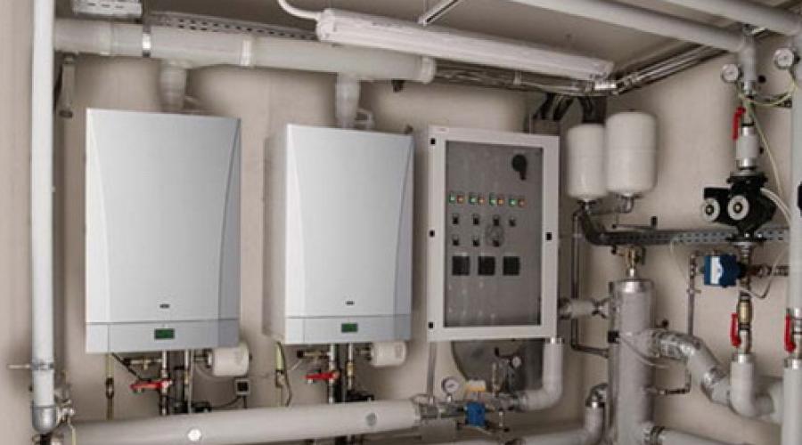
Cascade connection of boilers
 The cascading boiler concept provides distribution of heat load between several units, which can work independently and heat the coolant as much as the situation requires.
Can be cascaded like boilers with stepped gas burners, and with modulated ones. The latter, unlike the former, allow you to smoothly change the heating power. It is worth adding that if boilers have more than two stages of gas supply regulation, then the third and remaining stages make their productivity less. Therefore, it is better to use units with a modulating burner.
With a cascade connection, the main load falls on one of two or three boilers. The additional two or three devices turn on only when needed.
The features of this connection are as follows:
- The wiring and controllers are designed so that in each unit it is possible to control the coolant circulation. This allows you to stop the flow of water in disconnected boilers and avoid heat loss through their heat exchangers or casings.
- Connecting the water supply lines of all boilers to one pipe, and the coolant return lines to the second. In fact, the connection of boilers to the mains occurs in parallel. Thanks to this approach, the coolant at the inlet of each unit has the same temperature. This also avoids the movement of heated fluid between disconnected circuits.
The advantage of parallel connection is preheating the heat exchanger before turning on the burner. True, this advantage occurs when burners are used that ignite the gas with a delay after turning on the pump. Such heating minimizes the temperature difference in the boiler and avoids the formation of condensation on the walls of the heat exchanger. This applies to a situation where one or two boilers have been turned off for a long time and have had time to cool down. If they have recently turned off, then the movement of the coolant before turning on the burner allows you to absorb the residual heat that is preserved in the firebox.
Read also: Solid fuel cast iron boiler
Piping boilers with cascade connection
Its scheme is as follows:
- 2–3 pairs of pipes extending from 2–3 boilers.
- Circulation pumps, check valves and shut-off valves. They are on those tubes that are designed to return the coolant to the boiler. Pumps may not be used if the unit design includes them.
- Shut-off valves on hot water supply pipes.
- 2 thick pipes. One is intended for supplying coolant to the network, the other for return. Corresponding tubes extending from the boiler devices are connected to them.
- Security group on the coolant supply line. It consists of a thermometer, a calibration thermometer sleeve, a thermostat with manual release, a pressure gauge, a pressure switch with manual release, and a reserve plug.
- Hydraulic low pressure separator. Thanks to it, pumps can create proper circulation of coolant through the heat exchangers of their boilers, regardless of what the flow rate of the heating system is.
- Heating network circuits with shut-off valves and a pump on each of them.
- Multi-stage cascade controller. Its task is to measure the coolant at the cascade output (often temperature sensors are located in the safety group area). Based on the information received, the controller determines whether to turn on/off and how the boilers combined into one cascade circuit should operate.

Without connecting such a controller to the piping, operation of boilers in a cascade is impossible, because they must work as a single unit.
Features of the scheme of primary-secondary rings
This scheme provides primary ring organization, through which the coolant must constantly circulate. Heating boilers and heating circuits. Each circuit and each boiler is a secondary ring.
 Another feature of this scheme is the presence circulation pump in every ring. The operation of a separate pump creates a certain pressure in the ring in which it is installed. The assembly also has a certain effect on the pressure in the primary ring. So, when it turns on, water comes out of the water supply pipe, entering the primary circle and changing the hydraulic resistance in it. As a result, a kind of barrier appears on the path of coolant movement.
Cascade boiler house schemes in one form or another have existed throughout virtually the entire history of the existence of this technology, regardless of the type of fuel and scope of application. Typically, the need to use such solutions was associated with limiting the power of an individual boiler unit or the range of operating modes permissible for it. However, with the development of technologies used both in the thermomechanical part of boiler design and in the field of automation, the use of cascade solutions is increasingly becoming not a forced measure, but the most technically and economically feasible choice.
In this article we will look at the main advantages of using , various thermomechanical schemes and automation issues of such boiler houses.
We will not focus on the advantages of a separate condensing boiler before non-condensing (traditional). Somehow significantly greater efficiency and fault tolerance. However, we note the benefits of using such boilers in a cascade.
The main advantages of using boiler cascades
Most of the advantages listed below can be attributed not only to condensing boilers, but we will separately pay attention to what specifically distinguishes this type techniques within the relevant topic.
Increasing the overall power modulation range
As noted above, main reason for installing several boilers in a cascade - increase maximum power boiler room with restrictions on the performance of an individual unit. From this point of view, any boilers are, one might say, in an equal position.
At the same time, we should not forget that modern systems heating supplies are presented increased requirements in terms of energy efficiency. And one of the main principles in ensuring this principle is to ensure that the current power of heat generators is equal to the needs of the system, no more and no less. Accordingly, the lower limit of boiler room performance modulation also plays an important role. The use of a cascade helps to significantly reduce this limit. It is also worth remembering that for mid-latitudes, for most of the year, the need for heat is no more than 30-40% of the maximum.
When using identical heat generators in a cascade, the lower power limit is determined simply by dividing the minimum productivity of an individual boiler by their number. And here it is easy to see how condensing boilers stand out in a favorable light. Minimum modulation for the most modern boilers wall-mounted is approximately 15%. Accordingly, using, for example, four such boilers, we obtain a total range of stepless modulation of 4-100%. Moreover, unlike traditional boilers, the efficiency of condensing boilers only increases with a decrease in modulation.
Ensuring a high level of boiler room resiliency
A fairly obvious advantage. How large quantity boilers in a cascade are used, there is less drop in total power when a separate heat generator fails and is maintained.
Ease of installation and maintenance of equipment
Regardless of the total capacity of the boiler room, we are often faced with limitations on the available space both during design and installation.
Convenience for installers and maintenance organizations lies in the ease of delivery of a separate boiler to the place of direct installation at any stage. This is especially true for rooftop boiler houses, where if it is necessary to replace the heat generator (albeit extremely unlikely), its lightness and compactness can play a critical role. In this context, you should also not forget about the previous paragraph of this section.
Possibility of consistent increase in boiler room power
An increasingly used option in recent years that allows investments to be distributed over various stages of construction.
Cascade solutions allow you to sequentially add power to existing system. Naturally, the hydraulic part must provide for the possibility of such expansion.
Hydraulic diagrams
There are a huge variety of hydraulic schemes for piping cascade boiler houses. We will look at the main ones that are used when working with condensing boilers. General requirement Such schemes include the possibility of hydraulically independent operation of individual heat generators. This requirement primarily means the mandatory presence of a separate circulation pump for each boiler. In the most modern wall-mounted boilers industrial series this pump is built-in. To ensure that the amount of circulation through an individual boiler does not depend on both other boilers and the operation of consumer systems, hydraulic separators are usually used, which are also known as “ hydraulic arrows" However, other ways to solve this problem are also possible.
Equivalent boilers with hydraulic separator

The most common option. The boilers are hydraulically equivalent, independence is ensured through the use of a hydraulic arrow.
The number of boilers, of course, can be any economically feasible. Proper automation makes it possible to ensure uniform boiler life expectancy throughout its entire service life.


There is, however, a situation where such a scheme is not optimal when using condensing boilers. Namely, if the system’s power requirement for DHW preparation can be met by a small part of the boilers from the entire cascade: one or two. For the most efficient work condensing boilers, a low-temperature operating schedule for the consumer system is desirable (with a temperature return water below dew point), at the same time for rapid heating drinking water A high boiler water temperature is required to reach the required values. In order not to take the entire cascade out of condensation mode while preparing DHW, you can use the following scheme.
Scheme with a hydraulic separator and a separate boiler for domestic hot water needs

IN in this case the ability to remove a separate boiler from the cascade to heat it up to high temperature and preparation of hot drinking water. General Installation efficiency in this case it increases. The average annual increase in efficiency is higher for systems with low-temperature consumers.
The disadvantage of this scheme, at the same time, is the large resource consumption of the boiler or boilers allocated for the purpose of providing hot water supply.
Scheme with a main manifold to ensure hydraulic independence

To illustrate that the hydraulic separator is not a mandatory component of the circuit, we present the variant of the circuit above.
In this case, to ensure the independence of the boilers, a closing section is used on the distribution manifold, ensuring constant circulation of the coolant through any heat generator. This arrangement can be convenient when using a roof-top boiler room and locating distribution systems for consumer circuits in the basement, as it saves space by eliminating the need for a hydraulic switch.
But at the same time, design this decision requires special attention to be paid to the selection of boiler pumps, since they must also ensure pressure losses in the main pipeline. For the same reason, this scheme is used only with floor-standing condensing boilers. In modern wall-mounted boilers, the pump is built-in and its performance range is precisely selected to ensure efficient operation of the particular boiler.
Automation of cascade boiler houses
The role of automation equipment cannot be overestimated in terms of the convenience of organizing cascade boiler houses, their reliability and efficiency.
It is the automation that is responsible for “squeezing out” maximum efficiency from boilers operating in a cascade, while ensuring the responsiveness of heat generators to signals from consumers.
In modern condensing boilers of industrial series, cascade logic is included in the basic automation and optimized for specific equipment.
Main functions of cascade boiler room automation:
Collecting requirements from consumers for heat production and determining priorities (DHW, heating, ventilation, etc.)
Definition optimal mode operation of each individual boiler to provide the required power.
Ensuring uniform development of boiler life (with rare exceptions discussed above).
Monitoring and signaling boiler accidents.
If we talk about the peculiarity of the operation of automation specifically with a cascade of condensing boilers, then it lies in the strategy for turning on and turning off the boilers from current work. There are three main strategies:
Turn on later, turn off earlier.
In this mode of operation additional boilers are added to operation as late as possible with the increase in heat demand, that is, boilers that are already turned on operate at maximum power. When the power demand decreases, the boilers are removed from the cascade as early as possible. This strategy ensures the smallest number of simultaneously operating boilers, their operation at maximum power and the shortest operating time of additional boilers.
Standard for non-condensing boilers. This is due to the fact that for non-condensing boilers there is a slight decrease in efficiency when operating at reduced modulation.
Turn it on later, turn it off later.
Turn on additional boilers as late as possible, but also turn off as late as possible. Used when security is required minimum quantity boiler burner switching operations.
Turn on earlier, turn off later.
Switching on additional boilers as early as possible when heat demand increases and switching off as late as possible when it decreases.
This is precisely the control strategy used with modern condensing boilers. At the same time, each individual boiler operates at a minimum modulation to meet the heat demand. The number of working boilers is maximum. As a result, we obtain the maximum efficiency of the cascade installation with the most uniform service life of the boilers.