How to determine shaft deviations. Tolerances and fits.Measuring tools. Hole system and shaft system
The main deviation is called one of the two limiting ones, located closer to the zero line (Fig. 3.1).
There are 27 main deviations for shafts; they are designated by lowercase letters of the Latin alphabet. The values of the main deviations are determined by empirical formulas, which are given in table. 4 GOST 25346-89. The main deviations depend only on the size, but not on the quality, even if there is a tolerance in the formula. As an example, let's give
several formulas: d → es = – 16 d 0.44; g → es = – 2.5 d 0.34 ; m → ei = + (IT7 – – IT6); t → ei = + IT7 + 0.63d.
The letter combination j S does not have a main deviation, it is maximum deviations equal ± IT/2, i.e. es = + IT/2, and ei = – IT/2.
The second deviations are calculated taking into account the tolerance.
If the main deviation is upper, then
ei = es – Td, (3.11)
and if the main one is the lower one, then
es = ei + Td. (3.12)
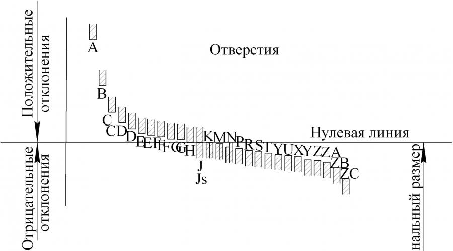
The location of the main deviations of holes and shafts is shown in Fig. 3.2.

3.3. Basic hole deviations
The main deviations of the holes are designed in such a way as to ensure the formation of fits in the shaft system, similar to fits in the hole system. The main deviations of the holes are equal in magnitude and opposite in sign to the main deviations of the shafts, denoted by the same letter (Fig. 3.3). The main deviations of holes are determined by two rules.
General rule. The main deviation of the hole must be symmetrical relative to the zero line to the main deviation of the shaft, denoted by the same letter: EI = – es for A – H; ES = – ei – for J – ZC.

The rule is valid for all deviations, except for deviations of the hole N grades 9 - 16 for sizes over 3 mm they have ES = 0 and for deviations that are subject to a special rule.
Special Rule. Two corresponding fits in the hole system and in the shaft system, in which a hole of a given quality is connected to the shaft of the next more accurate quality, must have the same clearances or interference (for example, H7/p6 and P7/h6).
A special rule applies for size intervals greater than 3 mm for holes:
J, K, M, N – up to 8th grade inclusive;
P – ZC up to 7th grade inclusive.
Writing a special rule in the form of a formula looks like:
ES = – ei + Δ, (3.13)
where Δ = IT n – IT n–1, i.e. the difference between the tolerance of the quality in question, with which this main deviation will be associated, and the tolerance of the nearest more accurate quality (Fig. 3.4).
Js has no main deviation, i.e. ES = + IT/2, and EI = – IT/2.
The second deviations are determined taking into account the tolerance:
ES = EI + TD; (3.14)
EI = ES – TD. (3.15)

3.4. Landings in the ESDP
The surfaces along which parts are connected are called boarding or mating, all other surfaces are called free or unmatched. The dimensions corresponding to these surfaces are called similarly: fit and free.
Landing called the nature of the connection of parts, determined by the size of the resulting gaps or interference. The fit determines the freedom of relative movement of the mating parts relative to each other. The type of landing is determined by the size and relative position tolerance fields of the hole and shaft. All plantings are divided into three groups: mobile, fixed and transitional.
The hole and shaft, regardless of fit and size tolerances, have the same mating size, i.e. the nominal size is the same (D = d).
Tolerance (T) size is the difference between the largest and smallest limit sizes or the absolute value of the algebraic difference between the upper and lower deviations.
Tolerance is always positive. It determines the permissible scattering field of the actual dimensions of suitable parts in a batch, i.e., the specified manufacturing accuracy. As tolerances decrease, product quality generally improves, but production costs increase.
To visually represent the dimensions, maximum deviations and tolerances, as well as the nature of the connections, use a graphical, schematic representation of the tolerance fields located relative to the zero line (Fig. 2.1).

Rice. 2.1 Tolerance fields of the hole and shaft when landing with a gap (hole deviations
are positive, shaft deviations are negative)
Zero line- this is a line corresponding to the nominal size, from which deviations of dimensions are plotted when graphic representation tolerances and landings. When the zero line is horizontal, positive deviations are laid up from it, and negative deviations are laid down.
Tolerance field
- this is a field limited by upper and lower deviations. The tolerance field is determined by the tolerance value, and its position relative to the nominal size is determined main deviation.
Main deviation
(Eo) - one of two deviations (upper or lower), determining the position of the tolerance field relative to the zero line. The main deviation is the closest distance from the boundary of the tolerance field to the zero line.
IN finished products parts in most cases are mated along their formative surfaces, forming connections. Two or more movably or stationarily connected parts are called mating. The surfaces along which the parts are connected are called mating surfaces. The remaining surfaces are called non-mating (free). In accordance with this, the sizes of mating and non-mating (free) surfaces are distinguished.
In the connection of parts included in one another, there is covering and male surfaces.
The covering surface is called hole, covered - shaft(Fig. 2.1). The terms "bore" and "shaft" refer not only to cylindrical parts. They can be applied to male and female surfaces of any shape, including non-closed ones, such as flat ones (groove and key).
Hole sizes are indicated in any capital letters, for example: A, B, G, B, C, etc., shafts - lowercase: a, b, g, b, c, etc. Limit sizes are indicated with indices max - the largest maximum size, min - the smallest maximum size, for example: A max, B min, a max, b min. The maximum deviations of the holes indicate: upper - ES, lower - EI, shafts - respectively es And ei.
When solving other problems, for example, calculating dimensional chains, maximum deviations can be designated Es- upper deviation, Ei- lower. So for the hole ES = D max - D; EI = D min - D; for shaft es = d max - d; ei = d min - d; for any size Es = A max - A; Ei = A min - A or Es = a max - a; Ei = a min - a.
The tolerances of the dimensions of the female and male surfaces are called, respectively, the hole tolerance ( TA) and shaft tolerance ( Ta).
By degrees of freedom of mutual movement The parts distinguish the following connections:
- A) motionless one-piece connections, in which one connected part is motionless relative to the other during the entire operation of the mechanism: connecting parts by welding, riveting, glue, connections with guaranteed interference (for example, a bronze rim of a worm wheel with a steel hub); the first three types of these connections are not subject to disassembly, and the fourth can be disassembled only when absolutely necessary;
- b) motionless detachable connections, differing from the previous ones in that they allow movement of one part relative to another when adjusting and disassembling the connection during repair (for example, fastening threaded, splined, keyed, wedge and pin connections);
- V) movable joints, in which one connected part moves relative to the other in certain directions during operation of the mechanism.
Each group includes many types of compounds that have their own design features and its scope. Depending on the operational requirements, connections are assembled with different landings.
Landing is the nature of the connection of parts, determined by the size of the resulting gaps or interference.
The fit characterizes greater or lesser freedom of relative movement or the degree of resistance to mutual displacement of the parts being connected. The type of fit is determined by the size and relative position of the tolerance fields of the hole and shaft. The nominal size of the hole and shaft making up the connection is general and is called the nominal fit size.
If the hole size is larger than the shaft size, then their difference is called clearance ( S), i.e. S = D - d greater than or equal to 0; if the size of the shaft before assembly is greater than the size of the hole, then their difference is called interference ( N), i.e. N = d - D> 0. In calculations, interference is taken as a negative gap.
When calculating the fits, the maximum and average clearances or interferences are determined. Largest ( S max ), smallest ( S min ) and average gap ( S m ), are equal: S max = D max - d min; S min = D min - d max ; S m = 0.5·( S max + S min). Largest ( N max ), smallest tension ( N min ) and average interference ( N m ) are equal: N max = d max - D min; N min = d min - D max ; N m = 0.5·( N max + N min).
The fits are divided into three groups: with clearance, with interference and transitional fits.
Clearance fit
- a fit that provides a gap in the connection (the tolerance field of the hole is located above the tolerance field of the shaft, Fig. 2.2, a.. Fitments with a gap also include fits in which the lower limit of the hole tolerance field coincides with the upper limit of the shaft tolerance field, i.e. .e. S min = 0.
Interference fit
- a fit that ensures interference in the connection (the tolerance field of the hole is located under the tolerance field of the shaft, Fig. 2.2, c.
Transitional fit - a fit in which it is possible to obtain both a gap and an interference fit (the tolerance fields of the hole and shaft overlap partially or completely, Fig. 2.2, b.

Fig.2.2. Schemes of landing tolerance fields: a - with a gap; b - transitional; in - with interference
Fit tolerance
- the difference between the largest and smallest permissible gaps (gap tolerance T.S. in clearance fits) or the largest and smallest permissible interference (interference tolerance TN in interference fits): T.S. = S max - S min; TN = N max - N min.
IN transitional landings the fit tolerance is equal to the sum of the largest gap and the largest interference taken according to absolute value TS(N) = S max + N max. For all types of fits, the fit tolerance is equal to the sum of the hole and shaft tolerances, i.e. TS(N) = ТD + Td.
In transitional fits, with the largest maximum shaft size and the smallest maximum hole size, the greatest interference is obtained ( N max ), and with the largest maximum hole size and the smallest maximum shaft size - the largest gap ( S max). The minimum clearance in the transition fit is zero ( S min = 0). The average clearance or interference is equal to half the difference between the maximum clearance and the maximum interference S m( N m ) = 0.5·( S max - N max). A positive value corresponds to a gap S m, negative - interference N m.
Size tolerance and tolerance range
Maximum deviations are taken taking into account the sign.
Limit deviations
To simplify dimensioning, maximum deviations are indicated in the drawings instead of maximum dimensions.
Upper deviation– algebraic difference between the largest limit and nominal sizes (Fig. 1, b):
for the hole – ES = Dmax – D ;
for the shaft – es = d max – d .
Lower deviation– algebraic difference between the smallest limit and nominal sizes (Fig. 1, b):
for the hole – EI = Dmin – D ;
for the shaft – ei = d min – d .
Since the limit sizes can be greater or less than the nominal size or one of them can be equal to the nominal size, therefore the limit deviations can be positive, negative, one of them can be positive, the other can be negative. In Fig. 1b for the hole, the upper deviation ES and lower deviation EI are positive.
Based on the nominal size and maximum deviations indicated on the working drawing of the part, the maximum dimensions are determined.
Largest size limit– algebraic sum of the nominal size and upper deviation:
for the hole – Dmax = D + ES ;
for the shaft – d max = d + es .
Smallest size limit– algebraic sum of the nominal size and lower deviation:
for the hole – Dmin = D+EI;
for the shaft – d min = d + ei.
Size tolerance ( T or IT ) – the difference between the largest and smallest limit sizes, or the value of the algebraic difference between the upper and lower deviations (Fig. 1):
for hole - T D = Dmax - Dmin or T D = ES– EI;
for shaft - Td = d max – d min or Td = es - ei .
The size tolerance is always positive. This is the interval between the largest and smallest limit sizes, in which the actual size of a suitable part element should be located.
Physically, the size tolerance determines the amount of officially permitted error that occurs during the manufacture of a part for any element.
Example 2.For hole Æ18 the lower deviation is set
EI
= + 0.016 mm, upper deviation ES
=+0.043 mm.
Determine the maximum dimensions and tolerance.
Solution:
largest limit size D max =D + ES= 18+(+0.043)=18.043 mm;
smallest size limit D min =D + EI= 18+(+0.016)=18.016 mm;
T D = D max - D min = 18.043 – 18.016 = 0.027 mm or
T D = ES - EI= (+0.043) – (+0.016) = 0.027 mm.
In this example, a size tolerance of 0.027 mm means that the good batch will contain parts whose actual dimensions may differ from each other by no more than 0.027 mm.
The smaller the tolerance, the more accurately the part element must be manufactured and the more difficult, complex and therefore more expensive it is to manufacture. The larger the tolerance, the rougher the requirements for the part element and the easier and cheaper it is to manufacture. For production, it is economically profitable to use large tolerances, but only so that the quality of the product does not decrease, so the choice of tolerance must be justified.
To better understand the relationship between nominal and maximum sizes, maximum deviations and size tolerances, perform graphical constructions. To do this, the concept of the zero line is introduced.
Zero line- a line corresponding to the nominal size, from which dimensional deviations are plotted when graphically depicting tolerance fields and fits. If the zero line is located horizontally, then positive deviations are laid up from it, and negative ones are laid down (Fig. 1, b). If the zero line is located vertically, then positive deviations are plotted to the right of the zero line. The scale for graphic constructions is chosen arbitrarily. Let's give two examples.
Example 3. Determine the maximum dimensions and size tolerance for a Ø 40 shaft and construct a diagram of the tolerance fields.
Solution:
nominal size d = 40 mm;
upper deviation es = – 0.050 mm;
lower deviation ei = – 0.066 mm;
largest limit size d max = d+es = 40 + (– 0.05) = 39.95 mm;
smallest size limit d min = d+ei = 40 + (– 0.066) = 39.934 mm;
size tolerance T d = dmax - dmin = 39.95 – 39.934 = 0.016 mm.
Example 4. Determine the maximum dimensions and size tolerance for a shaft Ø 40±0.008 and construct a diagram of the tolerance fields.
Solution:
nominal shaft diameter size d = 40 mm;
upper deviation es = + 0.008 mm;
lower deviation ei = – 0.008 mm;
largest limit size d max = d+es = 40 + (+ 0.008) = 40.008 mm;
smallest size limit d min = d+ei = 40 + (– 0.008) = 39.992 mm;
size tolerance T d = dmax - dmin = 40.008 – 39.992 = 0.016 mm.

Fig.2. Shaft tolerance diagram Ø 40


Rice. 3. Diagram of the tolerance range of the shaft Ø 40±0.008
In Fig. 2 and fig. Figure 3 shows diagrams of tolerance fields for a shaft Ø 40 and for a shaft Ø 40±0.008, from which it can be seen that the nominal size of the shaft diameter is the same d= 40 mm, size tolerance is the same Td= 0.016 mm, so the cost of manufacturing these two shafts is the same. But the tolerance fields are different: for a shaft Ø 40 tolerance Td is located below the zero line. Due to maximum deviations, the largest and smallest limit sizes are less than the nominal size ( d max = 39.95 mm, d min = 39.934 mm).
For shaft Ø 40±0.008 tolerance Td located symmetrically relative to the zero line. Due to extreme deviations, the largest limit size is larger than the nominal size ( d max = 40.008 mm,), and the smallest limit size is less than the nominal ( d min = 39.992 mm).
Thus, the tolerance for the indicated shafts is the same, but the standardized limits by which the suitability of the parts are determined are different. This happens because the tolerance fields of the shafts in question are different.
Tolerance field– this is a field limited by upper and lower deviations or maximum dimensions (Fig. 1, Fig. 2, Fig. 3). The tolerance field is determined by the size of the tolerance and its position relative to the zero line (nominal size). With the same tolerance for the same nominal size, there may be different tolerance fields (Fig. 2, Fig. 3), and therefore different standardized limits.
To produce suitable parts, it is necessary to know the tolerance field, i.e., the tolerance for the size of the part element and the location of the tolerance relative to the zero line (nominal size) are known.
3. The concepts of “shaft” and “hole”
When assembled, manufactured parts form various connections, conjugations, one of which is shown in Fig. 4.
Non-Mating
(free)
![]()
|


Rice. 4. Shaft and hole pairing
The parts that form a mate are called mating parts.
The surfaces along which the parts are mated are called mating, and the remaining surfaces are called non-mating (free).
Dimensions that relate to mating surfaces are called mating. The nominal dimensions of the mating surfaces are equal to each other.
Dimensions that relate to non-mating surfaces are called non-mating dimensions.
In mechanical engineering, the dimensions of all elements of parts, regardless of their shape, are conventionally divided into three groups: shaft dimensions, hole dimensions, and dimensions not related to shafts and holes.
Shaft– a term conventionally used to designate the external (male) elements of parts, including elements limited by flat surfaces (non-cylindrical).
Hole– a term conventionally used to designate the internal (enclosing) elements of parts, including elements limited by flat surfaces (non-cylindrical).
For mating elements of parts, based on the analysis of working and assembly drawings, the female and male surfaces of the mating parts are established, and thus, the belonging of the mating surfaces to the “shaft” and “hole” groups is established.
For non-mating elements of parts - whether they relate to a shaft or a hole - a technological principle is used: if during processing from base surface(always processed first) the size of the element increases - this is the hole; if the size of the element decreases - this is the shaft.
The group of dimensions and elements of parts not related to shafts and holes include chamfers, rounding radii, fillets, protrusions, depressions, distances between axes, planes, axis and plane, depth of blind holes, etc.
These terms were introduced for the convenience of normalizing requirements for the accuracy of surface dimensions, regardless of their shape.
The property of independently manufactured parts (or assemblies) to take their place in the assembly (or machine) without additional processing during assembly and to perform their functions in accordance with technical requirements to the operation of this unit (or machine)
Incomplete or limited interchangeability is determined by the selection or additional processing parts during assembly
Hole system
A set of fits in which different clearances and interferences are obtained by connecting different shafts to the main hole (a hole whose lower deviation is zero)
Shaft system
A set of fits in which various gaps and interferences are obtained by connecting various holes with the main shaft (shaft whose upper deviation is zero)
In order to increase the level of interchangeability of products and reduce the range of standard tools, tolerance fields for shafts and holes for preferred applications have been established.
The nature of the connection (fit) is determined by the difference in the sizes of the hole and the shaft
Terms and definitions according to GOST 25346
Size- numeric value linear magnitude(diameter, length, etc.) in selected units of measurement
Actual size— element size determined by measurement
Limit dimensions- two maximum permissible sizes of an element, between which the actual size must be (or can be equal to)
Largest (smallest) limit size- largest (smallest) permissible size element
Nominal size- the size relative to which deviations are determined
Deviation- algebraic difference between the size (actual or maximum size) and the corresponding nominal size
Actual deviation— algebraic difference between the real and the corresponding nominal sizes
Maximum deviation— algebraic difference between the limit and the corresponding nominal sizes. There are upper and lower limit deviations
Upper deviation ES, es— algebraic difference between the largest limit and the corresponding nominal dimensions
ES— upper deviation of the hole; es— upper shaft deflection
Lower deviation EI, ei— algebraic difference between the smallest limit and the corresponding nominal sizes
EI— lower deviation of the hole; ei- lower shaft deflection
Main deviation- one of two maximum deviations (upper or lower), which determines the position of the tolerance field relative to the zero line. In this system of tolerances and landings, the main deviation is that closest to the zero line
Zero line- a line corresponding to the nominal size, from which dimensional deviations are plotted when graphically depicting tolerance and fit fields. If the zero line is horizontal, then positive deviations are laid up from it, and negative deviations are laid down.
Tolerance T- the difference between the largest and smallest limit sizes or the algebraic difference between the upper and lower deviations
Admission is absolute value unsigned
IT standard approval- any of the tolerances established by this system of tolerances and landings. (Hereinafter, the term “tolerance” means “standard tolerance”)
Tolerance field- a field limited by the largest and smallest maximum dimensions and determined by the tolerance value and its position relative to the nominal size. In a graphical representation, the tolerance field is enclosed between two lines corresponding to the upper and lower deviations relative to the zero line
Quality (degree of accuracy)- a set of tolerances considered to correspond to the same level of accuracy for all nominal sizes
Tolerance unit i, I- a multiplier in tolerance formulas, which is a function of the nominal size and serves to determine the numerical value of the tolerance
i— tolerance unit for nominal dimensions up to 500 mm, I— tolerance unit for nominal dimensions St. 500 mm
Shaft- a term conventionally used to designate the external elements of parts, including non-cylindrical elements
Hole- a term conventionally used to designate the internal elements of parts, including non-cylindrical elements
Main shaft- a shaft whose upper deviation is zero
Main hole- a hole whose lower deviation is zero
Maximum (minimum) material limit- a term relating to that of the limiting dimensions to which the largest (smallest) volume of material corresponds, i.e. the largest (smallest) maximum shaft size or the smallest (largest) maximum hole size
Landing- the nature of the connection of two parts, determined by the difference in their sizes before assembly
Nominal fit size- nominal size common to the hole and shaft making up the connection
Fit tolerance- the sum of the tolerances of the hole and shaft making up the connection
Gap- the difference between the dimensions of the hole and the shaft before assembly, if the hole size is larger than the shaft size
Preload- the difference between the dimensions of the shaft and the hole before assembly, if the shaft size is larger than the hole size
The interference can be defined as the negative difference between the dimensions of the hole and the shaft
Clearance fit- a fit that always creates a gap in the connection, i.e. the smallest limit size of the hole is greater than or equal to the largest limit size of the shaft. When shown graphically, the tolerance field of the hole is located above the tolerance field of the shaft
Pressure landing - a landing in which interference is always formed in the connection, i.e. The largest maximum hole size is less than or equal to the smallest maximum shaft size. When shown graphically, the tolerance field of the hole is located below the tolerance field of the shaft
Transitional fit- a fit in which it is possible to obtain both a gap and an interference fit in the connection, depending on the actual dimensions of the hole and shaft. When graphically depicting the tolerance fields of the hole and shaft, they overlap completely or partially
Landings in the hole system
— fits in which the required clearances and interferences are obtained by combining different tolerance fields of the shafts with the tolerance field of the main hole

Fittings in the shaft system
— fits in which the required clearances and interferences are obtained by combining different tolerance fields of the holes with the tolerance field of the main shaft

Normal temperature— the tolerances and maximum deviations established in this standard refer to the dimensions of parts at a temperature of 20 degrees C
Size tolerance – is called the difference between the largest and smallest limit sizes or the algebraic difference between the upper and lower deviations /2/.
Tolerance is designated by the letter “T” (from lat. tolerance– tolerance):
TD = D max – Dmin = ES – EI – hole size tolerance;
Td = dmax - dmin = es – ei – shaft size tolerance.
For previously discussed examples 1 - 6 (section 1.1), dimensional tolerances are determined as follows:
1) Td = 24.015 – 24.002 = 0.015 – 0.002 = 0.013 mm;
2) Td = 39.975 – 39.950 = (-0.025) – (-0.050) = 0.025 mm;
3) TD = 32.007 – 31.982 = 0.007 – (-0.018) = 0.025 mm;
4) TD = 12.027 – 12 = 0.027 – 0 = 0.027 mm;
5) Td = 78 – 77.954 = 0 – (- 0.046) = 0.046 mm;
6) Td = 100.5 – 99.5 = 0.5 – (- 0.5) = 1 mm.
Tolerance – the value is always positive . The tolerance characterizes the manufacturing accuracy of the part. The smaller the tolerance, the more difficult it is to process the part, since the requirements for the accuracy of the machine, tools, devices, and worker qualifications increase. Unreasonably large tolerances reduce the reliability and quality of the product.
In some connections various combinations The maximum dimensions of the hole and shaft may cause gaps or interference. The nature of the connection of parts, determined by the size of the resulting gaps or interferences, called landing . The fit characterizes greater or lesser freedom of relative movement of the parts being connected or the degree of resistance to their mutual displacement /1/.
Distinguish three groups of landings:
1) with guaranteed clearance;
2) transitional;
3) with guaranteed interference.
If the hole dimensions more sizes shaft, a gap appears in the connection.
Gap – this is the positive difference between the dimensions of the hole and the shaft /1/:
S = D – d 0 – gap;
Smax = Dmax – dmin – largest gap,
Smin = Dmin – dmax – smallest gap.
If before assembly the dimensions of the shaft are larger than the dimensions of the hole, then interference occurs in the connection. Preload – this is the positive difference between the dimensions of the shaft and the hole /1/:
N = d – D 0 – interference,
Nmax = dmax – Dmin – maximum interference;
Nmin = dmin – Dmax – minimum tension.
Fittings in which there is a possibility of a gap or interference are called transitional.
Fit tolerance – this is the clearance tolerance for fits with guaranteed clearance (defined as the difference between the largest and smallest gaps) or the interference tolerance for fits with guaranteed interference (defined as the difference between the largest and smallest interference). In transitional fits, the fit tolerance is the clearance or interference tolerance /1/.
Fit tolerance designation:
TS = Smax – Smin – fit tolerance for fits with guaranteed clearance.
TN = Nmax – Nmin – fit tolerance for fits with guaranteed interference.
T(S,N)=Smax + Nmax – fit tolerance for transitional fits.
For any group of landings, the landing tolerance can be determined by the formula