Gas boiler aogv 9 3. Automation for gas boilers: eliminating problems with igniting the pilot. Main malfunctions of Ferroli gas boilers
Read also
From this article you will learn what problems can arise in the automation of gas boilers, why it is impossible to ignite the igniter, which is why the boiler can turn off for no reason, and most importantly, we will figure out what actions need to be taken to diagnose and eliminate this malfunction.
Owners of non-volatile gas boilers are probably familiar with the situation when, for some reason, it is not possible to ignite the boiler, or a lot of time is spent on ignition. IN in this case The problem lies in the boiler automation.
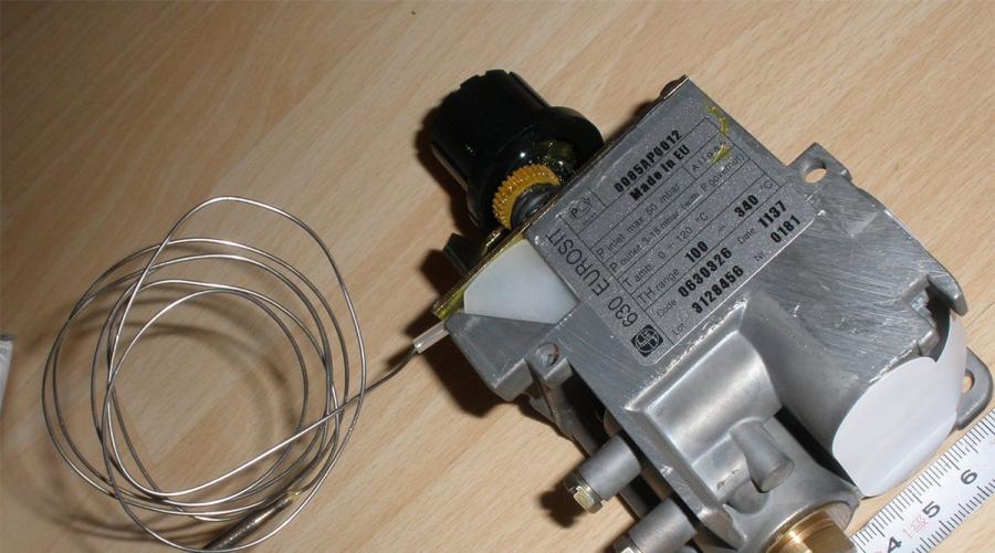
Today, it is most often used in domestic and imported gas equipment. gas valve EUROSIT 630. It is he who performs the functions of maintaining the specified coolant temperature and in the event emergency situation completely shuts off the gas supply to the burners. Further starting of boilers with such automation is only possible manually. However, the cause of a boiler emergency shutdown is not always a real accident.
Let's try to understand this using the example of the Zhitomir-3 boiler. Automatically, it provides protection against loss of flame on the igniter and loss of traction.

Note: All gas-hazardous work must be carried out exclusively by representatives of specialized organizations that have the appropriate permits. Therefore, this article is provided for informational purposes only. This article will also help you monitor the work of the technician and, perhaps, save you from the need to purchase unnecessary spare parts.
Let's decide what we will call igniting the igniter. The EUROSIT 630 valve control knob allows you to switch the boiler to three main modes:
- disabled;
- ignition;
- temperature adjustment (1-7).
To ignite the pilot burner (igniter), you must move the control knob to the “ignition” (spark) position, press it and use the piezo ignition button to ignite the pilot burner. Next, the handle is held for several seconds (no more than 30) and released. The pilot light should continue to burn. This is what we will call igniting the igniter. If the pilot light goes out, you need to repeat the procedure several more times. If this does not help, you need to look for the problem.

At the moment the igniter is ignited, the flame heats the thermocouple, which in turn generates an EMF (approximately 25 mV for working SIT thermocouples), which is supplied through the automation sensor(s) circuit to the solenoid valve.
By pressing the gas valve handle, we manually open the solenoid valve, supplying gas to the igniter, which, if proper operation equipment, is held by the EMF generated by the thermocouple and remains in the open position after the handle is released. The thermocouple itself performs the function of protecting against loss of flame on the igniter. The sensors located in the circuit are normally closed and, when triggered, open their contacts, providing complete shutdown boiler
Preparing for work
To carry out work to identify and eliminate problems with igniter ignition, we will need the following tool:
- open-end wrenches No. 9, 10, 12;
- pliers;
- multimeter;
- flathead screwdriver;
- alcohol.

Let's get started
To determine the cause of the malfunction, we will check the thermocouple circuit - solenoid valve. First, let's check the traction sensor. In this boiler it is located on the gas duct. To do this, remove two terminals from the sensor.

We close the two terminals together; they should connect tightly (to do this, you can press them a little with pliers).

We are trying to ignite the igniter. If this was possible, the cause of the malfunction is in the traction sensor. However, do not rush to change it. Let's check it first.
Note: In this work, we dismantle the sensor in order to show the features of its installation on the boiler and its markings. This is not necessary for verification.
Unscrew the two screws securing the draft sensor to the boiler flue.

Please note that the sensor is not attached tightly to the flue body, but is mounted on paronite gaskets. This is necessary in order to reduce the heating of the sensor through its contact with the body, and also to ensure a gap between the hole in the flue duct and the plane of the sensor.
We inspect the sensor. Its contacts must be firmly attached to the body. There should be no oxidation on them. The sensor rating (the temperature at which the sensor contact opens) in this case is 75 °C (designation on the housing L75C).

We check the traction sensor with a tester, measuring its resistance. It should be minimal (equal to the resistance of the probes) - 1-2 Ohms. If the sensor does not ring, it is clearly necessary to replace it with a similar one (with the appropriate response temperature).

If the sensor was able to ring, wipe the contacts of the sensor and the circuit terminals with alcohol, tighten them with pliers and dry them. We mount the sensor in place and connect it. We are trying to ignite.

If ignition was successful, the cause of the malfunction has been found and eliminated.
Be sure to check the draft after igniting the main burner. To do this, you can bring your hand to the place where the traction sensor is installed. No heat should come out of this hole. If this happens, it is necessary to eliminate the cause causing insufficient traction. In this case, the sensor works correctly.
Attention! Operating a boiler with a faulty chimney is strictly prohibited!
We remove the terminals from the contacts of the traction breaker and measure the resistance of the circuit. It should be no more than 3 ohms.

If this condition is met, we perform the following actions. Using wrench No. 9, unscrew the nut securing the thermocouple to the traction breaker. Using wrench No. 12, unscrew the traction breaker, which consists of two parts: a brass sleeve and a plastic insert, by half a turn.

We take out the plastic insert with contacts and unscrew the part completely.

Checking the thermocouple. We connect it directly to the solenoid valve (the place where the traction breaker was installed). We fix it with key No. 9.

We ignite the igniter. If it fails, the cause of the malfunction is most likely in the thermocouple. Solenoid valve It rarely fails.
Let's examine the thermocouple. In some cases, the thermocouple can be repaired. It happens that the thermocouple contact disappears. This is not a reason to replace it, just solder it.

It is important that the dielectric gasket is intact.

Make sure the thermocouple is positioned correctly in the pilot flame. The tip of the thermocouple should be immersed in the flame.

To adjust the position of the thermocouple relative to the igniter flame, use a No. 10 wrench to loosen the nut securing the thermocouple to the pilot burner. When moving the thermocouple, it is necessary to install it in the correct position and fix it with key No. 10.

To make a final verdict on replacement, you can measure the EMF generated by the thermocouple. To do this, it is necessary to ignite the igniter, and, holding the valve handle pressed, measure the EMF between the thermocouple contact and its body. The optimal value should be at least 18 mV. If the thermocouple is working, clean the parts of the traction breaker with alcohol, and also wipe the contact of the thermocouple. Especially if it had to be soldered.

We assemble the traction breaker in the reverse order and connect a thermocouple to it. The parts should not be pressed too hard. The force must be sufficient to ensure reliable contact. We crimp the terminals with pliers and, after wiping them with alcohol, try to ignite.

Performing all the above steps will surely help you troubleshoot your boiler.
Another cause of problems with ignition may be insufficient gas pressure on the igniter. This occurs due to a clogged nozzle. To clean it, you need to use a No. 10 wrench to loosen the fastening nut. copper tube igniter and remove the nozzle.
Advice: You can lightly tap the igniter to make it easier to remove the nozzle.

Cleaning the hole in the main jet copper wire. Violation of the hole size is not allowed!

At moments of the most intense gas consumption, the pressure in the central main pipe may drop. Accordingly, the gas pressure at the igniter may also decrease. This may require adjusting the gas pressure at the igniter. Unscrew the screw securing the decorative trim and remove it.

The adjustment is made by turning the screw on the valve. When turning it counterclockwise, the gas pressure on the igniter increases.

These tips will help you deal with problems with ignition of your boiler. In practice, the most common problems are with the contacts, and not with the sensors. Therefore, if each time you ignite the igniter you have to hold the valve handle longer and longer, we advise you to simply clean the contacts and tighten the automation terminals. In order to avoid real problems with the operation of the automation, we recommend cleaning the boiler in a timely manner.
Gasification has been progressing at a fairly rapid pace lately. settlements Russia. The main element of equipment that is installed in every rural house is a gas boiler with its experience in repairing automatic equipment, popular in rural areas gas boiler AOGV - 17.4-3 produced by the Zhukovsky Mechanical Plant is shared by the author of this material.
Purpose and description of the main components of the AOGV - 17.3-3.
Appearance heating gas boiler AOGV - 17.3-3 is shown on rice. 1, and its main parameters are given in the table.
| Parameter | Meaning |
| Dimensions (H×W×D), mm | 1050×420×480 |
| Weight, kg | 49 |
| Nominal thermal power, kW | 17,4 |
| Heated area, m 2 (no more) | 140 |
| Type of fuel | natural / liquefied gas |
| Fuel consumption, m 3 /h, (kg/h) | 1,87 (1,3) |
| Hot water consumption at 35 o C | 5,4 |
| Chimney diameter, mm | 135 |
| Nominal gas pressure, Pa | 1274 |
| Minimum gas pressure, Pa | 635 |
| Removal of combustion products | natural craving |
| Burner type | atmospheric |
| Heat exchanger material | steel |
| Type of installation | floor |
| Automation type | electrically independent |
Construction of a gas boiler AOGV - 17.3-3
Its main elements are shown in rice. 2 . The numbers in the figure indicate: 1 - draft breaker; 2 - traction sensor; 3 - traction sensor wire; 4 -start button; 5 -door; 6 -gas magnetic valve; 7 -adjusting nut; 8 -tap; 9 -storage tank; 10 -burner; 11 -thermocouple; 12 - igniter; 13 - thermostat; 14 -base; 15 - water supply pipe; 16 - heat exchanger; 17 -turbulator; 18 - bellows unit; 19 - water drainage pipe; 20 - traction breaker door; 21 -thermometer; 22 -filter; 23 -cap.
The boiler is made in the form of a cylindrical tank. On the front side there are controls that are covered with a protective cover. Gas valve 6 (Fig. 2) consists of an electromagnet and a valve. The valve serves to control the gas supply to the igniter and burner. In the event of an emergency, the valve automatically turns off the gas. Traction breaker 1 serves to automatically maintain the vacuum value in the boiler furnace when measuring the draft in the chimney. For normal operation the door 20 should rotate freely on the axis without jamming. Thermostat 13 designed to maintain a constant temperature of water in the tank.
The automation device is shown in rice. 3 . Let us dwell in more detail on the meaning of its elements. Gas passing through a cleaning filter 2, 9 (Fig. 3) goes to the solenoid gas valve 1 . To the valve using union nuts 3, 5 draft temperature sensors are connected. The igniter is ignited when the start button is pressed 4 . There is a setting scale on the body of thermostat 6 9 . Its divisions are graduated in degrees Celsius.
The desired water temperature in the boiler is set by the user using the adjusting nut 10 . Rotation of the nut leads to linear movement of the bellows 11 and rod 7 . The thermostat consists of a bellows-thermal bulb assembly installed inside the tank, as well as a system of levers and valves located in the thermostat housing. When the water is heated to the temperature indicated on the dial, the thermostat is activated and the gas supply to the burner is stopped, while the igniter continues to operate. When the water in the boiler has cooled down to 10 ... 15 degrees, the gas supply will resume. The burner lights up from the pilot flame. While the boiler is operating, it is strictly forbidden to regulate (reduce) the temperature with the nut 10 - this may cause the bellows to break. The temperature on the dial can be reduced only after the water in the tank has cooled to 30 degrees. It is prohibited to set the temperature on the sensor above 90 degrees - this will trigger the automation device and turn off the gas supply. The appearance of the thermostat is shown in (Fig. 4) .

How does the AOGV gas boiler turn on?
Actually, the procedure for turning on the device is quite simple, and besides, it is described in the operating instructions. And yet, let’s consider a similar operation with a few comments:
— open the gas supply valve (the valve handle should be directed along the pipe);
- press and hold the start button. In the lower part of the boiler, a hissing of escaping gas will be heard from the igniter nozzle. Then light the igniter and after 40...60 and release the button. A similar time delay is necessary to warm up the thermocouple. If the boiler has not been used for a long time, the pilot light should be lit 20...30 s after pressing the start button. During this time, the igniter will fill with gas, displacing the air.
Possible malfunctions of the AOGV gas boiler
After releasing the start button, the igniter goes out. A similar defect is associated with a malfunction of the boiler automation system. Please note that operating the boiler with the automation switched off (for example, if the start button is forcibly jammed while pressed) is strictly prohibited. This can lead to tragic consequences, since if the gas supply is briefly interrupted or if the flame is extinguished by a strong air flow, gas will begin to flow into the room.
To understand the reasons for the occurrence of such a defect, let’s take a closer look at the operation of the automation system. In Fig. Figure 5 shows a simplified diagram of this system.
The circuit consists of an electromagnet, a valve, a draft sensor and a thermocouple. To turn on the igniter, press the start button. The rod connected to the button presses on the valve membrane, and gas begins to flow to the igniter. After this, the igniter is lit.
The pilot flame touches the body of the temperature sensor (thermocouple). After some time (30...40 s), the thermocouple heats up and an EMF appears at its terminals, which is sufficient to trigger the electromagnet. The latter, in turn, fixes the rod in the lower (as in Fig. 5) position. The start button can now be released.

The traction sensor consists of bi metal plate and contact (Fig. 6). The sensor is located in the upper part of the boiler, near the pipe for exhausting combustion products into the atmosphere. If a pipe is clogged, its temperature rises sharply. The bimetallic plate heats up and breaks the voltage supply circuit to the electromagnet - the rod is no longer held by the electromagnet, the valve closes and the gas supply stops.

The location of the automation device elements is shown in Fig. 7. It shows that the electromagnet is covered with a protective cap. The wires from the sensors are located inside thin-walled tubes. The tubes are attached to the electromagnet using union nuts. The body terminals of the sensors are connected to the electromagnet through the housing of the tubes themselves.

Let's consider the method for finding the above fault.
Check during gas boiler repair they start with the “weakest link” of the automation device - the traction sensor. The sensor is not protected by a casing, so after 6...12 months of operation it becomes “overgrown” with a thick layer of dust. Bimetallic plate (see Fig. 6) oxidizes quickly, which leads to poor contact.
The dust coat is removed with a soft brush. Then the plate is pulled away from the contact and cleaned with fine sandpaper. We should not forget that it is necessary to clean the contact itself. Good results cleaning of these elements with a special spray “Contact” gives. It contains substances that actively destroy the oxide film. After cleaning, apply to the plate and contact thin layer liquid lubricant.
The next step is to check the serviceability of the thermocouple. She works hard thermal mode, since it is constantly in the igniter flame, naturally, its service life is significantly less than the other elements of the boiler.
The main defect of a thermocouple is burnout (destruction) of its body. In this case, the transition resistance at the welding site (junction) increases sharply. As a result, the current in the Thermocouple - Electromagnet circuit.
The bimetallic plate will be below the nominal value, which leads to the fact that the electromagnet will no longer be able to fix the rod (Fig. 5)
.
How to check the thermocouple of an AOGV boiler
To check the thermocouple, unscrew the union nut (Fig. 7) located on the left side of the electromagnet. Then turn on the igniter and use a voltmeter to measure the constant voltage (thermo-EMF) at the thermocouple contacts (Fig. 8) . A heated, serviceable thermocouple generates an EMF of about 25...30 mV. If this value is less, the thermocouple is faulty. To final check it, disconnect the tube from the electromagnet casing and measure the resistance of the thermocouple. The resistance of the heated thermocouple is less than 1 Ohm. If the resistance of the thermocouple is hundreds of Ohms or more, it must be replaced. The appearance of a thermocouple that failed as a result of burnout is shown in rice. 9 . The price of a new thermocouple (complete with tube and nut) is about 300 rubles. It is better to purchase them in the store at the manufacturer or use the services of an authorized service center. The fact is that the manufacturer is constantly improving its products. This is reflected in the parameters of the parts self-made. For example, in the AOGV-17.4-3 boiler of the Zhukovsky plant, starting from 1996, the length of the thermocouple connection has been increased by approximately 5 cm (that is, similar parts produced before or after 1996 are not interchangeable). This kind of information can only be obtained from a store (authorized service center).

A low value of thermo-EMF generated by a thermocouple can be caused by the following reasons:
— clogging of the igniter nozzle (as a result of this, the heating temperature of the thermocouple may be lower than the nominal one). They “treat” such a defect by cleaning the igniter hole of any soft wire suitable diameter;
— shifting the position of the thermocouple (naturally, it may also not heat up enough). Eliminate the defect as follows - loosen the screw securing the liner near the igniter and adjust the position of the thermocouple (Figure 10);
- low gas pressure at the boiler inlet.
If the EMF at the thermocouple terminals is normal (while the symptoms of malfunction indicated above remain), then check the following elements:
— integrity of contacts at the connection points of the thermocouple and draft sensor.
Oxidized contacts must be cleaned. The union nuts are tightened, as they say, “by hand.” In this case wrench It is not advisable to use it, since you can easily break the wires suitable for the contacts;
- integrity of the electromagnet winding and, if necessary, solder its terminals.
The functionality of the electromagnet can be checked as follows. Disconnect the thermocouple line. Press and hold the start button, then light the igniter. From a separate DC voltage source, a voltage of about 1 V is applied to the released electromagnet contact (from a thermocouple) relative to the housing (at a current of up to 2 A). For this you can use regular battery(1.5 V), the main thing is that it provides the necessary operating current. The button can now be released. If the igniter does not go out, the electromagnet and draft sensor are working;
- traction sensor
First, check the force of pressing the contact against the bimetallic plate (with the indicated signs of malfunction, it is often insufficient). To increase the clamping force, release the lock nut and move the contact closer to the plate, then tighten the nut. In this case, no additional adjustments are required - the clamping force does not affect the response temperature of the sensor. The sensor has large stock according to the angle of deflection of the plate, ensuring reliable tearing electrical circuit in case of an accident.
It is not possible to light the igniter - the flame flares up and immediately goes out.
There may be the following possible reasons similar defect:
- closed or faulty gas tap at the boiler inlet,
— the hole in the igniter nozzle is clogged, in this case it is enough to clean the nozzle hole with soft wire;
— the igniter flame is blown out due to strong air draft;
The gas supply is turned off when the boiler is running:
- the draft sensor is triggered due to a clogged chimney, in this case it is necessary to check and clean the chimney;
— the electromagnet is faulty, in this case the electromagnet is checked according to the above method;
- low gas pressure at the boiler inlet.
The writing of this publication was prompted by a chain of events that forced me to try my hand at self-service gas boiler. Let me note right away that this is not quite an “exchange of best practices”, as it is usually presented, since some of the facts presented speak, on the contrary, about the initial complete inexperience of the user. But perhaps the information presented will help those who read it avoid such mistakes.
The fact is that with the seeming abundance of information on the Internet, I had to face the fact that there are no intelligible step by step instructions It’s not so easy to find - most often everything is limited to selective advice on forums. The factory instruction manual covers many problems rather dryly and does not provide much clarity, and some important aspects in general, it is practically omitted, which, in principle, led to the situation that will be discussed. So, what caused and how did you clean the gas boiler AOGV-11.6-3 with your own hands?
How it all began
B purchased own house we moved in in September 2002. The heating system was (and remains), but then it was organized according to the principle natural circulation. The boiler room is in a separate extension, equipped in accordance with all existing rules. An old cast iron boiler with gas burners, some, as I remember now, incredible large sizes, also with “home-made” fireclay brick masonry inside. It was complete ruin: every month in our not-so-cold winters (Moldova, Transnistria) the meter added 800 cubic meters!
In a word, it was decided to carry out a replacement. We chose the AOGV-11.6-3-U, both for reasons of low cost and taking into account the weight good reviews about this model from friends. At the same time, it was installed circulation pump. The results were not long in coming - the next winter the house was much more comfortable, and the heat was distributed evenly throughout all rooms. And monthly gas consumption has dropped by more than three times! – we usually fit in 220 – 270 cubic meters.
Prices for gas boiler AOGV-11.6-3
gas boiler AOGV-11.6-3

To the credit of the manufacturers, it must be said right away that over the past 13 years there have been absolutely no problems with the operation of these purchased devices. Even in cold winter 2008-2009, when another “gas war” was going on, and the pressure in the gas supply pipes was reduced to a critical minimum, the boiler coped with the task quite well - the house was not hot, and we were not in danger of freezing. To be honest, it was even strange for me to read on the forums that many people at home have the gas valve button permanently connected to these ones - no problems with the automation have simply appeared during the entire period of operation.
Inspector visits gas industry in our city they are held regularly. There have never been any particular complaints about the operation of the equipment. The only remark was the year before last - to replace the corrugated section of the chimney (before inserting into the main pipe) with one made of galvanized steel. The deficiency has been corrected.
This year the cold snap came a little early, and already at the beginning of October it was decided to start the boiler at the very minimum power. But a problem emerged - the igniter wick did not want to light up, and if it did, it was with such a tiny flame that it was barely visible. Naturally, such a torch did not provide heating for the thermocouple, and the automation did not work.
A similar situation (but on a smaller scale: the torch lit up immediately, but was weak) was observed a year earlier. The igniter nozzle was clearly clogged, and last year it helped that I (at my own risk) managed to spray this “jet” with a can of carburetor cleaning fluid through a long curved tube. After the liquid had evaporated, I tried to light it - everything worked, and last winter, throughout the whole heating season There were no more problems.
 Last year we managed to do without any disassembly - the nozzle was cleared of such carburetor fluid
 But this year, such a measure turned out to be insufficient - the effect was even the opposite. The igniter stopped lighting altogether.
I really didn’t want to completely remove the entire gas assembly with burners (and at that time I didn’t even know how accessible it was). I tried unscrewing the gas supply tube to the igniter from the magnetic valve block and blowing it out using a car pump. Useless. There was nothing to do - I had to think about how to remove the entire burner block in order to mechanically clean the igniter nozzle.
The boiler is, of course, tied up, the system is full. Access from below is minimal, since the boiler is still standing in a special pit. All this was very scary at first - how to dismantle it? gas unit? I didn’t find any sensible advice, but I came across a hint on one of the forums - this node rotates relative to central axis– input gas pipe.
Since operations of any significant scale were not expected, I did not take photos at that stage. The operations shown below were carried out later, when the boiler was disassembled again. But the essence remains the same.
- So, if you try to look at the boiler from below (for the initial examination of the “situation” I initially used a mirror placed underneath), something like this appears:

The burner block itself is mounted on the bottom cover. Arrow pos. Figure 1 shows the entrance of the gas supply pipe to the main burner. Pos. 2 is the input of the igniter and thermocouple tubes. And this entire assembly, in addition to the rigidity of the gas pipe, is held on the flange of the cylindrical casing of the boiler by three hooks. They are located along the edge of the bottom plate on the tops regular triangle. The blue arrow shows one of them, the one located slightly to the left of the ignition window.

The second hook is closer to the back of the boiler on the left (if you stand facing the ignition window).
The third is almost exactly under the automation unit, at the level of the vertical tubes going down to the pan.
Prices for gas boilers
a gas boiler

- After a thorough inspection of the entire bottom part, I did not find any other fastening or fixing elements. This means that there must be grooves through which these protrusions can be removed from engagement with the casing flange. As a result, it turned out that there is only one groove, and it is located in the area of the third hook (as shown). To get to it, the pallet must be turned slightly clockwise. In the illustration, the direction of rotation is shown with a green arrow. By the way, the opening unpainted section of the casing is also clearly visible - you can see how the pan moves.
- I figured out the principle of fastening. But in order to rotate the pan and remove the burner block, naturally, it is necessary to disconnect the gas pipe, igniter tube and thermocouple contact tube from the automation unit.
- First of all, I checked again whether the gas supply from the home wiring was shut off.

- Then he carefully unscrewed the nuts on the fittings of the automation unit.

1 – gas supply tube to the igniter torch. Key for 12.
2 – tube with thermocouple contact. Key for 12.
3 – gas supply pipe to the main burner. The key is 27.
The paronite gasket on the main gas pipe was removed. Checked it - excellent condition. On the flare tube - the gasket remained on the tee fitting, but also - it is clear that it is not worn out, and will still serve quite well.
- After disassembling this unit, the pan turned quite easily, and through the groove closest to the tubes, the holder came out of engagement with the casing. Now, supporting the pallet from below, we slightly push it towards ourselves - and the other two holders also come out of engagement. We lower the entire assembly to the floor, and then carefully take it out between the legs of the boiler.

The photo shows the removed pan, but I’ll make a reservation once again - the photos were taken later, during the secondary disassembly of the boiler. The first time the picture was much “cleaner”. Further, in the text it will be clear why so much attention is paid to this.
- I checked the condition of the main burner - it was completely clean, without any traces of any deformation. There were no complaints about her work.
- Then he moved on to the “culprit” of this whole undertaking - the ignition torch nozzle. I unscrewed the two screws holding this assembly (wick plus thermocouple) in the assembled position. The screws, however, resisted at first, but after treatment with WD-40 they still worked. I removed the box-shaped casing from the pilot burner and got to the nozzle.
The brass nozzle itself was covered on top with a light white coating (like scale), and this was removed very quickly, without effort, with fine sandpaper. The nozzle itself, yes, was overgrown, barely “drawn” even visually. It’s also okay - I took a thin copper strand from the loose cable and cleaned the hole. To guarantee, I also blew it under pressure with a pump from the side connecting the tube to the tee of the automation unit. All task completed!
- At the same time, while there is free access, I very carefully cleaned the bend of the thermocouple tube with “zero” sandpaper: there was a very light layer of oxide there - it had accumulated during the summer period of inactivity.
- I carefully reassembled all the components in the reverse order. I struggled a bit with reinstalling the pallet, but then I got the hang of it.
You must first progressively, without distortion, lift this entire block so that the burner goes inside the housing, and the igniter and thermocouple assembly does not cling to the casing flange. Then, standing on the side of the pipes, slightly push this entire assembly towards you, give a slight downward tilt so that the opposite edge of the pan rises slightly (literally a couple of degrees!). Then, when moving the pallet forward, you should simultaneously put on two distant hooks so that they fit onto the casing flange. Direct the hook closest to you into the cut-out groove, and when it fits into it, turn the entire pallet counterclockwise. The magnitude of this rotation will be visually indicated by the position of the pipes - the gas pipe will be directly under its branch pipe of the automation unit, as it was during disassembly.
- I installed all the tubes in place, first checking the presence and correct fit of the gaskets. Tightened the nuts on the gas supply pipe and on the igniter tube with a wrench. Before reinstalling the thermocouple tube, I very carefully, literally barely touching it, cleaned the contact pads with a “null” pad. This nut, in accordance with the recommendations I read, was tightened not with a wrench, but by hand, using only finger force.
- I checked the tightness of the connections - I brought a sponge from the kitchen with detergent, opened the gas supply, “washed” the joints of the gas pipes - everything is fine, there are no signs of leakage.
- I tried to start the boiler. The wick lit up perfectly - with an even flame, “washing” the bend of the thermocouple. Literally after 15-20 seconds the gas valve activated. I waited a couple of minutes, then turned on the gas supply to the main burner - it burned smoothly, without a pop. I experimented - I closed and opened the supply to the main burner several times: everything is fine - the wick burns evenly, does not go out, the burner ignites just as normally.
That's it, I set approximately the desired heating level, closed the flap on the ignition window, and left, full of pride for the job successfully done.
Little did I know then that my “adventures” were just beginning!
Find out by studying the main evaluation criteria in a special article on our portal.
Unexpected problem
For several days the operation of the boiler did not cause any complaints - it did not go out, the heating system worked well. However, about a week passed, and it seemed to me that a previously unusual smell had appeared in the boiler room - this was not the smell of gas in pure form, but rather the “aroma” of burnt gas. In addition, the impression began to develop that, according to the feelings of those at home, there was a lack of warmth.
A couple of times the boiler went out at night - without any visible reasons. Well, then - more. About a week later, when I entered the boiler room, I saw an eerie picture - the burner flame was trying to “get out” through the ignition window covered with a shield. A fairly large section of the metal casing above the window was almost red-hot, the paint on it was completely burnt down to “pure” metal.

Naturally, the boiler was immediately extinguished. After it cooled down, I tried, as an experiment, to ignite it. The wick works fine, the automation also works well. But when the main burner is ignited, then, firstly, the flame has pronounced orange ends of the flames. And secondly, the “crown” of the flame is not directed completely upward, but also tends into the gap between the heat exchanger and the outer casing of the boiler.
It’s clear - this is a clear sign that the flow of hot gases inside the boiler encounters some kind of resistance, in a word - the channels are overgrown with soot. There is soot everywhere, even on the edge of the ignition window - I have never had my hands get dirty when igniting, but now black spots appear on my fingers, which, by the way, are very difficult to wash off even warm water with soap.
But the question remains unclear - why? After all, in so many years we have never encountered such a problem.
I went back to the forums to look for the reason. And on one of them I came across useful advice- this picture is typical incomplete combustion gas, without supplying additional air. I began to understand more closely the design of my boiler, and discovered something that I simply had not paid attention to before. This is a clamp-shaped valve at the entrance of the gas pipe to the boiler, from below, right at the pan. There on the pipe there are two diametrically opposite holes, which are covered by this damper.

I ran to check: it’s true – the damper almost completely covers both holes. Poor knowledge of the “material parts” led to the fact that I completely did not pay attention to this nuance. And in the process of disassembling the burner block, apparently, he accidentally moved this damper to a position in which the air supply was blocked.
I tried to open these windows and ignite the boiler - yes, the flame immediately changed color and became more even. But the “crown”, naturally, still tends to the space between the casing and the heat exchanger, that is, the reason found does not save me from cleaning the boiler.
Cleaning the boiler
It is clear that to carry out cleaning I need to disassemble again - also dismantle the burner block, and plus, remove the top cover of the boiler.
- I had to struggle a bit with removing the umbrella that goes into the metal part of the chimney. The fact is that the boiler room itself is made of brick, of the original type, installed on a foundation, and two pipes are built into it - from the boiler and, higher up, from the gas water heater.


I embedded the boiler pipe myself, did it well in due time, and it “fits” very tightly. I had to make an effort to achieve a slight backlash. But in the end it worked - we managed to lift it enough to have enough clearance to remove the umbrella from the pipe. The picture that emerged was very colorful.

Deposits of soot are visible under the umbrella itself. And if you look at the umbrella from below, then on the hemispherical divider-condensate collector there is a soft, loose layer of soot about 10 millimeters thick.


- To remove the top cover of the boiler, you must first disconnect and dismantle the draft sensor. It is held on the lid by plates, which are screwed with two self-tapping screws (shown by blue arrows in the illustration above). But no matter how much I twisted these screws, they turned in place without moving upward even a millimeter. In the end, I gave up on the matter and decided to remove the cover along with the sensor. To do this, first use a 14mm wrench to unscrew the nut connecting the tube to the tee of the automation unit.

I immediately checked the paronite gasket - it was “alive”, remained in place, and therefore decided not to disturb it.

- Then, it would seem, everything is simple - the lid is fixed to the boiler casing with three self-tapping screws.

The self-tapping screw, which is located on the front side of the boiler, came out quite easily.

But the other two showed “fierce resistance.” They simply did not want to budge. Neither powerful screwdrivers, nor WD-40 treatment, nor tapping helped - they stood motionless.

In the end, the slots for the screwdriver began to “lick” - but still with the same zero result. There was only one way out - to cut off the heads of the screws with a grinder, fortunately, they were not made “under countersunk”.
Prices for self-tapping screws
self-tapping screws

No problem - I cut it very carefully. Looking ahead, I will say that I subsequently replaced these mounts with roofing screws with a hexagon head - in case of future boiler cleaning. It holds even better, and unscrewing it won’t be a problem.
- The lid fit tightly, and I even had to tap it a little from below - resting a wooden block against the lower edge. After that she took off smoothly.

On the back of the lid there are clearly visible marks that were left due to improper passage of combustion products. They found their way between the heat exchanger and the boiler casing, then converging towards the central opening of the chimney.

Naturally, there is no need to talk about any efficiency of the boiler in such a situation - it rather heated the boiler room rather than giving off heat to the system. It is better to remain silent about the safety of such functioning.
- The water heat exchanger of the boiler is covered with a lid on top. It is fixed and pressed tightly to it using special fasteners - metal wedges (they are shown in the illustration above with yellow arrows). These fasteners are very easy to remove.

I thought they were spring - nothing like that. These wedges are made from ordinary mild steel, and their antennae are curved according to the same principle as ordinary cotter pins. They are easily brought to the center, and then the wedge is removed from the slot.

- In the same way, removed all the stoppers and then removed the cover. And I was horrified...

This small gap between the heat exchanger and the lid, in which gas flows from three channels must be combined into one central one to exit into the chimney, is tightly clogged with soot.
- Now it is necessary to remove the gas flow turbulator inserts from the heat exchanger channels. They gave way up without much resistance when I picked them up with pliers.

The picture turned out even worse than I could have imagined - the layer of soot on the turbulator blades is impressively thick!

At the same time, I immediately look at the condition of these vertical cylindrical channels. The picture matches...

Naturally, even if we “bracket out” the draft problems, there is no question of any efficiency of the boiler operation with the heat exchanger so overgrown on the outside.
- Next, I removed the boiler pan with the burner block - I have already described how this operation is performed above.

- That's it, you can proceed directly to cleaning all nodes. For this operation, an ordinary plastic brush for bottles was purchased from a hardware store - it will be suitable for vertical channels. Tied it with duct tape wooden slats to go through the channels along their entire height.
 I know that the “classic” for home crafts is blue electrical tape, but I only had white :)
 And to clean other parts and surfaces, I purchased a flat brush with soft brass bristles.

- I start cleaning from the top plane of the heat exchanger - I clean and sweep down all the soot deposits. It turned out as shown in the illustration above.
- Then I move on to cleaning the channels. The soot comes off the walls quite easily - it has not yet had time to “harden”. Characteristically, it is very oily.


- After cleaning the boiler itself, I move on to the removed parts and assemblies. In order not to breed excess dirt in the boiler room, I transfer all this action to the yard.


The burner itself was clean this time too, except for the soot that attacked from above - it was easily brushed off. At the same time, I immediately lightly clean the thermocouple tube with a “zero” - it won’t hurt.

- After completing the cleaning operation, I proceed to reassembling the boiler. First, I installed the burner block in place - this has already been discussed above. I immediately connected all the tubes, checked the gaskets and tightened the nuts.
And here I immediately focused my attention on the position of the valve air channel. When cleaning, I removed this clamp from the pipe (I don’t know why, though), but when reverse installation It turned out that it was made of mild steel and did not have any springing qualities. After installation, it began to dangle and simply slide down. I had to make a small improvement - drill holes in the “ears”, and after putting the flap on, tighten it slightly with a long M5 screw. It turned out fine - now the clamp is securely held in the given position, but moving it is not difficult.

The illustration shows that the air holes are half open.
- The next step is to put the turbulators in place.

Installation of turbulators is very simple, and it is simply impossible to make a mistake here - they are inserted into the channels and held in them due to the widening of the central metal plate located on top. I insert them so that this plate is oriented along the radius of the cylindrical heat exchanger, that is, the blades will be located approximately tangential to the circle.


- The next step is to replace the heat exchanger cover. The lugs for the clamps fit into the slots in the cover.

I insert metal cotter pins into the eyelet slots and lightly tap them from the back so that the lid fits as tightly as possible to the heat exchanger. After that, I spread the antennae with pliers - that’s it, the lid is securely fastened.

- Next, I replace the top cover of the boiler. Get your bearings with her correct position The holes from the only self-tapping screw that came out normally help. In my case, the traction sensor was not removed - it is already in place, and all that remains is to connect its tube to the tee and tighten the nut.

- I complete the assembly by installing the cap. I slip it under the pipe, put it on its socket (it fits very tightly), and then carefully put it in place. The three protrusions on the cap should fit into the corresponding holes in the boiler lid, and the cut out semicircular window will be placed above the passing temperature sensor tube.

- Naturally, after this all connections were checked for leaks.
- I move on to the long-awaited moment - starting the boiler. The wick caught fire immediately, and within 15 seconds the magnetic valve activated. So far so good.
I open the gas supply - the burner ignites easily, the fire burns with an even crown, with the same height of the flames, and they do not look to the sides, but are directed clearly upward, which is what needed to be proven!

- I tried to “play” with the air damper. As a result, I had to open it a little more - I achieved an even blue flame, practically without any admixtures of red or orange tints. The experimental shutdown and gas supply (simulation of boiler shutdowns and starts) was successful - the pilot flame is stable, and the burner lights up immediately and almost silently.

Two weeks have passed since then - there have been no complaints about the operation of the boiler! Winter is ahead, and I hope that the heating system will not give us any unpleasant surprises.
And for myself I decided the following:
- Be more attentive to the details of any design - everything has its purpose, and ill-considered actions can lead to emergency situations.
- The cleaning process has been mastered, it is not so complicated, so I will carry it out regularly - before the start of each heating season, at least for prevention.
Find out how to produce by studying the mandatory requirements in a special article on our portal.
The author is aware that such work, in general, should be carried out by appropriate specialists. Therefore, this article should not be regarded as a guide to action, but only as a narrative about what happened - about how one very small mistake, inattention, led to serious problems and demanded their urgent removal. I hope that the information received will be useful to someone.