Addressable fire alarm device, fire loop, what is it? Measuring insulation resistance and resistance of an alarm loop during maintenance of a security and fire alarm system. What is a loop in a security alarm system?
Read also
Let's figure out what an alarm loop (AL) is and how to organize it correctly. Let's start with the fact that the security loop is a connecting line (electrical circuit) that unites various sensors alarms (DS) or detectors - in the context of this article these are synonyms.
In addition, the loop contains a terminal device (OU), which coordinates it with control panel(PKP).
The terminal device can be:
- resistors;
- capacitors;
- diodes.
What exactly is installed at the end of the loop depends on the specific control panel model. It is worth noting that in systems burglar alarm resistors are most often used, so we will focus on this option. The structural diagram of the loop is shown in Figure 1.
I drew everything at once possible types sensors, we will now consider their operation, but in a real situation, as a rule, one connection option and detectors with the same tactics for generating an alarm notification are used.
Combinations are also possible various connections, but they are quite rare. Now let's move on to consider the main types of loops and the principle of their operation.
Attention! The numbering of loop types in this article is arbitrary. Moreover, each manufacturer can put its own interpretation into the concept of AL type. Be sure to keep this in mind!
TYPES OF SIGNALING LINES
1. AL with sensors that operate “to open”.
A very common option in security alarms. When the detector is triggered electrical circuit breaks, the current in the loop drops to zero. The same thing will happen if there is no power to the detector. But if the sensor malfunctions, there are two options:
- the contacts will open;
- will remain closed even if an intruder is detected.
In the first case, everything is clear and simple - the device will work and the malfunction will thus make itself known. The second option is dangerous because it can only be detected by fully checking the functionality of the sensor, which no one does every day. The only consolation is that such cases are rare, but, nevertheless, they do happen.
2. AL with a sensor that operates on “short circuit”.
The only difference from the first option is in the connection diagram and the fact that when triggered, the loop is closed. It is rarely used in security alarms, at least I have not encountered this method.
3. Using a detector with loop power.
Although not often, such sensors are used. If in the first two cases the voltage is supplied via a separate line, then here the detector operates from the voltage supplied to the alarm loop by the control panel. In this case, the alarm signal is generated by an increase in DC current consumption, which is monitored by the control panel.
In this case, the number of connected sensors can be limited to a few pieces. The specific value for their various types must be indicated in the passport of the security device (as well as the possibility of using this option).
4. Addressable alarm loop.
If so far we have considered cases when current control of the loop was carried out, then when using addressable detectors information about their condition is transmitted digitally. Accordingly, the information content of the alarm system increases. The DS can diagnose its condition and transmit it to the control panel.
PARAMETERS AND FAULTS
Since the security alarm loop is an electrical circuit, it is characterized by such electrical parameters as current, voltage and resistance. Moreover, the first two are secondary, and the performance of the AL depends on the resistance, which determines its three main states:
- "norm";
- "break";
- "closure".
The normal resistance of the loop should, as a rule, not exceed 1 kOhm, without taking into account the size of the terminal resistor.
It is worth explaining a little the principle of operation of the PKP-ShS-OU combination.
The device supplies voltage to the loop, since in the normal state the circuit is closed, a electricity. Its value characterizes the state of the AL. Normal current limits are set by the terminal device. Deviation in one direction or another triggers an alarm.
The resistance of the loop itself, and this also includes the resistance of the transition contacts in the sensors, determines the maximum permissible deviations. If there is a short circuit in all or part of the loop (one of the faults), the current consumption increases, and a break causes it to disappear. This is the essence of current control.
Thus, there is another critical parameter - the leakage resistance between the wires of the loop, since it is a two-wire line, or “ground”, and one of the conductors. This characteristic is indicated in the control panel passport, but it would be better if its value is about 1 mOhm. Although many devices operate with leaks of several tens of kOhms.
In conclusion, one question that sometimes comes up: what is maximum length security alarm loop? The answer is any, which ensures the above electrical parameters.
* * *
© 2014 - 2020 All rights reserved.
The site materials are for informational purposes only and cannot be used as guidelines or official documents.
Loop (security and fire alarm) - an electrical circuit connecting the output circuits of detectors, including auxiliary elements and connecting wires and intended for transmitting notifications to the control panel, and in some cases for supplying power to the detectors.
A set of alarm loops, connecting lines for transmission via communication channels or separate lines to the device of receiving and control notices, devices for connecting and branching cables and wires, underground sewers, pipes and fittings for laying cables and wires is included in the linear part of the alarm system.
Security alarm loops
Fire alarm loops
General requirements
Loops fire alarm, as a rule, are carried out by communication wires, if technical documentation There is no provision for use on fire control and control devices special types wires or cables. For fire alarm loops, it is possible to use only cables with copper conductors with a diameter of at least 0.5 mm. Required automatic control integrity of the train along its entire length.
With parallel open gasket the distance from fire alarm loops with voltages up to 60 V to power and lighting cables must be at least 0.5 m. It is possible to lay loops at a distance of less than 0.5 m from power and lighting cables, provided they are shielded from electromagnetic interference.
In rooms where electromagnetic fields and the leads have high level, fire alarm loops must be protected from interference.
At the end of the loop, it is recommended to provide a device that provides visual control of its switched on state, as well as a junction box for assessing the condition of the fire alarm system, which must be installed on accessible place and height. As such a device can be used manual call point or loop monitoring devices.
Sign-constant loops
Scheme of a constant sign loop
The integrity of a constant-sign loop is controlled using a terminal device - a resistor installed at the end of the loop. The higher the value of the terminal resistor, the lower the current consumption in standby mode; accordingly, the lower the capacity of the backup power source and the lower its cost. The condition of the control panel loop is determined by its current consumption or, what is the same, by the voltage across the resistor through which the loop is powered. When included in a loop smoke detectors the loop current will increase by the amount of their total current in standby mode. Moreover, its value to detect a broken loop must be less than the current in the standby mode of an unloaded loop.
Alternating loops
Alternating loop diagram
The method of monitoring an alarm loop with the loop powered by alternating pulse voltage ensures an increase in the load capacity of the loop for powering current-consuming detectors. A series-connected resistor and diode are used as remote elements of alarm loops; in the forward voltage cycle it is switched on in the reverse direction and there are no losses on it. In the reverse cycle, due to its short duration, losses are also insignificant. The “Fire” signal is transmitted in the positive component of the signal, and the “Fault” signal is transmitted in the negative component. To continue operation when a “Fault” signal is issued due to the detector being removed from the base, a Schottky diode is installed in the base. Thus, the “Fault” signal due to a removed detector or a malfunction of a self-testing detector (for example, linear) does not block the “Fire” signal from a manual call point.
The alternating loop allows the use of self-testing detectors in threshold loops. When a malfunction is detected, the detector automatically removes itself from the alarm loop, and this allows it to be used in conjunction with any fire alarm remote control, since the control of detector removal is mandatory requirement fire safety standards for all control panels.
Loops with pulsating voltage
The monitoring method of powering the alarm loop with pulsating voltage is based on the analysis of transient processes in the loop loaded with a capacitor.
Addressable loops
In addressable interrogation fire alarm systems, fire detectors are periodically interrogated, their performance is monitored and a faulty detector is identified by a control panel. The use of specialized processors with multi-bit analog-to-digital converters, complex signal processing algorithms and non-volatile memory in fire detectors of this type makes it possible to stabilize the level of sensitivity of the detectors and generate various signals when the lower limit of auto-compensation is reached when the optocoupler is dirty and the upper limit when the smoke chamber is dusty.
Addressable polling systems are quite simply protected from address loop breakage and short circuit. In interrogated addressable fire alarm systems, an arbitrary type of loop can be used: ring, branched, star, any combination of them and no terminal elements are required. In addressable interrogation systems, it is not necessary to break the addressable loop when removing the detector; its presence is confirmed by responses when querying the receiving and control device at least once every 5 - 10 seconds. If the receiving and control device does not receive a response from the detector during the next request, its address is indicated on the display with a corresponding message. Naturally, in this case there is no need to use the loop break function and when one detector is turned off, the functionality of all other detectors is maintained.
Alarm loop (AL) is one of the components object system security and fire alarm system. This is a wire line that electrically connects the remote element (elements), the output circuits of security, fire and security-fire detectors with the output of control panels. A fire alarm loop is an electrical circuit designed to transmit alarm and service messages from detectors to the control panel, as well as (if necessary) to supply power to the detector. The AL usually consists of two wires and includes remote (auxiliary) elements installed at the end of the electrical circuit. These elements are called load or terminating resistor.
Let's consider a two-wire alarm loop. As an example, Figure 2.4 shows a combined fire alarm with a load Rn at the end.
Rice. 2.4 Combined fire alarm loop with load Rn at the end
In addition to the load resistance, there are a number of factors that create additional load in the AL circuit - this is the equivalent resistance of the AL wires themselves, the “leakage” resistance between the AL wires and between each loop conductor and the “ground”. The permissible limit values of these parameters during operation are indicated in the technical documentation for a specific device. The AL input is connected to the elements of the control panel.
AL is one of the most “vulnerable” elements of an object system security and fire alarm system. It is exposed to various external factors. The main reason for the unstable operation of the system is the violation of the loop. During operation, a failure may occur in the form of a break or short circuit of the loop, as well as spontaneous deterioration of its parameters. It is possible to deliberately interfere with the electrical circuit of the loop in order to disrupt its proper functioning (sabotage). At the connection points of the AL, its fastening and laying, current “leakages” may form between the wires and conductors to the “ground”. The “leakage” resistance is greatly influenced by the presence of moisture. For example, in rooms with high humidity, the resistance between the wires reaches several kOhms.
Let's consider the most common AL methods:
With a description of the direct current loop, used as a remote element by a resistor;
With AL power supply with alternating pulse voltage and used as a load by series connected resistors and a semiconductor diode;
With AL power supply with pulsating voltage and used as a remote element - a capacitor.
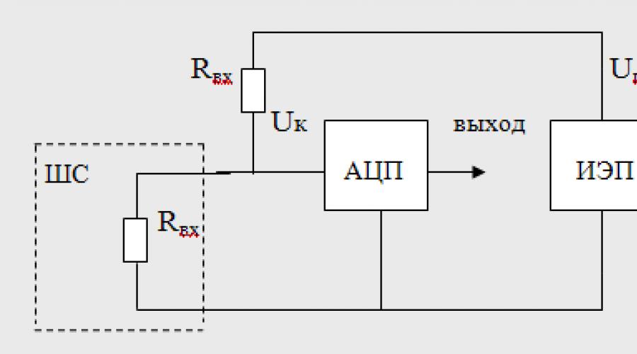
The control method with a direct current power supply involves continuous monitoring of the input resistance of the alarm loop. Figure 2.5 shows a diagram of a typical control unit of a control panel. In the AL control unit, the input resistance is determined by the amplitude value analog signal Uk, removed from the divider arm, which is formed by an AL with an input resistance Rin and a measuring element - a resistor - R and:
U = U p R in / (R in + R and)

Rice. 2.5. Diagram of a typical control unit of a control panel.
The output of the analog-to-digital converter (ADC) is set to
Two voltage thresholds corresponding to the upper and lower limits of the zone of permitted values of the AL input voltage. During operation and changes in AL resistance and “leakage” resistance input impedance The AL should not go beyond the permissible values. Because exact value threshold can only be set with a certain error determined by the technological spread R and the error of the ADC, then in this case under valid value This implies upper and lower threshold zones. When R reaches the upper (which corresponds to a break in the alarm loop) or lower threshold (which corresponds to a short circuit of the alarm loop conductors), the device must switch to alarm mode. The optimally selected value is considered to be the value of the remote resistor (load resistance), which ensures control of the alarm loop with the specified parameters and generation of an “Alarm” notification when the detector installed in this alarm loop is triggered.
A.V. Rodionov
Deputy Head of the Systems Engineering Department of NVP "Bolid"
Many articles have been written about the fact that radial systems are increasingly being replaced by modern addressable analog systems, which have potentially greater reliability, functionality and information content. Of course, this is true, but radial systems do not stand still!
What are radial alarm systems? Let us define right away that within the framework of this article, by “radial” we mean traditional wired alarm systems, the basis of which is the alarm loop.
Radial signaling systems also have another name - beam. This is due to the fact that each loop forms a kind of beam or radius emanating from the center, which is the control panel.
Advantages of radial signaling systems
Using modern algorithms digital processing signals in receiving and control devices can significantly increase the reliability of signal detection from detectors and, as a result, reduce the likelihood of false alarms. If we talk about the reliability of the detectors themselves, the indicators are almost the same for both modern threshold and addressable detectors, the elemental base of which and the methods for detecting alarm/fire factors largely coincide. Radial signaling systems have the right to further successful existence according to the following (far from complete) number of indicators:
- versatility: any detectors work with any control panels;
- the possibility of implementing security and fire zones on one control panel;
- low criticality to parameters wire line train;
- acceptable reliability indicators;
- widespread;
- applicability for most types of objects;
- wide range domestic producers;
- low cost.

It is worth noting that radial systems are not always the best way suitable for certain types of objects. For large facilities where several thousand fire detectors need to be installed and maintained, they are more suitable analogue addressable systems, since the total costs per detector will be less than in radial systems, and the number of detectors will be less. However, for small and medium-sized objects the cost technical means protection, as well as the costs of their installation and maintenance will be lower. In addition, for security alarm purposes, contact detectors are traditionally used, which are ideally suited for radial control panels.
But the main indicator, of course, remains the market demand for wired radial fire alarm systems: according to expert assessments, the share of such systems accounts for up to 70% of the domestic market.
A little history
One of the first alarm systems to appear in our country was created on the basis of a post telephone communication in the State Hermitage. It was a burglar alarm that used previously installed telephone lines. Until the 1990s. Most of the control panels were used as equipment that combined the functions of security and fire alarms, while the tactics for working with both security and fire detectors were the same. The introduction of new standards required the manufacturers of PPCP to separate these functions. The accumulated experience in the development and operation of domestic devices proved the possibility of combining security and fire functions on one device, and computing tools that were sufficiently developed at that time made it possible to implement this unique opportunity without contradictions in terms of the requirements of the standards for security and fire alarms. In the fact that this phenomenon, unique in world practice, has become a reality, a huge role belongs to the Okhrana Research Center, which at that time was part of the VNIIPO. At the same time, foreign addressable, addressable-analog and radio channel fire alarm systems began to appear on the market, however economic crisis 1998 acutely highlighted the need to develop their domestic functional analogues. Over the past years, developers have worked intensively to solve this problem, and now whole line domestic manufacturers produce their own systems, which are not inferior in quality or functions to foreign ones.
Radial systems also developed: fire control panels learned to determine the number of triggered detectors in a loop (single-threshold and double-threshold fire loops), a verification procedure was introduced for the one triggered from the broadcaster; For security control panels, such functions as protection against sabotage (substitution of a detector), control of opening the detector body, control of a disarmed alarm system, automatic arming of the alarm system, etc. have become available.

Features of use
Let's consider some features of using wired radial fire alarm systems.
Security loops
The tactics of operation of security loops are quite simple: the loop can be either normal (protected), or in alarm, or disarmed. Any violation (transition beyond the normal range) of the armed loop automatically puts it into alarm mode. Majority security detectors work to break the loop during an alarm, but what if an attacker decides to block the transmission of an alarm message by jumping the external wires of the loop connected to the detector? To protect against this type of sabotage, modern receiving and control devices monitor a sharp change in the resistance of the loop, even by a small value. If you install a hidden resistor of a small value inside the detector body, the device will detect an abrupt change in resistance in the loop at the moment the jumper is connected and go into alarm mode. At the same time, if the resistance of the loop changes smoothly, for example, in the case of a change in leakage between the AL wires or the wire and the ground, the device should not interpret these changes as an attempt at sabotage. In Fig. Figure 1 conventionally shows circuits and diagrams of loop resistance in both cases.
However, what if the attacker turned out to be more cunning and installed a jumper inside the detector body, at the alarm contact terminals? And in this case, you can find a way out! If the detector has a case opening sensor (tamper), the device will record the fact that the detector case has been opened, which, of course, should attract the attention of the security service. And finding and eliminating the jumper is already a trivial task for engineering service. Circuits and loop resistance diagrams for this case are shown in Fig. 2.
Of course, the task of protecting against possible sabotage is not solved only by these methods, but when reasonable approach The considered features of the implementation of a security alarm will prevent material losses and significantly save time and effort when searching for potential points of attack by an attacker.

Fire plumes
The operating tactics of fire lines are significantly different from those of security lines. For fire alarms, the main thing is a reasonable compromise between two tasks:
- do not issue a false fire report;
- respond to the presence of fire factors. The function of determining fire factors and transmitting an alarm message is performed by fire detectors, and the control panel must be able to reliably detect this notification and decide how to respond to it in order to avoid possible losses both from the fire itself and from the consequences of the operation of the means. fire automatics.
What features of the implementation of fire trails can be useful in this case?
- The ability to automatically reset the fire detector to return it to its original state after activation. This feature is extremely important for implementing the verification function (request) of a detector triggered in a loop. Detectors are not perfect and may generate false fire alarms. To make sure that the notification is not false, the device resets the detector and waits for it to trigger again. Only after repeated activation is a decision made about the presence of a fire hazard in the protected area.
- Possibility of detecting several triggered detectors in one loop. As is known, the equipment of the fire alarm system, when at least two fire detectors are triggered, must generate control commands automatic installations fire extinguishing, or smoke removal, or fire warning, or control of engineering equipment of objects. For loops that can distinguish between the activation of one, two or more detectors, a special designation has been introduced: two-threshold. The use of two-threshold loops allows you to save on the number of detectors installed in one room (three detectors in one loop, instead of four in two loops for single-threshold AL), and also save on wires. In Fig. Figure 3 shows diagrams and diagrams of two-threshold fire alarm systems.
- Implementation of mechanisms that minimize the influence of transient processes in loops. Internal circuits Most detectors can be represented in the form of an equivalent RC circuit, which allows one to evaluate the processes occurring in a loaded loop. The more detectors included in a loop, the higher its equivalent capacity. The higher the loop capacity, the longer the time it takes to complete transient processes.
In what cases do transient processes occur in loops and what can they affect? It is necessary to take into account transient processes primarily in loops with alternating voltage. Each time the polarity is changed, charge/discharge cycles of the internal capacitance of the detector occur, and the voltage in the loop does not “equalize” immediately. As a rule, control and control devices maintain a certain pause before starting to measure the voltage in the loop after changing the polarity. The duration of such a pause must obviously be greater than the duration of the transition process and, as a rule, is hundreds of milliseconds (200-300 ms). But this time may not be enough if there are too many detectors in the loop! In this case, the duration of the transition process is longer than the pause allotted for its completion, and the measurement results are distorted. This effect is also inherent in loops with constant voltage: in the event of a power supply voltage drop in the loop or in the event of a break in the terminal element of the loaded loop. Distortion of the results of measuring the parameters of the loop under the influence transition period may cause a false fire signal to be generated. This must be taken into account when calculating the number of detectors included in one loop. Voltage diagrams in alarm loops during transient processes are shown in Fig. 4. How to minimize the influence of transient processes if the calculation maximum quantity detectors in a loop is determined only by the maximum load current of the loop, and the nonlinear characteristics of the detectors are not given? This problem must be solved by the receiving and control device itself, actually calculating the derivative of the process of changing the state of the loop. This may somewhat delay the response time when the detector is triggered, but it reliably protects against false alarms.

Development prospects
As already noted, it is premature to write off traditional radial signaling systems. Among the promising tasks is further expansion of the functionality of such systems in terms of integration with engineering systems objects. Development of the so-called technological alarm system based on hardware existing systems security-
fire alarm is justified by the fact that most engineering equipment(pumps, valves, gate valves, etc.) has contact outputs that are ideal for inclusion in radial trains alarms. In addition, work is constantly underway to improve the reliability of wired radial systems. Here we can distinguish three components, each of which contributes to the overall reliability indicator:
- detector;
- wired loop as a communication channel;
- receiving and control device.
Evolution of radial system segments
Looking back about 10 years ago, we will see the development path that detectors have gone through and what a huge amount of work has been done. If the external design of the detectors has changed slightly, then internal filling has evolved quite significantly. The use of microcontrollers has made it possible to use mathematical methods processing signals from primary converters responding to fire or alarm factors. This allows you to filter out random or induced noise, adjust the threshold level of the alarm factor if necessary, and accumulate data on its changes over time. Developed self-diagnosis functions of smoke fire detectors now make it possible to detect a malfunction of the optical channel or a malfunction of the detector’s own circuit, preventing the formation of false fire signals. Further improvement in the reliability of detectors, multifactor detection of alarm/fire, and the use of new methods and algorithms of operation determine the ways of their development. Following the development of detectors, control and monitoring devices have also gone through a similar path of development. But the most “underdeveloped” segment of radial systems remains the loop itself, as a communication channel between detectors and a control panel. Nowadays, having a two-wire line for transmitting a binary state is an unaffordable luxury. In the long term, when the cost of an addressable analogue detector approaches the cost of a traditional threshold detector, radial systems will give way to their leading positions, but in near future, while the cost of addressable systems is quite high, there is no broad alternative to radial systems. But this statement does not mean that radial systems will not develop.
Hybrid systems
There are already hybrid systems on the market that combine the advantages of targeted and threshold systems. In such hybrid systems, called polling address-threshold systems, the following advantages of address systems are realized:
- positioning of the fire/intrusion location accurate to the location of the detector;
- performance check and automatic identification of each faulty detector;
- indication of need Maintenance detector;
- possibility of loop branching;
- no need to break the cable when removing the detector from the socket.
The prospect for the development of radial systems, in the author’s opinion, lies in the combination of conventional threshold loops and interrogating address-threshold alarm loops within one device. For the price of one addressable threshold detector, will probably be comparable to the cost of two traditional threshold detectors, but for small and medium-sized objects their use will reduce the cost of the system as a whole. If there is a serviceability monitoring function, it is allowed to install one detector in a room instead of two conventional threshold ones.
So, at the end of the article we can draw the following conclusions:
- for small and medium-sized objects, radial OPS systems are the most effective in terms of costs, reliability and functionality rational decision;
- use of sabotage protection mechanisms security zones potentially reduces the risk of material losses;
- verification of the state of fire detectors, as well as taking into account the influence of transient processes in fire loops can minimize the number of false fire signals;
- the use of two-threshold fire plumes allows optimizing costs for materials and equipment;
- A promising direction for the development of radial OPS systems: interrogation address-threshold systems.
An alarm loop (AL) is an electrical circuit containing:
- sensors (DS);
- connecting wires;
- terminal (OU), switching, as well as loop control devices (LCD).
This is the definition for a wired loop, and Figure 1 shows block diagrams the most common options.
I would like to draw your attention to the ambiguity in the interpretation of the state of dry contacts (relays) in the “classical” technical understanding and use for security alarm systems. It would be correct to call the contacts normally closed (NC) for a device that has them closed when not in use. For normally open (NO), naturally the opposite is true.
For some reason, alarm sensors (detectors) are considered to be in a closed state when the detector is turned on. Indeed, when the detector is turned on and goes into the “normal” state, the contacts close, but this is a working state, which means they must be considered NR. In order to avoid confusion, it is better to look at how the alarm signal is generated:
- opening;
- or by closing relay contacts.
The vast majority of sensors use the first option (Fig. 1a). I dwell on this in such detail so that you understand the principle of operation of the alarm loop and the security system as a whole. In the security mode, which is characterized by the supply of supply voltage to the detectors and the absence of influences causing the sensor to enter an alarm state, the AL is a closed circuit.
For the control panel (RCD), this is evidence that everything is normal at the controlled object. The control panel monitors the current flowing through the loop and if its value deviates upward or downward, it generates an alarm signal.
In order to provide the required current value, a terminal device is included in the loop - usually a resistor. Terminal devices may consist of other elements or combinations thereof, but this is not typical for most security systems.
By the way, the passport for the control device must indicate which element is used as the terminal element.
In order for current to appear in the loop, voltage must be applied to it. The PKP does this. Its terminal block indicates the polarity of the connection, which sometimes needs to be taken into account - more on that later.
Let's see in what cases the security alarm loop can open.
- as a result of an impact on the sensor, causing it to go into an alarm state;
- loss of supply voltage to active detectors;
- break or short circuit of the electrical circuit.
The first mode indicates intrusion detection (except for cases of false alarms). The other two are the result of various components of the alarm system malfunctioning. By the way, if sensors are used that generate an alarm signal by closing the contacts (Fig. 2b), then in the “alarm” mode the loop will be closed.
TYPES AND TYPES OF SIGNALING LINES
Loops can be classified according to several criteria, for example:
- method of connection to the device;
- types of detectors used.
In the first case, two types can be distinguished: radial (Fig. 2a) and annular (Fig. 2b). The latter is quite rare and is used mainly in addressable fire alarm systems.

If we talk about the types of sensors used, then we can talk about threshold loops (Fig. 1a-b), which sharply change their electrical parameters when switching to the “alarm” mode, and address ones (Fig. 2c).
I have already talked about the first ones, but let’s look at addressable alarm loops now.
They are called so due to the addressable alarm sensors they use. In this case, one at a time two-wire line information about the state of the sensor is transmitted (in digital form) and supply voltage is supplied. Due to the unique address, each detector can be uniquely identified by the system.
In this case, when connecting the loop, observing the polarity indicated on the terminals of the control panel and security sensors is mandatory. In addition, the number of detectors connected to the addressable AL is limited and is determined technical characteristics device.
INSTALLATION OF SECURITY Loops
Let's start with the fact that the alarm loop is a low-current circuit and its installation must be carried out taking into account the relevant standards and regulations. The main one is to ensure that when laying in parallel with power circuits, the distance between them is at least 50 cm. The intersection of these circuits is allowed only at right angles, etc.
Since when laying the AL it is necessary to ensure its protection from accidental damage, it is not allowed to lay wires without attaching them to load-bearing structures. The most typical example of how not to do it and how it is done anyway is the free placement (dragging) of cables in the ceiling space, for example, behind Armstrong ceilings.
Guiding Documents private security In order to avoid sagging of the connecting lines of security alarm systems, they are prescribed to fasten them in increments of, in my opinion, 50 cm to the walls and ceiling. With open installation, this becomes irrelevant, since there are electrical boxes and corrugated hoses that:
- firstly, they allow you to comply with the rules for laying cables;
- secondly, they simplify and speed up the installation process.
In addition to the requirements for the installation of alarm loops as low-current circuits, there are also rules for ensuring the reliability of their subsequent operation and ease of maintenance. There may be some contradictions here.
For example, from a maintenance point of view, access to the alarm system should be as convenient as possible, and from a security point of view, it is necessary to prevent the possibility of unauthorized access to wires and sensors.
Moreover, if during protected times it is difficult to carry out any manipulations with the loop, then during the period when the alarm system is disabled, turn off part of the loop or sensors for knowledgeable person won't be difficult. Moreover, after this the alarm will work as before, only part or all of the premises will be unprotected.
To solve this problem, the following measures can be taken:
- sealing (sealing) of instrument cases, distribution boxes, places of possible opening of electrical boxes;
- hidden installation alarm sensors;
- installation of loop monitoring devices.
The first two points are quite obvious. The AL monitoring device allows you to determine its breakage. On the one hand, it may indicate a malfunction of the loop, on the other hand, it will indicate that part of the loop is disconnected. The connection of the CCTV is made at the point farthest from the control panel and its visual control must be carried out every time the object is put under protection.
However, what has been said applies to security systems, installed in places with stay large quantity unauthorized persons: shops, offices, etc. The risk of such interference in an alarm system installed in a country house, in a private house or apartment is practically absent.
* * *
© 2014-2020 All rights reserved.
The materials on the site are for informational purposes only and cannot be used as guidelines or normative documents.