Closed switchgears and substations. Equipment for open switchgears and substations Switchgears and substations
Read also
Each substation has distribution devices (RU) containing switching devices, protection and automation devices, measuring instruments, prefabricated and connecting busbars, auxiliary devices.
Based on their design, reactor plants are divided into open and closed. They can be complete (assembled at the manufacturer) or prefabricated (assembled partially or completely at the site of use).
Open switchgear (OSD) - a switchgear, all or the main equipment of which is located on outdoors; closed switchgear (SGD) - a device whose equipment is located in a building.
Complete switchgear (KRU) - a switchgear consisting of cabinets, fully or partially closed, or blocks with built-in devices, protection and automation devices, measuring instruments and auxiliary devices, supplied assembled or fully prepared for assembly and intended for indoor installation.
Complete switchgear outdoor installation(KRUN) is a switchgear designed for outdoor installation.
Complete transformer (converter) substation (KTP) - a substation consisting of transformers (converters) and switchgear or switchgear units, supplied assembled or fully prepared for assembly.
Distribution switching point (RP) is a distribution device designed for receiving and distributing electricity at one voltage without conversion and transformation.
Chamber - a room intended for installation of devices and tires: a closed chamber is closed on all sides and has solid (not mesh) doors; the fenced chamber has openings protected in whole or in part by non-continuous (mesh or mixed) fences.
Each substation has three main units: high voltage switchgear, transformer, low voltage switchgear.
Purpose and classification of substations. A substation is an electrical installation consisting of transformers or other energy converters, switchgear with voltages up to 1000 V and higher, used for the conversion and distribution of electricity.
Depending on the purpose, substations are made as transformer (TP) or converter (PC) - rectifier ones.
Transformer substations are the main link of the power supply system. Depending on their position in the power system, purpose, and the value of the primary and secondary voltages, they can be divided into district substations, substations industrial enterprises, traction substations, substations of the city electrical network, etc.
District and hub substations are powered by district (main) power system networks and are designed to supply power to large areas where industrial, urban, agricultural and other electricity consumers are located. Primary voltages of district substations are 750, 500, 330, 220, 150 and 110 kV, and secondary voltages are 220, 150, 110, 35, 20, 10 or 6 kV.
Transformer substations are located on the territory of industrial enterprises the following types:
Factory substations, which are carried out as: a) main step-down substations and deep input substations with an open switchgear for receiving electricity from energy systems with a voltage of 110-35 kV and converting it into a factory network voltage of 6-10 kV for powering shop and inter-shop substations and powerful consumers ; b) substations and distribution points with closed switchgear, with the installation of high-voltage equipment of 6-10 kV type KSO or KRU and transformers of 6-10/0.4 kV.
Shop substations designed to power one or more shops are made:
a) free-standing, attached and built-in with the installation of transformers in closed cells And distribution boards for voltage 0.4-0.23 kV;
b) in-shop mainly as complete package type transformer substations with the installation of one or two transformers with a power of 400 kVA and higher, located in separate room workshop or directly in the workshop, depending on environmental conditions and the nature of production.
Switchgears power stations and substations are carried out closed (indoor installation) - with the equipment located in buildings (ZRU) and open (external installation) - with the location of all or the main equipment in the open air (ORU). Wide Application find complete switchgears for both indoor installation (KRU) and for outdoor installation (KRUN). When designing and constructing switchgears, complete 6-10 kV cells, complete switchgears, as well as individual factory-made units are currently used.
Switchgears 35-750 kV are usually made open.
Closed switchgears are mainly used at voltages of 3-20 kV, as well as at voltages of 35-220 kV in cases of limited space for switchgear, increased atmospheric pollution and severe climatic conditions (Far North). Recently, complete gas-insulated switchgears (SF6) insulation (GIS) have begun to be introduced into power systems. They can be made for both indoor and outdoor installation. Currently, GIS 110-220 kV are in operation and GIS 330-1150 kV are being developed. The use of switchgear instead of standard outdoor switchgear makes it possible to reduce the area and volume of the switchgear by approximately 6-10 times, increase the reliability of operation and the operating standards of electrical installations, but requires approximately twice the capital investment.
Lecture No. 6 “Switchgears and substations”
Requirements for buildings and structures of distribution devices.
In switchgear rooms, doors and windows must always be closed, and openings in partitions between devices containing oil must be sealed. All holes where the cable passes are sealed. To prevent the entry of animals and birds, all holes and openings in the external walls of the premises are sealed or covered with mesh with a mesh size of (1´1) cm. Live parts of ballasts and protection devices must be protected from accidental touches. In special rooms (electrical machine rooms, switchboards, control stations, etc.) it is allowed open installation devices without protective covers. All switchgear (boards, assemblies, etc.) installed outside the outdoor switchgear fences and enclosed spaces must have locking devices that prevent non-electrical personnel from accessing them. Electrical equipment of switchgear systems of all types and voltages must satisfy operating conditions, both under normal conditions and during short circuits, overvoltages and overloads. The insulation class of electrical equipment must comply rated voltage network, and surge protection devices - to the insulation level of electrical equipment. When electrical equipment is located in an area with a polluted atmosphere, measures must be taken to ensure reliable insulation operation:
Heating by induced current of structures located near live parts through which current flows and accessible to personnel should not exceed 50°C. Air temperature inside the indoor switchgear in summer time should be no more than 40°C. If it increases, measures must be taken to reduce the temperature of the equipment or cool the air. Room temperature compressor station must be maintained within (10 ¸ 35) ° C; in the premises of gas-insulated switchgears (hereinafter referred to as GIS) - within (1 ¸ 40)°C. For temperature detachable connections Inspection of tires in the switchgear must be organized according to the approved schedule. Distances from live parts of the outdoor switchgear to trees, tall bush must be such that the possibility of overlap is excluded. The covering of floors in closed switchgear switchgears, switchgear switchgears and switchgear switchgear must be such that there is no formation of cement dust. Premises intended for the installation of cells of a complete gas-insulated switchgear (hereinafter referred to as GIS), as well as for their inspection before installation and repair, must be isolated from the street and other premises. Walls, floors and ceilings must be painted with dust-proof paint. Rooms must be cleaned using a wet or vacuum method. The premises must be equipped supply and exhaust ventilation with air suction from below. Air supply ventilation must pass through filters that prevent dust from entering the room.
In this lecture we will look at Consumer substations with voltages from 0.4 to 220 kV. The Consumer switchgear room adjacent to premises owned by third parties and containing live equipment must be isolated from them. It must have a separate, lockable exit. The switchgear equipment, which is in the service of Consumers and used by the energy supplying organization, must be controlled on the basis of instructions agreed upon by the Consumer and the energy supplying organization. In switchgear rooms, doors and windows must always be closed, and openings in partitions between devices containing oil must be sealed. All holes where the cable passes are sealed. To prevent the entry of animals and birds, all holes and openings in the external walls of the premises are sealed or covered with mesh with a mesh size of (1´1) cm. Live parts of ballasts and protection devices must be protected from accidental touches. In special rooms (electrical machine rooms, switchboards, control stations, etc.), open installation of devices without protective covers is allowed. All switchgear (boards, assemblies, etc.) installed outside the outdoor switchgear fences and enclosed spaces must have locking devices that prevent non-electrical personnel from accessing them. Electrical equipment of switchgear systems of all types and voltages must satisfy operating conditions, both under normal conditions and during short circuits, overvoltages and overloads. The insulation class of electrical equipment must correspond to the rated voltage of the network, and surge protection devices must correspond to the insulation level of electrical equipment. When electrical equipment is located in an area with a polluted atmosphere, measures must be taken to ensure reliable insulation operation:
In open switchgears (hereinafter referred to as open switchgears) - strengthening, washing, cleaning, coating with hydrophobic pastes;
In closed switchgears (hereinafter referred to as closed switchgears) - protection from the penetration of dust and harmful gases;
In complete outdoor switchgear, cabinets are sealed and insulation is treated with hydrophobic pastes.
Heating by induced current of structures located near live parts through which current flows and accessible to personnel should not exceed 50°C. The air temperature inside the indoor switchgear in the summer should be no more than 40°C. If it increases, measures must be taken to reduce the temperature of the equipment or cool the air. The air temperature in the compressor station room must be maintained within the range (10 ¸ 35) ° C; in the room of gas-insulated switchgear (hereinafter referred to as GIS) - within (1 ¸ 40)°C. The temperature of detachable busbar connections in the switchgear must be monitored according to an approved schedule. The distances from live parts of the outdoor switchgear to trees and tall bushes must be such that the possibility of overlap is excluded. The covering of floors in closed switchgear switchgears, switchgear switchgears and switchgear switchgear must be such that there is no formation of cement dust. Premises intended for the installation of cells of a complete gas-insulated switchgear (hereinafter referred to as GIS), as well as for their inspection before installation and repair, must be isolated from the street and other premises. Walls, floors and ceilings must be painted with dust-proof paint.
Cleaning of premises should be done using wet or vacuum methods. The premises must be equipped with supply and exhaust ventilation with air suction from below. The supply ventilation air must pass through filters that prevent dust from entering the room.
The outdoor switchgear (TP) provides passage along switches for mobile installation and repair mechanisms and devices, as well as mobile laboratories; the passage clearance must be at least 4 m in width and height (Fig. 1).
Flexible busbars are mounted from stranded wires. Connections of flexible busbars are made in the loops at the supports by welding, and branches in the span are made in a way that does not require cutting the busbars.
The outdoor switchgear buses are suspended on single garlands of insulators. Double garlands are used only in cases where a single garland does not meet the conditions of mechanical strength. The use of dividing (mortise) garlands is not allowed; fastening of flexible tires and cables in tension and suspension clamps in terms of strength must comply with the requirements given in the PUE. When determining loads on flexible busbars, the weight of garlands of insulators and descents to devices and transformers is taken into account, and when calculating loads on structures, additionally the weight of a person with tools and installation devices.
The mechanical safety factor for suspended insulators under loads must be at least 3 in relation to the test load. Calculated mechanical forces transmitted at short circuit rigid busbars on support insulators, are accepted in accordance with the requirements of the PUE.
The mechanical safety factor in coupling fittings for flexible tires under loads must be at least 3 in relation to the breaking load.
For fastening and insulating wires and lightning protection cables in open switchgears (OSD), suspended insulators are used, which consist of an insulating body (glass PS or porcelain PF), a cap made of malleable cast iron, and a steel rod. With the help of a cement bond, the cap and the rod are reinforced in an insulating body. PS and PF insulators are designed to work in areas with an unpolluted atmosphere, and PSG and PFG - in areas with a polluted atmosphere.
Rice. 1. Plan and sections of a typical 110/6-10 kV gas substation with two transformers with a capacity of 40 MB A:
a - plan; b- section; 7 - outdoor switchgear 110 kV; 2 - closed switchgear 6-10 kV; 3 - transformer; 4- VL 110 kV; 5 - repair area; 6 - lightning rod; 7- security cable; 8- disconnector; 9- separator; 10 - short circuit; 11 - spark gap; 12 - railway track; 13 - leads from split windings of the transformer 
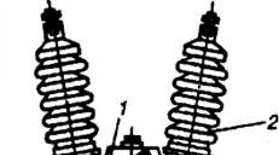
Rice. 2. Switch MKP-35 in a section along the pole:
1- drive mechanism; 2, 5 - inputs; 3 - cover; 4 - current transformer; 6 - pipe; 7- rod; 8 - arc extinguishing device; 9-moving contacts
Power oil switches are designed to turn on, turn off and switch operating currents during normal operation and short-circuit currents during emergency modes that may occur in outdoor switchgear lines. Depending on the arc extinguishing medium, circuit breakers are divided into liquid and gas. The most common liquid switches are oil switches, which, depending on their volume, are classified into high-volume and low-volume. For outdoor switchgear substations with a voltage of 35 kV, multi-volume oil circuit breakers of the S, MKP, U, etc. series are widely used.
MCP switches are classified as oil-based, high-speed three-phase devices with a separate tank for each phase. All poles of the switches are interconnected and controlled by the drive. The switches have two breaks per pole and are used for currents of 0.63 and 1 kA for voltages of 35-110 kV and outdoor installation. In 35 kV circuit breakers, three tanks (phases) are mounted on common frame, and at 110 kV each tank is installed separately on the foundation. All switches have built-in current transformers.
The design of the MKP-35 switch for a voltage of 35 kV is shown in Fig. 2. Two inputs 5 are mounted on the cover 3, outer part which are protected by porcelain insulators 2 Under the cover
current transformers 4 and a drive mechanism / assembled in a welded housing are installed. At the bottom of the body there is a bakelite guide pipe 6 with an internal oil buffer. An insulating rod 7 passes through the buffer and the guide pipe, at the bottom of which movable contacts 9 are reinforced. At the lower end of the conductive rod, a fixed contact and an arc extinguishing device 8, made on the principle of a cross-slit oil blast chamber, are mounted.
Air circuit breakers VVU-35A are also switching devices installed on outdoor switchgear high voltage for breaking electrical circuits under load and disconnecting short-circuit currents.
The arcing chamber of such a circuit breaker has two main breaks. Each gap is bridged by its own active resistance with auxiliary contacts. Uniform distribution of voltage between the two breaks is ensured by shunt capacitors placed in a porcelain cover. The leads into the arc chute are made of epoxy compound and protected from moisture by porcelain covers. Arcing chambers of 35 kV circuit breakers are installed on a support column made of hollow porcelain insulators.
Two fiberglass air ducts pass inside the supporting insulation of the chamber: one for supply compressed air into the arc-extinguishing chambers, the other for pulsed air supply when turned off and reset when turned on.
The base of the pole or its element is a frame with a plinth, which is connected copper pipes With distribution cabinet switch. The cabinet is connected to the air duct of the substation compressor unit.
For manual switching on and off of de-energized sections of electrical circuits that are under voltage, as well as grounding of disconnected sections, if they are equipped with stationary grounding devices, disconnectors are used.
Disconnectors of the RND series (3) of the horizontal rotary type are manufactured in the form of individual poles. Steel frame, at the ends of which two bearing units, serves as the basis of each pole.
The bearings rotate shafts with supporting insulating columns, on the upper flanges of which contact system knives and contact leads are fixed. The latter are connected to the main knives by flexible conductors made of strip copper. The detachable contact of the main knives of the contact system consists of lamellas connected in pairs by a tie rod or bolt with a spring that provides the necessary contact pressure.
The pole of the disconnector to which the drive is connected is called leading, the remaining poles connected by rods to the driving pole are called driven. When operating the disconnector, the contact knives are rotated at an angle of 90°.
The grounding knife is a steel tube, one end of which is equipped with a lamellar contact, the other is welded to its shaft. The fixed contact of the grounding knife is mounted on the contact knife of the disconnector. The grounding knives are turned on and off manually, and the main contact knives are turned on and off manually, by an electric motor or pneumatic drive.
Separators are used to automatically disconnect a de-energized damaged section of a line or transformer. Single-pole separators for a voltage of 35 kV are connected into one three-pole device. The separator drive provides automatic shutdown and manually turning on the device.
Short circuiters KRN-35 are designed to create an artificial short circuit, causing disconnection of the protective supply line of the circuit breaker.
The short circuiter consists of a base, an insulating column on which a fixed contact is fixed, and a grounding knife, connected to the drive by a rod. The base of the short circuit is welded structure, designed for installing an insulating column with a fixed contact. For collaboration short-circuiter with a separator, a TSHL-0.5 current transformer is built into the grounding circuit, the secondary windings of which are connected to the separator drive relay. The base of the short circuit is isolated from the ground by insulators. The drive rod has an insulating insert. After switching on the short circuiter, the current passes through the circuit: supply bus - fixed contact - grounding blade - flexible connection- a busbar located on the insulating strip of the base, - a grounding busbar passed through the window of the current transformer, - earth.
TFEM-35 current transformers are manufactured as single-stage ones. They consist of a primary and secondary winding placed in a porcelain cover filled with transformer oil. The windings are made in the form of two links inserted into one another. The primary winding is made of two or four sections, which are connected in series, parallel and mixed depending on the transformation ratio. Switching of sections is carried out by jumpers on the terminals of the primary winding.
Voltage transformers are conventional step-down transformers low power. They are manufactured single- and three-phase. The secondary (lower) voltage, at which measuring instruments and protection devices are turned on, of all voltage transformers is 100 V. Such transformers are used to power the voltage coils of measuring instruments.
Power transformers are designed to increase or decrease voltage alternating current(Fig. 3).
Currently, various power transformers are used, which are characterized by rated power, voltage class, operating conditions and modes, and design. Depending on the rated power and voltage class, they are divided into several groups (dimensions).
According to operating conditions, the nature of the load or operating mode, power transformers are distinguished general purpose, adjusting and special (mine, traction, converter, starting, electric furnace). 
Rice. 3. Three-phase three-winding transformer with a power of 16 MB * A 110/38, 5/11 kV:
1 - high voltage inputs (h.n.); 2 - medium voltage inputs (s.n.); 3- insulating cylinder; 4 - low voltage inputs (LV); 5 - switch drive; 6- exhaust pipe; 7- expander; 8- magnetic circuit; 9 - winding tap switch (v.n.); 10- winding (v.n.); 11 - shielding turns of the winding (v.n.); 12 - thermosyphon filter; 13 - trolley; 14 - transformer tank; 15- tubular radiator; 16 - electric fans
The symbol for various transformers consists of letters characterizing the number of phases and windings, the type of cooling and tap switching, and numbers characterizing the rated power and voltage class, the year of manufacture of the transformer of this design (the last two digits), Climatic performance and accommodation category.
The letter T denotes three-winding transformers (they do not have two-winding designations), the letter H denotes transformers with an on-load tap-changer. Other letters are also used: A (for autotransformers before designating the number of phases), P (for transformers with a split LV winding after designating the number of phases), 3 (for sealed oil transformers or with a non-flammable liquid dielectric with a protective nitrogen cushion after designating the type of cooling), C (for transformers own needs at the end letter designation).
The rated power and voltage class are indicated through a dash after the letter designation in the form of a fraction (numerator - rated power in kilovolt-amperes, denominator - voltage class of the transformer in kilovolts).
Designs of transformers intended for operation in certain climatic regions are designated by the letters U, XL, T (with moderate, cold, tropical climates).
Currently, the electrical industry produces oil transformers of sizes I and II (power up to 630 kV * A, voltage class up to 35 kV) types TMG and TMVG new series. Distinctive feature These transformers have a detachable sealed design of the tank, which eliminates contact of the internal volume of the transformer with the environment.
These transformers are completely filled with transformer oil, up to the cover, and temperature fluctuations in its volume are compensated by changing the volume of the tank with corrugated walls. Transformers are filled with degassed oil under deep vacuum.
Depending on the type of transformer, the tank is made oval or rectangular shape. It consists of an upper corner frame, a corrugated wall made of thin sheet steel, a lower shell with a welded bottom. The oil conservator, thermosiphon and air filters and cooling radiators. The hermetically sealed design and the use of corrugated tank walls make it possible to significantly reduce weight and dimensions. The service life of transformers is 25 years with a reduced amount of maintenance and without major repairs. However, transformers of the TMG and TMVG types require more high level installation and operation. The corrugated walls of the tank are made of thin sheet steel and are sensitive to mechanical stress. Therefore, installation and operating personnel must exercise extreme caution during transportation, installation and current repairs sealed transformers. When transporting transformers, securing them using plates is not allowed.
Currently, a new series of 35 kV transformers with a capacity of 1000-6300 kV * A is being introduced. The weight of the new series of transformers and no-load losses have been reduced by an average of 20%.
Distribution device (RU) They call an electrical installation that serves to receive and distribute electricity and contains switching devices, busbars and connecting buses, auxiliary devices (compressor, battery, etc.), as well as protection devices, automation and measuring instruments.
Switchgear of electrical installations are designed to receive and distribute electricity of one voltage for further transmission to consumers, as well as to power equipment within the electrical installation.
If all or the main equipment of a switchgear is located in the open air, it is called open (OSU): if it is located in a building, it is called closed (ZRU). Switchgear consisting entirely or partially closed cabinets and units with built-in devices, protection and automation devices, supplied assembled or fully prepared for assembly are called complete and are designated for internal installation of switchgear, for external installation - KRUN.
Power center - a generator voltage distribution device or a secondary voltage distribution device of a step-down substation, to which the distribution networks of a given area are connected.
Switchgears (SD) are classified according to several criteria; below we present their types and design features.
Switchgears up to 1000 V
Switchgears up to 1000 V are made, as a rule, indoors in special cabinets (panelboards). Depending on the purpose, 220/380 V switchgears (voltage class 0.4 kV) can be designed to power consumers or exclusively for the electrical installation’s own needs.
Structurally switchgears 0.4 kV have protective devices ( circuit breakers, fuses), switches, switch-disconnectors and busbars connecting them, as well as terminal blocks to connect cable lines consumers.
In addition to power circuits, a number of additional devices and auxiliary circuits, namely:
electricity meters and current transformers;
circuits for indicating and signaling the position of switching devices;
measuring instruments for monitoring voltage and current at various points of the switchgear;
signaling and ground fault protection devices (for IT configuration networks);
automatic reserve input devices;
remote control circuits for switching devices with motor drives.
Low-voltage switchgears can also include switchboards direct current, distributing direct current from converters, batteries for powering operational circuits electrical equipment and relay protection and automation devices.
High voltage switchgears
Switchgears of voltage class above 1000 V can be designed both outdoors - open type (OSU), and indoors – closed type(ZRU).
Equipment is placed in closed switchgears in prefabricated chambers for one-way service of KSO either in complete switchgears type KRU.
Cameras of the KSO type are more preferable for rooms of limited area, since they can be installed close to the wall or to each other back walls. KSO cameras have several compartments closed with mesh fences or solid doors.
CSOs are equipped with various equipment, depending on their purpose. To power the outgoing lines, a high-voltage switch, two disconnectors (on the busbar side and on the line side), current transformers are installed in the chamber; on the front side there are disconnector control levers, a switch drive, as well as low-voltage circuits and protection devices implemented to protect and control this line.
Cameras of this type can be equipped with voltage transformers, arresters (overvoltage limiters), fuses.
Switchgear type KRU They are a cabinet divided into several compartments: current transformers and outgoing cables, busbars, a withdrawable part and a secondary circuits compartment.
Each compartment is isolated from each other to ensure safety during maintenance and operation of switchgear cabinet equipment. The withdrawable part of the cabinet, depending on the purpose of the connection, can be equipped with a circuit breaker, a voltage transformer, arresters (arresters), and an auxiliary transformer.
The retractable element relative to the cabinet body can occupy a working, control (disconnected) or repair position. In the operating position the main and auxiliary circuits are closed, in the control position the main circuits are open and the auxiliary circuits are closed (in the disconnected position the latter are open), in the repair position the retractable element is located outside the cabinet body and its main and auxiliary circuits are open. The force required to move the retractable element should not exceed 490 N (50 kgf). When the retractable element is rolled out, the openings to the fixed detachable contacts of the main circuit are automatically closed with curtains.
The current-carrying parts of switchgear are made, as a rule, with busbars made of aluminum or its alloys; at high currents, the use of copper busbars is allowed, at rated currents up to 200 A - steel. Installation of auxiliary circuits is carried out insulated copper wire with a cross section of at least 1.5 square meters. mm, connection to meters - with a wire with a cross-section of 2.5 sq. mm, solder joints - at least 0.5 sq. mm. Connections subject to bending and torsion are usually made with stranded wires.
Flexible connection of the auxiliary circuits of the stationary part of the switchgear with the retractable element is carried out using plug connectors.
Switchgear cabinets, as well as grounding blades, must meet the requirements for electrodynamic and thermal resistance to through short-circuit currents. To ensure the requirements for mechanical resistance, the number of cycles that switchgear cabinets and its elements must withstand is regulated: detachable contacts of the main and auxiliary circuits, a retractable element, doors, and a grounding switch. The number of cycles of switching on and off the built-in component equipment (switches, disconnectors, etc.) is accepted in accordance with the PUE.
To ensure safety, switchgear cabinets are equipped with a number of interlocks. After rolling out the retractable element, all current-carrying parts of the main circuits that may be energized are covered with protective curtains. These curtains and barriers must not be removed or opened without the use of keys or special tools.
In stationary switchgear cabinets, it is possible to install stationary or inventory partitions to separate live parts of equipment. It is not allowed to use bolts, screws, or studs that act as fasteners for grounding. In grounding areas there must be an inscription “earth” or a grounding sign.
The type of switchgear cabinet is determined by the circuit diagram of the switchgear main circuit. Main electrical apparatus The switch that determines the design of the cabinet is the switch: low-oil, electromagnetic, vacuum and SF6 switches are used. Secondary circuit designs are extremely diverse and have not yet been completely unified.
Complete devices may have different design, for example, with gas insulation - GIS or intended for outdoor installation - KRUN, which can be installed outdoors.
Open-type switchgears provide for the installation of electrical equipment on metal structures, on concrete foundations, without additional protection from external influences. Auxiliary circuits of outdoor switchgear equipment are mounted in special cabinets that are protected from mechanical influences and moisture.
Switchgears, both closed and open types are classified according to several criteria, depending on their design (scheme).
The first criterion is the method of performing partitioning. There are switchgears with busbar sections and busbar systems. Bus sections provide power to each individual consumer from one section, and bus systems allow one consumer to be switched between several sections. Bus sections are connected by sectional switches, and bus systems are connected by bus connectors. These switches allow sections (systems) to be powered from each other in the event of a loss of power in one of the sections (systems).
The second criterion is the presence of bypass devices– one or more bypass bus systems that allow equipment elements to be removed for repair without the need to de-energize consumers.
The third criterion is the equipment power supply circuit (for open switchgear). IN in this case There are two possible scheme options - radial and ring. The first scheme is simplified and provides for power supply to consumers through one switch and disconnectors from the busbars. In a ring circuit, each consumer is powered by two or three switches. Ring circuit more reliable and practical in terms of equipment maintenance and operation.
The electrical energy generated by the stations is supplied to the point of consumption through a system of interconnected transmission, distribution and conversion electrical installations. Electricity is transmitted via overhead power lines with voltages ranging from several hundred to hundreds of thousands of volts. Electric Energy by system air networks transmitted with voltages of 35, 110, 150, 220 kV and higher on the rated voltage scale.
Installations used for receiving and distributing electricity are called switchgears (RU). They contain switching devices, busbars and connecting buses, auxiliary devices (compressor, battery and others), as well as protection, automation devices, etc. RUs include power centers (CP), distribution points (DP), distribution lines (RL).
The power center is the generator voltage switchgear of a power plant or the secondary voltage switchgear of a step-down substation of a power system with a regulation system, to which the distribution networks of a particular area are connected.

A distribution point is a substation of an industrial enterprise or city electrical network, designed to receive and distribute electricity with one voltage without converting it.
A distribution line is a line that supplies a row transformer substations from CPU or RP, as well as large electrical installations.
Switchgears can be open (open switchgear - all or main equipment is located in the open air) and closed (closed switchgear - equipment is located in the building). Particular attention should be paid to the most common complete switchgears (SGD), consisting of fully or partially closed cabinets or blocks with built-in devices, protection and automation devices, supplied assembled or fully prepared for assembly and produced for both internal and external use. outdoor installation.
A substation is an electrical installation used for the conversion and distribution of electricity and consisting of transformers or other energy converters, switchgear, control devices and auxiliary structures.
The substation at which the alternating current voltage is converted using a transformer is called a transformer station (TP). If the alternating current voltage at a transformer transformer is converted to a lower voltage, it is called a step-down voltage, and if it is converted to a higher voltage, it is called a step-up voltage.
At transformer substations, transformers are installed that serve to change the voltage. Simultaneously with the voltage transformation, the number of lines usually changes. For example, one or two high voltage lines approach a transformer substation, and several low voltage lines depart from it.
There are two types of transformer substations: open, in which the main equipment is located on open areas, and closed ones, the equipment of which is located indoors.
If voltage transformation is not performed at a substation, but only the number of lines changes, then it is called distribution.
Converter substations are used to rectify alternating current or convert direct current into alternating current. Switching devices are installed at all substations electrical networks and various control and measuring instruments.
Electrical networks are divided by voltage into low voltage networks - up to 1 kV - and high voltage networks - more than 1 kV.

Most industrial enterprises receive electricity from substations. At substations, two or more transformers are installed, through which energy from the power system is transmitted via high-voltage lines (35, 110 or 220 kV) to sectional operating (or backup) buses with a voltage of 6-10 kV.
A substation fed directly from the energy system (or a factory power plant) is called the main step-down substation (MSS) of the enterprise, and a substation at which the voltage is reduced directly to power the electrical receivers of one or more workshops is called a workshop transformer substation (TS).
Transformer and converter substations, as well as distribution devices, are supplied complete (KTP, KPP) assembled or fully prepared for assembly.
Measurement of current and voltage on distribution device buses and in electrical circuits produced using current transformers or voltage transformers, which serve to reduce the current or voltage of the primary circuits of alternating current electrical installations, as well as to power the coils of measuring instruments, relay protection and automation devices connected to their secondary windings.
Application instrument transformers allows:
![]()
- measure any voltages and currents using conventional measuring instruments with standard windings designed for a voltage of 100 V and a current of 5 A;
- separate measuring instruments and relays from voltages above 380 V, ensuring the safety of their maintenance.
The primary winding of the measuring transformer is under the influence of the measured value, and the secondary winding is closed to measuring instruments and protection devices.
Touching measuring instruments directly connected to the high voltage circuit is dangerous for humans, therefore, in this case, measuring instruments and automatic protection equipment (relays) are connected to the secondary circuit of instrument transformers, connected to the high voltage circuit only through magnetic flux in the core. In addition, instrument transformers serve to expand the measurement limits of AC devices, like additional resistors and shunts. Application of instrument transformers with different coefficients transformation allows the use of devices with standard measurement limits (100 V and 5 A) when determining a wide variety of voltages and currents.
There are two types of instrument transformers: voltage transformers and current transformers.
Voltage transformers power the voltage windings of measuring instruments and relays (voltmeters, frequency meters, meters, wattmeters, voltage relays, power relays, etc.) in installations with voltages of 380 V and higher.
Current transformers power the current windings of measuring instruments and relays (ammeters, meters, wattmeters, current, power relays, etc.).
Most industrial enterprises source their electricity from utility systems, but some enterprises obtain their energy from their own factory power plants. The generation and distribution of energy within the enterprise from its own power plants is carried out mainly in generator mode with voltages of 6 and 10 kV.
Electrical circuits of distribution devices and substations can be primary and secondary.
Primary circuits include busbar devices and current-carrying parts of devices connected in a certain sequence.

Secondary circuits include those with the help of which the primary circuits of switchgear substations carry out electrical measurements, relay protection, alarm, remote control and automation, i.e. secondary circuits provide control, protection, convenience and safe service primary circuits.
On circuit diagrams primary circuits show all the main elements of an electrical installation: busbar devices, disconnectors, switches, fuses, transformers, reactors, etc., as well as connections between them. To better imagine the operation of the installation and its individual sections, in primary schemes usually shown without electrical connections main devices and devices of secondary circuits, measuring instruments, relay protection and automation devices. Modern reactor plants may have various schemes connections.
It must be remembered that disconnecting a load-free line is associated with a break in its charging current, which is greater the longer the line.
A load switch installed instead of a disconnector allows you to turn off and turn on the line when the load is within the rated limit.
In this case, measuring current transformers are installed at the connection, and line and bus disconnectors are used to relieve voltage from the switch and current transformers during inspection, repair, testing and other work. Since operations with disconnectors are only possible when the switch is open, which breaks the current circuit, the order of disconnecting the line is as follows: first disconnect the switch, then the line disconnector and, finally, the bus disconnector. The order of switching on the line is reversed. This option for connecting to the switchgear is used for lines with heavy loads and high short-circuit current.
Typically, this scheme is used to connect air lines. In this case, the grounding knives serve to ground and short-circuit the line after disconnection, since in the disconnected line an occurrence may occur. electric charges induced by atmospheric electricity or nearby lines. The arresters are designed to discharge electrical charges of atmospheric electricity into the ground, creating significant overvoltages in the switched-on line that are dangerous for the entire installation.
In open switchgears, arresters are connected directly to the main busbars.
To disconnect this transformer from the network, use a bus disconnector (disconnection should only be done when idling transformer); protection from high and low voltage carried out by fuses.
This circuit includes a switch designed to operational switching, and relay protection (RP), the devices of which are powered by measuring current transformers.
The use of complete switchgears and transformer substations allows you to reduce the time installation work, reduce their cost and improve quality.