Do-it-yourself air plasma cutting – working technology. Assembling a homemade plasma cutter Inverter plasma cutter how to weld metal
Read also
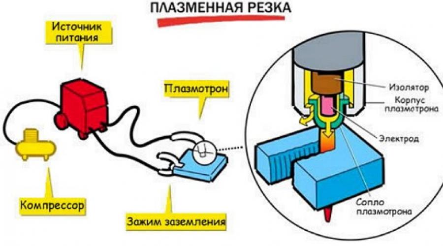
Factory plasma cutting machine. Our task: to make an analogue with your own hands
Making a functional plasma cutter with your own hands from a serial welding inverter is not as difficult as it might seem at first glance. In order to solve this problem, it is necessary to prepare all the structural elements of such a device:
- plasma cutter (also called a plasma torch);
- a welding inverter or transformer that will act as a source of electric current;
- a compressor, with the help of which a jet of air will be created, necessary for the formation and cooling of the plasma flow;
- cables and hoses for combining all structural elements of the device into one system.

Plasma cutters, including homemade ones, are successfully used to perform various jobs both in production and at home. Such a device is indispensable in situations where it is necessary to perform an accurate, thin and high-quality cut of metal workpieces. Some models of plasma cutters, due to their functionality, allow them to be used as a welding machine. This welding is performed in an argon shielding gas environment.

When choosing a power source for a homemade plasma torch, it is important to pay attention to the current strength that such a source can generate. Most often, an inverter is chosen for this, providing high stability to the plasma cutting process and allowing for more economical energy consumption. Differing from a welding transformer in its compact dimensions and light weight, the inverter is more convenient to use. The only disadvantage of using inverter plasma cutters is the difficulty of cutting too thick workpieces with their help.

When assembling a homemade plasma cutting machine, you can use ready-made diagrams that are easy to find on the Internet. In addition, there is a video on the Internet on how to make a plasma cutter with your own hands. When using a ready-made diagram when assembling such a device, it is very important to strictly adhere to it, and also pay special attention to the correspondence of the structural elements to each other.
Schemes of a plasma cutter using the example of the APR-91 device
When considering the electrical circuit diagram, we will use APR-91 as a donor.
Power section diagram (click to enlarge)
Plasma cutter control circuit (click to enlarge)
Oscillator circuit (click to enlarge)
Elements of a homemade plasma cutting machine
The first thing you need to find to make a homemade plasma cutter is a power source in which an electric current with the required characteristics will be generated. Most often they are used in this capacity, which is explained by a number of their advantages. Due to its technical characteristics, such equipment provides high stability of the generated voltage, which has a positive effect on the quality of cutting. Working with inverters is much more convenient, which is explained not only by their compact dimensions and low weight, but also by ease of setup and operation.

Due to their compactness and light weight, inverter-based plasma cutters can be used for work even in the most inaccessible places, which is impossible for bulky and heavy welding transformers. A huge advantage of inverter power supplies is that they have high efficiency. This makes them very energy efficient devices.
In some cases, a welding transformer can serve as a power source for a plasma cutter, but its use is fraught with significant energy consumption. It should also be taken into account that any welding transformer is characterized by large dimensions and significant weight.
The main element of the apparatus designed for cutting metal using a plasma jet is a plasma cutter. It is this element of equipment that ensures the quality of cutting, as well as the efficiency of its implementation.

To form an air flow that will be converted into a high-temperature plasma jet, a special compressor is used in the design of the plasma cutter. Electric current from the inverter and air flow from the compressor are supplied to the plasma cutter using a cable and hose package.
The central working element of the plasma cutter is the plasma torch, the design of which consists of the following elements:
- nozzles;
- the channel through which the air stream is supplied;
- electrode;
- an insulator that simultaneously performs a cooling function.
The first thing that needs to be done before manufacturing a plasma torch is to select the appropriate electrode for it. The most common materials used to make plasma cutting electrodes are beryllium, thorium, zirconium and hafnium. When heated, refractory oxide films are formed on the surface of these materials, which prevent the active destruction of the electrodes.

Some of the above materials, when heated, can emit compounds hazardous to human health, which should be taken into account when choosing the type of electrode. Thus, when beryllium is used, radioactive oxides are formed, and thorium vapors, when combined with oxygen, form dangerous toxic substances. The completely safe material from which electrodes for plasmatrons are made is hafnium.
The nozzle is responsible for the formation of the plasma jet, thanks to which cutting is performed. Its manufacture should be given serious attention, since the quality of the work flow depends on the characteristics of this element.

The most optimal is a nozzle with a diameter of 30 mm. The accuracy and quality of the cut depends on the length of this element. However, you should also not make the nozzle too long, since this contributes to its destruction too quickly.
As mentioned above, the design of a plasma cutter must include a compressor that forms and supplies an air flow to the nozzle. The latter is necessary not only for the formation of a jet of high-temperature plasma, but also for cooling the elements of the apparatus. The use of compressed air as a working and cooling medium, as well as an inverter that generates an operating current of 200 A, allows you to effectively cut metal parts whose thickness does not exceed 50 mm.

In order to prepare the plasma cutting machine for operation, it is necessary to connect the plasma torch with an inverter and an air compressor. To solve this problem, a cable-hose package is used, which is used as follows.
- The cable through which electric current will be supplied connects the inverter and the plasma cutter electrode.
- A hose for supplying compressed air connects the compressor outlet and the plasmatron, in which a plasma jet will be formed from the incoming air flow.
Features of the plasma cutter
To make a plasma cutter using an inverter for its manufacture, you need to understand how such a device works.
After turning on the inverter, electric current from it begins to flow to the electrode, which leads to the ignition of an electric arc. The temperature of the arc burning between the working electrode and the metal tip of the nozzle is about 6000–8000 degrees. After the arc is ignited, compressed air is supplied to the nozzle chamber, which passes strictly through an electric discharge. The electric arc heats and ionizes the air flow passing through it. As a result, its volume increases hundreds of times, and it becomes capable of conducting electric current.
Using a plasma cutter nozzle, a plasma jet is formed from a conductive air flow, the temperature of which actively increases and can reach 25–30 thousand degrees. The speed of the plasma flow, due to which metal parts are cut, at the exit from the nozzle is about 2–3 meters per second. At the moment when the plasma jet comes into contact with the surface of the metal part, an electric current from the electrode begins to flow through it, and the initial arc goes out. The new arc that burns between the electrode and the workpiece is called cutting.
A characteristic feature of plasma cutting is that the metal being processed melts only in the place where it is exposed to the plasma flow. That is why it is very important to ensure that the plasma exposure spot is strictly in the center of the working electrode. If you neglect this requirement, you may encounter the fact that the air-plasma flow will be disrupted, which means the quality of the cut will deteriorate. In order to meet these important requirements, a special (tangential) principle of air supply to the nozzle is used.
It is also necessary to ensure that two plasma flows do not form at once instead of one. The occurrence of such a situation, which is caused by non-compliance with the modes and rules of the technological process, can provoke failure of the inverter.
An important parameter for plasma cutting is the air flow speed, which should not be too high. Good cutting quality and speed of execution are ensured by an air jet speed of 800 m/sec. In this case, the current supplied from the inverter apparatus should not exceed 250 A. When performing work in such modes, one should take into account the fact that in this case the air flow used to form the plasma flow will increase.
It’s not difficult to make a plasma cutter yourself if you study the necessary theoretical material, watch a training video and select all the necessary elements correctly. If you have such a device in your home workshop, assembled on the basis of a serial inverter, you can perform high-quality not only cutting, but also plasma welding with your own hands.
If you don’t have an inverter at your disposal, you can assemble a plasma cutter using a welding transformer, but then you’ll have to put up with its large dimensions. In addition, a plasma cutter made on the basis of a transformer will not have very good mobility, since it is difficult to move it from place to place.
Home craftsmen involved in metal processing are faced with the need to cut metal blanks. This can be done using an angle grinder (grinder), oxygen cutter or plasma cutter.
- Bulgarian. The cut quality is very high. However, it is impossible to perform figured cutting, especially if it concerns internal holes with curved edges. In addition, there are restrictions on the thickness of the metal. It is impossible to cut thin sheets with a grinder. The main advantage is affordability;
- Oxygen cutter. Can cut a hole of any configuration. But achieving an even cut is impossible in principle. The edges turn out torn, with drops of melted metal. Thicknesses greater than 5 mm are difficult to cut. The device is not too expensive, but it requires a large supply of oxygen to work;
- Plasma cutter. This device cannot be called affordable, but the high cost is justified by the quality of the cut. After cutting, the workpiece practically does not need additional processing.
Considering the price that is prohibitive for most home craftsmen, many “Kulibina” craftsmen make a plasma cutter.
There are several ways - you can create a structure completely from scratch, or use ready-made devices. For example, from a welding machine, somewhat modernized for new tasks.
Making a plasma cutter with your own hands is a real task, but first you need to understand how it works.
The general diagram is shown in the illustration:

Plasma cutter device
Power unit.
It can be designed in different ways. The transformer has large dimensions and weight, but allows cutting thicker workpieces.
Electricity consumption is higher, this must be taken into account when choosing a connection point. Such power supplies are little sensitive to changes in input voltage.
Plasma cutting is actively used in many industrial fields. However, a plasma cutter is quite capable of being useful to a private master. The device allows you to cut any conductive and non-conductive materials with high speed and quality. The technology of work makes it possible to process any parts or create shaped cuts, which is carried out by a high-temperature plasma arc. The flow is created by basic components - electric current and air. But the benefits of using the device are somewhat overshadowed by the price of factory models. To provide yourself with the opportunity to work, you can create a plasma cutter with your own hands. Below we provide detailed instructions with the procedure and a list of equipment that is needed.
What to choose: transformer or inverter?
Due to the presence of features and parameters of plasma cutting devices, it is possible to divide them into types. Inverters and transformers have gained the most popularity. The cost of the device of each model will be determined by the declared power and operating cycles.
Inverters are lightweight, compact in size and consume minimal electricity. Disadvantages of the equipment include increased sensitivity to voltage changes. Not every inverter is able to function within the specific conditions of our electrical network. If the device’s protection system fails, you must contact a service center. Also, inverter plasma cutters have a limited rated power - no more than 70 amperes and a short period of equipment switching on at high current.
A transformer, traditionally, is considered more reliable than an inverter. Even with a noticeable drop in voltage, they lose only part of the power, but do not break. This property determines the higher cost. Plasma cutters based on a transformer can operate and be switched on for a longer period of time. Similar equipment is used in automatic CNC lines. The negative aspect of a transformer plasma cutter will be its significant weight, high energy consumption and size.
The maximum thickness of metal that a plasma cutter can cut is from 50 to 55 millimeters. The average power of the equipment is 150 - 180 A.

Average cost of factory devices
The range of plasma cutters for manual cutting of materials is now truly huge. Price categories are also different. The price of devices is determined by the following factors:
- Device type;
- Manufacturer and country of production;
- Maximum possible cutting depth;
- Model.
Having decided to explore the possibility of purchasing a plasma cutter, you need to be interested in the cost of additional elements and components for the equipment, without which it will be difficult to fully operate. Average prices for devices, depending on the thickness of the metal being cut, are:
- Up to 6 mm – 15,000 – 20,000 rubles;
- Up to 10 mm – 20,000 – 25,000;
- Up to 12 mm – 32,000 – 230,000;
- Up to 17 mm – 45,000 – 270,000;
- Up to 25 mm – 81,000 – 220,000;
- Up to 30 mm – 150,000 – 300,000.
Popular devices are “Gorynych”, “Resanta” IPR-25, IPR-40, IPR-40 K.
As you can see, the price range is wide. In this regard, the relevance of a homemade plasma cutter is increasing. Having studied the instructions, it is quite possible to create a device that is in no way inferior in technical characteristics. You can select an inverter or transformer at a price significantly lower than the prices presented.

Operating principle
After pressing the ignition button, the source of electricity starts, supplying high-frequency current to the working tool. An arc (pilot) occurs between the tip located in the cutter (plasma torch) and the electrode. Temperature range from 6 to 8 thousand degrees. It is worth noting that the working arc is not created instantly; there is a certain delay.
Then compressed air enters the cavity of the plasmatron. This is what a compressor is designed for. Passing through the chamber with a pilot arc on the electrode, it is heated and increases in volume. The process is accompanied by ionization of the air, which transforms it into a conductive state.
Through a narrow plasma torch nozzle, the resulting plasma flow is supplied to the workpiece. The flow speed is 2 – 3 m/s. Air in an ionized state can heat up to 30,000°C. In this state, the electrical conductivity of air is close to the conductivity of metal elements.
After the plasma contacts the surface being cut, the pilot arc is switched off and the working arc begins to operate. Next, melting is carried out at the cutting points, from which the molten metal is blown with supplied air.
Differences between direct and indirect devices
There are various types of devices that differ in operating principles. In direct acting equipment, the operation of an electric arc is assumed. It takes on a cylindrical shape and is directly connected to the gas stream. This equipment design makes it possible to provide a high arc temperature (up to 20,000°C) and a highly efficient cooling system for other components of the plasma cutter.
In indirect-acting devices, operation is assumed to be less efficient. This determines their lower distribution in production. The design feature of the equipment is that the active points of the circuit are placed on special tungsten electrodes or a pipe. They are used more often for heating and spraying, but are practically not used for cutting. Most often used in car repairs.
A common feature is the presence in the design of an air filter (extends the life of the electrode, ensures quick start-up of the equipment) and a cooler (creates conditions for long-term operation of the device without interruption). An excellent indicator is the ability of the device to operate continuously for 1 hour with a 20-minute break.

Design
With the proper desire and skill, anyone can create a homemade plasma cutter. But in order for it to function fully and effectively, certain rules must be followed. It is advisable to try on an inverter, because It is he who is able to ensure a stable current supply and stable arc operation. As a result, there are no interruptions and electricity consumption will be significantly reduced. But it is worth considering that an inverter-based plasma cutter can cope with a thinner metal thickness than a transformer.
Required components
Before starting assembly work, it is necessary to prepare a number of components, materials and equipment:
- Inverter or transformer with suitable power. To eliminate error, it is necessary to determine the planned cutting thickness. Based on this information, select the right device. However, taking into account manual cutting, it is worth choosing an inverter, because... it weighs less and consumes less electricity.
- Plasma torch or plasma cutter. There are also some peculiarities of choice. It is better to choose direct action for working with conductive materials, and indirect action for non-conductive materials.
- Compressed air compressor. It is required to pay attention to the rated power, because it must cope with the load imposed and match the other components.
Cable hose. Required for connecting all components of the plasma cutter and supplying air to the plasma torch.

Selection of power supply
The operation of the plasma cutter is ensured by the power supply. It generates the specified parameters of electric current and voltage and supplies them to the cutting unit. The main supply unit can be:
- Inverter;
- Transformer.
It is necessary to approach the choice of power supply taking into account the features of the devices described above.
Plasma torch
A plasma torch is a plasma generator. This is a working tool in which a plasma jet is formed that directly cuts materials.
The main features of the device are:
- Creation of ultra-high temperature;
- Simple adjustment of current power, start and stop of operating modes;
- Compact dimensions;
- Reliability of operation.
Structurally, the plasma torch consists of:
- Electrode/cathode containing zirconium or hafnium. These metals are characterized by a high level of thermionic emission;
- The nozzle is basically isolated from the electrode;
- A mechanism that swirls plasma-forming gas.

The nozzle and electrode are consumables of the plasma torch. If a plasma cutter processes a workpiece up to 10 millimeters in size, then one set of electrodes is consumed within 8 hours of operation. Wear occurs evenly, which allows you to change them at the same time.
If the electrode is not replaced in a timely manner, the cutting quality may be impaired - the geometry of the cut changes or waves appear on the surface. The hafnium insert in the cathode gradually burns out. If it has a production of more than 2 millimeters, then the electrode can burn and overheat the plasmatron. This means that electrodes replaced at the wrong time will lead to rapid failure of the remaining elements of the working tool.
All plasmatrons can be divided into 3 volume groups:
- Electric arc - has at least one anode and cathode, which are connected to a direct current power source;
- High-frequency - there are no electrodes and cathodes. Communication with the power supply is based on inductive/capacitive principles;
- Combined - operates when exposed to high-frequency current and arc discharges.
Based on the arc stabilization method, all plasmatrons can also be divided into gas, water and magnetic types. Such a system is extremely important for the operation of the instrument, because it forms a compression of the flow and fixes it on the central axis of the nozzle.
Currently, various modifications of plasma torches are available for sale. You may need to study the offers and buy a ready-made one. However, making your own at home is quite possible. This requires:
- Lever. It is necessary to provide holes for wires.
- Button.
- An appropriate electrode designed for the current.
- Insulator.
- Flow swirler.
- Nozzle. Preferably a set with different diameters.
- Tip. Splash protection must be provided.
- Distance spring. Allows you to maintain a gap between the surface and the nozzle.
- Nozzle for removing carbon deposits and chamfering.

Work can be carried out with one plasma torch due to replaceable heads with different diameters that direct the plasma flow to the part. It is necessary to pay attention that they, like the electrodes, will melt during operation.
The nozzle is secured with a clamping nut. Directly behind it there is an electrode and an insulator that prevents the ignition of the arc in the wrong place. Next, a flow swirler is placed to enhance the arc effect. All elements are housed in a fluoroplastic casing. You can do some things yourself, but others will have to be purchased at the store.
The factory plasma torch will allow you to work without overheating for a longer time due to the air cooling system. However, for short-term cutting this is not an important parameter.
Oscillator
An oscillator is a generator that produces high-frequency current. A similar element is included in the plasma cutter circuit between the power source and the plasma torch. Capable of acting according to one of the following schemes:
- Creation of a short-term impulse that promotes the formation of an arc without touching the surface of the product. Externally, it looks like a small lightning bolt supplied from the end of the electrode.
- Constant voltage support with high voltage value superimposed on welding current. Ensures the preservation of stable arc maintenance.
The equipment allows you to quickly create an arc and start cutting metal.

For the most part they have a similar structure and consist of:
- Voltage rectifier;
- Charge storage unit (capacitors);
- Power unit;
- Pulse creation module. Includes an oscillatory circuit and a spark gap;
- Control block;
- Step-up transformer;
- Voltage monitoring device.
The main task is to modernize the incoming voltage. The frequency and voltage level increase, reducing the period of action to less than 1 second. The work sequence is as follows:
- The button on the cutter is pressed;
- In the rectifier, the current is leveled out and becomes unidirectional;
- Charge accumulates in capacitors;
- Current is supplied to the oscillating circuit of the transformer windings, increasing the voltage level;
- The pulse is controlled by a control circuit;
- The pulse creates a discharge on the electrode, igniting an arc;
- The impulse ends;
- After stopping cutting, the oscillator purges the plasma torch for another 4 seconds. Due to this, cooling of the electrode and the treated surface is achieved.
Depending on the type of oscillator, it can be used in different ways. However, the general characteristic is an increase in voltage to 3000 - 5000 volts and a frequency from 150 to 500 kHz. The main differences are in the intervals of action of the high-frequency current.

For use in a plasma cutter, it is advisable to use an oscillator for non-contact ignition of the arc. Similar elements are used to work in argon welders. The tungsten electrodes in them will quickly become dull if they come into contact with the product. Including an oscillator in the apparatus circuit will allow you to create an arc without making contact with the plane of the part.
Using an oscillator can significantly reduce the need for expensive consumables and improve the cutting process. Correctly selected equipment in accordance with the planned work allows you to increase its quality and speed.
Electrodes
Electrodes play an important role in the process of creating, maintaining an arc and direct cutting. The composition contains metals that allow the electrode not to overheat and not prematurely collapse when working with an arc at high temperatures.
When purchasing electrodes for a plasma cutter, it is necessary to clarify their composition. Beryllium and thorium contents create harmful fumes. They are suitable for work in appropriate conditions, with adequate protection for the worker, i.e. additional ventilation is required. Because of this, for application in everyday life it is better to buy hafnium electrodes.

Compressor and cable - hoses
The design of most homemade plasma cutters includes compressors and hose lines to direct air to the plasma torch. This design element allows you to heat the electric arc up to 8000°C. An additional function is to purge the working channels, clearing them of contaminants and removing condensate. In addition, compressed air helps cool the components of the device during long-term operation.
To operate the plasma cutter, it is possible to use a conventional compressed air compressor. Air exchange is carried out by thin hoses with suitable connectors. An electric valve is located at the inlet, which regulates the air supply process.
An electrical cable is placed in the channel from the apparatus to the burner. Therefore, it is necessary to place a hose with a large diameter here, which can accommodate the cable. The passing air also has a ventilation function, as it is able to cool the wire.
The mass must be made of cable with a cross-section of 5 mm2. There must be a clamp. If there is poor ground contact, switching the working arc to the standby arc will be problematic.

Scheme
Now you can find many schemes using which you can assemble a high-quality device. The video will help you understand the symbols in detail. A suitable schematic drawing of the equipment can be selected from those presented below.


Assembly
Before starting the assembly process, it is advisable to clarify the compatibility of the selected components. If you have never assembled a plasma cutter with your own hands before, you should consult with experienced craftsmen.
The assembly procedure assumes the following sequence:
- Prepare all assembled components;
- Electrical circuit assembly. In accordance with the diagram, an inverter/transformer and an electrical cable are connected;
- Connecting the compressor and air supply to the apparatus and plasma torch using flexible hoses;
- For your own safety net, you can use an uninterruptible power supply (UPS), taking into account the battery capacity.
Detailed equipment assembly technology is presented in the video.
Checking the plasma cutter
After all nodes are connected into a single structure, it is necessary to check for functionality.
Please note that testing and working with the plasma cutter must be carried out in protective clothing using personal protective equipment.
It is necessary to turn on all the units and press the button on the plasma torch, supplying electricity to the electrode. At this moment, an arc with a high temperature should form in the plasmatron, passing between the electrode and the nozzle.
If the assembled plasma cutting equipment is capable of cutting metal up to 2 cm thick, then everything is done correctly. It should be noted that a homemade device made from an inverter will not be able to cut parts with a thickness of more than 20 millimeters, since there is not enough power. To cut thick products, you will need to use a transformer as a power source.

Advantages of a homemade device
The benefits provided by an air plasma cutting machine are difficult to overestimate. It is capable of cutting sheet metal accurately. After work, there is no need to further process the ends. The main advantage is the reduction in work time.
These are already compelling reasons for assembling the equipment yourself. The circuit is not complicated, so anyone can cheaply remake an inverter or semi-automatic device.
In conclusion, let us draw your attention to the fact that it is necessary for an experienced specialist to work with a plasma cutter. It's best if it's a welder. If you have little experience, we recommend that you first study the technology of working with photos and videos, and then begin to complete the assigned tasks.
Plasma cutting is a method of processing metal empty parts with a plasma stream. This method allows you to cut metal because it is enough to be done in such a way that the material is electrically conductive. Compared to similar methods, plasma cutting of metals allows for a faster and higher-quality process without the use of massive rollers and special additives.
In this way, it is possible to process a variety of metal sheets, pipes of different diameters, shaped and sorted products. During processing, a high-quality cut is obtained, which requires minimal cleaning effort. Even with the help of this technology, various imperfections can be eliminated from the metal surface such as bulges, seams and irregularities and prepare for welding, drilling and other operations.
Plasma cutting of sheet metal is an extremely effective method.
Unlike other methods, it can be used to process ferrous and non-ferrous metals. For this reason, there is no need to prepare the surface and clean it of contaminants, which could make it difficult to ignite the arc. In the industry, the main competitor to this method is laser processing, which has even greater precision but also requires significantly more expensive equipment.
At home, there are no equivalent competitors to the plasma device.
Quality of plasma cutting of metals

Plasma cutting technology
Plasma cutting is carried out using a special device, which has dimensions similar to those of a conventional welding machine. At first these devices were large in size, but as they were improved they became smaller.
The device is connected to a 220V power supply for household appliances and 380V for industrial applications.
During the production process, cutting is carried out using CNC machines, which consist of one or more torches with mechanisms for moving them.
The machine can implement measures according to a specific program, which greatly facilitates the work of several sheets in the same cut.
To create a plasma jet, you need to connect the system to a compressor or air line.
The compressed air supplied to the device must be free of dirt, dust and moisture. For this purpose, air filters and dehumidifiers are installed in front of the device. Without such devices, wear of electrodes and other elements will accelerate faster. Liquid-cooled plasma torches also require plumbing.

Manual cutting of steel pipe


Circular cutting of steel pipe
self-propelled vehicle
Air plasma cutting technology achieves quality edges (no sucking or grating) and no warping (also on low-thickness sheets).
This allows subsequent welding of the cleaned metal without pre-treatment.

Manual cutting of metals on a sample
Essence of Plasma Sheet
Plasma cutting of steel in everyday life is carried out with devices along which the length of pipes reaches 12 m.
Manual devices have a cutting head equipped with a motorized handle. Such devices use air cooling because it is simpler in design and does not require additional refrigeration units. Water cooling is used in industrial installations where plasma cutting of steel sheets is more efficient, but the cost of the devices is higher.
Oxygen plasma technology
Oxygen plasma cutting requires a special electrode and nozzle, which has a significant temperature effect as a consumable. First, an auxiliary arc begins, which is excited by the discharge caused by the DC generator. Thanks to the arc, a plasma torch 20-40 mm long is created. When the torch touches the metal, a working arc appears and the auxiliary bow is turned off.
How to make a plasma welding machine with your own hands?
Thus, the plasma acts as a guide between the device and the workpiece. Arisen arc is self-sufficient, creating plasma due to the ionization of air molecules.
Plasma cutting using working fluid at temperatures up to 25000 ° C.
Plasma cutting of large diameter pipes and other tanks
Plasma cutting and welding can be done in workshops and workshops, as well as outdoors.
This method may not be as efficient as a gas power plant for renovation and construction work without a central system for electricity and compressed air. In this case, a sufficiently strong generator is required to provide power to the device and the compressor.
Similar to gas flame cutting, this method can be used to process empty pieces of different sizes and shapes.
Plasma cutting of large diameter pipes does not create any problems: it is performed manually or using self-propelled machines. The fixed burner rotates outside the tube. The use of self-propelled machines ensures precise and smooth cutting. Work with formed and sorted rolled products can also be automated in industrial settings.
Advantages of using SIBERIAN devices:
- Versatility (can be applied to any metal, including non-ferrous and refractory metals);
- Cutting speed;
- High quality surface after cutting;
- Economics (using compressed air);
- Almost complete absence of thermal deformations on the product to be reduced;
- Mobility rather than heavy weight of air-cooled units;
- Easy to use.
Arc ignition devices
Devices for the initial ignition of the arc are divided into two classes: ignition of the arc from a short circuit and by breakdown of the electrode-product gap with high-voltage pulses.
Ignition by short circuit is carried out by short-term contact of the electrode and the product and their subsequent separation. The current through the microprotrusions of the electrode heats them to boiling temperature, and the field that arises when the electrodes are separated provides the emission of electrons sufficient to initiate the arc.
With this ignition, transfer of electrode material into the weld is possible. To eliminate this undesirable phenomenon, ignition should be carried out at a low current not exceeding 5-20A. The ignition device must provide a low short-circuit current, maintain the current at this level until the arc is formed, and only then smoothly increase to the operating level.
(UDG-201, ADG-201, ADG-301).
Basic requirements for gap ignition devices (arc exciters or oscillators):
1) must ensure reliable arc initiation;
2) must not endanger the safety of the welder and equipment.
Exciters can be designed to excite a DC or AC arc. In the latter case, a number of specific requirements are imposed on the exciters related to the moment of ignition of the arc. The circuit diagram of the OSPZ-2M oscillator is shown in Fig.

Rice. 5.5. Schematic diagram of the OSPZ-2M oscillator. F1 – fuse; PZF – noise protection filter; TV1 – step-up transformer; FV – spark gap; Cg – capacitor of the oscillatory circuit; Cn – decoupling capacitor; TV2 – high voltage transformer; F2 – fuse.
Capacitor Cr is charged from the voltage of the secondary winding of step-up transformer TV1.
After charging it to the breakdown voltage of the spark gap FV, an oscillatory circuit is formed, consisting of a capacitor Cr and the primary winding of a high-voltage transformer TV2. The oscillation frequency of this circuit is approximately 500 - 1000 kHz. From the secondary winding, this voltage with a frequency of 500 - 1000 kHz and a value of about 10,000 V is supplied to the electrode-product gap through a separating capacitor Cn and fuse F2.
In this case, a spark appears in this gap, which ionizes the gap, as a result of which an electric arc is excited from the power source. After the arc is excited, the oscillator automatically turns off.
Please note that the oscillator has high voltage.
It is not dangerous for humans due to the low power of the source. However, if the source circuit contains semiconductors (diodes, thyristors, etc.), then their breakdown by the oscillator voltage is possible.
To avoid this, the oscillator must be connected to the source using protection systems (Fig. 5.6).

How to make a plasma cutter with your own hands from an inverter?
Connection diagram of the oscillator to the power source.
The choke is protected by DZ for the high frequency of the oscillator, has a very large inductive reactance and does not allow the oscillator voltage to pass to the source.
The protective capacitor SZ, on the contrary, has a very low resistance for high frequency, protecting the source from the high frequency and high voltage voltage of the oscillator. The decoupling capacitor Cp protects the oscillator from the power supply voltage.
Recommendations. Typical mistakes of the MTP operator during plasma cutting and ways to avoid them
Using consumables until they fail
If you look at a number of parts of the same type that were cut out using this approach, you can unmistakably identify those parts for which the nozzle or electrode was already “on the way.”
The use of heavily worn nozzles and electrodes can not only lead to defects when cutting the part, but also cause expensive repairs to the flame cutter and even the plasma cutting machine, during which the plasma cutting machine will be idle.
Failure of nozzles and electrodes can be easily prevented by several signs indicated by worn consumables. An experienced operator will always tell you when it is time to change the electrode by the sound of cutting and the color of the arc flame (when the zirconium insert burns out, it acquires a greenish tint), as well as the need to reduce the height of the plasma torch when punching.
Also, one of the best ways to assess the condition of cutter parts is the quality of the cut. If the quality of the cut suddenly begins to deteriorate, then this is a reason to check the condition of the nozzle and electrode. A reasonable approach is to keep a log of the average electrode or nozzle operating time from replacement to replacement. The nozzle and electrode can withstand different amounts of piercing depending on the cutting current, material type and thickness.
For example, when cutting stainless steel, consumables need to be replaced more frequently.
Once you have determined from such a log the average lifetime of the electrode for each specific type of cut-out part, you can perform a planned replacement of nozzles and electrodes without leading to defects in the cut-out parts or breakdown of the flame cutter.
Replacing nozzles and electrodes too frequently
Among the used nozzles and electrodes, you can often find those that can still be used for cutting.
Excessively frequent replacement of consumables is also very common among operators of CNC metal cutting machines, and especially plasma cutting machines.
When replacing a nozzle or electrode, the operator must clearly know what to look for. The nozzle requires replacement in the following situations:
1. If the nozzle is deformed from the outside or inside.
This often happens when the punching height is too low and the metal is not cut through. Molten metal hits the outer surface of the nozzle or protective cap and deforms it.
2. If the nozzle outlet is shaped differently from a circle. With a high piercing height, if the movement begins before the metal is cut, then the arc deviates from the perpendicular to the sheet and passes through the edge of the nozzle hole.
To determine whether the electrode is worn out, you need to look at the silver-colored metal insert at the end of the copper electrode (usually an alloy of zirconium, hafnium or tungsten). In general, an electrode is considered operational if this metal exists at all and the depth of the hole in its place does not exceed 2 mm for air plasma or oxygen plasma cutting. For plasma cutting in a protective gas environment (nitrogen or argon), the hole depth can reach 2.2 mm. The swirler needs to be replaced only if a careful inspection reveals clogged holes, cracks, arc marks, or severe wear.
Swirl rings are especially often replaced prematurely. The same applies to protective caps, which only need to be replaced in case of physical damage. Very often the protective caps can be cleaned with sandpaper and reused.
Using incorrect plasma settings and consumables
The choice of consumables for plasma cutting depends on the type of metal being cut (steel, copper, brass, stainless steel, etc.), its thickness, the set arc current on the plasma cutting machine, plasma-forming and protective gases, etc.
The Plasma Cutting Machine Operator's Reference Guide describes which consumables to use for different cutting process conditions. The modes and recommendations regarding plasma cutting settings specified in the operator's manual should be followed.
The use of consumables (nozzles, electrodes) that do not correspond to the current plasma cutting mode usually leads to accelerated failure of the consumables and to a significant deterioration in the quality of the flame cut.
It is very important to perform plasma cutting of metal with exactly the arc current for which the consumables used are designed. For example, you should not cut metal with a 100-amp plasma if the plasma cutter has a 40-amp nozzle, etc.
The highest cut quality is achieved when the current on the plasma cutting machine is set to 95% of the rated cutting current for which the nozzle is designed. If the plasma cutting mode is set to a low arc current, the cut will be slagged, and there will be a significant amount of burr on the reverse side of the cut parts; the flame cut will be of unsatisfactory quality.
If the current set on the plasma cutting machine is too high, the life of the nozzle will be significantly reduced.
Incorrect plasma cutter assembly
The flame cutter must be assembled in such a way that all its parts fit tightly together, and there is no impression of “looseness”.
The tight fit of the plasma torch parts ensures good electrical contact and normal circulation of air and coolant through the plasma cutter. When replacing consumables, you should try to disassemble the plasma cutter on a clean surface so that dirt and metal dust generated during plasma cutting do not contaminate the plasma torch.
Cleanliness when assembling/disassembling a plasma cutter is very important and yet this requirement is often not met.
Failure to perform regular scheduled maintenance of the plasma torch
A plasma cutter can run for many months, even years, without proper maintenance.
However, the gas and coolant passages inside the plasma cutter must be kept clean, and the nozzle and electrode seats must be checked for contamination or damage. Dirt and metal dust must be removed from the plasma cutter. To clean the plasma torch, use a clean cotton cloth and electrical contact cleaner or hydrogen peroxide.
Cutting metal without checking the pressure of the plasma gas or the supply of coolant to the plasma cutter
The flow and pressure of plasma gas and coolant should be checked daily.
If the flow rate is insufficient, the torch parts will not be cooled properly and their life will be reduced. Insufficient coolant flow due to a worn pump, clogged filters, or insufficient coolant is a common cause of plasma cutter failures.
Constant pressure of the plasma gas is very important for maintaining the cutting arc and for a quality cut. Excessive pressure of the plasma-forming gas is a common cause of difficult ignition of the plasma arc, despite the fact that all other requirements for settings, parameters and the plasma cutting process are fully satisfied. Too high pressure of the plasma-forming gas causes rapid failure of the electrodes.
The plasma-forming gas must be cleared of impurities, because its cleanliness has a strong influence on the service life of consumables and the plasma torch as a whole. Compressors supplying air to plasma cutting machines tend to contaminate the air with oils, moisture and fine dust particles.
Punching at a low plasma torch height above the metal
The distance between the workpiece and the cut of the plasma torch nozzle has a huge impact on both the quality of the cut and the service life of consumables.
Even small changes in the height of the plasma cutter above the metal can significantly affect the bevels on the edges of the parts being cut. The height of the plasma cutter above the metal during piercing is especially important.
A common mistake is punching when the height of the plasma torch above the metal is insufficient. This causes molten metal to splash out of the piercing hole and onto the nozzles and protective caps, destroying these parts.
This significantly degrades the quality of the cut. If piercing occurs when the plasma cutter touches the metal, arc retraction may occur.
If the arc is “pulled” into the plasma torch, then the electrode, nozzle, swirler, and sometimes the entire cutter are destroyed.
The recommended piercing height is 1.5-2 times the thickness of the metal being cut by the plasma. It should be noted that when punching a sufficiently thick metal, the recommended height is too high, the pilot arc does not reach the surface of the metal sheet, therefore, it is impossible to start the cutting process at the recommended height. However, if the punching is carried out at a height at which the plasma cutter can ignite an arc, then splashes of molten metal may fall on the plasma torch.
A solution to this problem may be the use of a technological technique called “jumping”. When processing the command to turn on the cutting, the plasma cutting is turned on at a low height, then the cutter rises up to a given jump height, at which the metal splashes do not reach the cutter.
After punching has been completed, the cutter is lowered to the piercing height and begins to move along the contour.
Plasma cutting of metal at too high or too low speed
The discrepancy between the plasma cutting speed and the selected mode significantly affects the quality of the cut. If the set cutting speed is too low, the cut parts will have a large amount of flash and various metal deposits along the entire length of the cut on the lower part of the edge of the parts.
Slow cutting speeds can cause larger kerf widths and large amounts of metal spatter on the top surface of parts. If the cutting speed is set too high, the arc will bend back, causing distortion of the cut edges, a narrow cut, and small beads of burr and flash at the bottom of the cut edge.
The burr formed at high cutting speeds is difficult to remove. With the correct cutting speed, the amount of burr, flash and metal sagging will be minimal. The surface of the flame cut edge at the correct speed should be clean and machining should be minimal. At the beginning and end of the cut, the arc may “deviate” from the perpendicular.
Homemade plasma cutter from an inverter welding machine: diagram and assembly procedure
This occurs because the arc cannot keep up with the torch. Deflection of the arc leads to the fact that it cuts into the side surface of the nozzle, thereby violating its geometry. If you are cutting from an edge, the center of the nozzle hole must be exactly in line with the edge of the part. This is especially important in combined machines that use both a punching head and a plasma cutter.
Arc deflection can also occur when the plasma torch, when cutting is turned on, passes through the edge of the sheet, or if the lead out line intersects the old cut. Fine adjustment of timing parameters is necessary to reduce this effect.
Mechanical damage or breakdown of the plasma cutter
Collisions between the cutter and the sheet metal, cut parts, or edges of the cutting table can completely damage the cutter. Collisions between the cutter and the cut parts can be avoided if the control program specifies idle passes around, rather than over, the cut parts.
For example, the ProNest optimal cutting program produced by MTC-Software has such a feature, which allows you to minimize the risk of plasma torch failure and save significant money. Torch height stabilizers also provide some protection against metal collisions. However, if only a torch height sensor based on arc voltage is used, then “pecks” may occur at the end of the cut, because The arc voltage changes as a result of its “deflection” and the cutter moves down to compensate.
CNC systems use a multi-level system of protection against collisions with metal. Used as a touch sensor that measures the resistance between the antenna around the torch and the sheet, a capacitive sensor and an arc voltage sensor. This allows you to take full advantage of each sensor type. Also, to protect the cutter, you can use “brittle” brackets, which will break faster in a collision than a plasma cutter.
Thus, a competent plasma cutting machine operator can save his business a huge amount of money, time and overhead costs on plasma cutting.
The result of the work of a good equipment operator will be increased profitability of plasma cutting and increased profit for the enterprise as a whole.
At the present stage of development of construction equipment, diamond cutting and concrete drilling are most often used.
However, other technologies for cutting high-strength materials, for example, plasma cutting technology for concrete, are not excluded.
This technology was developed and patented at the end of the 20th century.
Do-it-yourself plasma cutter from an inverter for plasma cutting of metal (7 photos + 2 videos)
But equipment that works on this principle has only now begun to be used.
What is the principle of plasma cutting based on? Very simple. Thanks to the heat generated by a compressed plasma arc, even dense material, including concrete and reinforced concrete, melts. Then a jet of hot plasma very quickly removes the molten mass.
It is thanks to the acquisition of electrically conductive properties by inert gases, as well as their transformation into plasma, that plasma cutting of concrete is carried out.
After all, plasma is nothing more than an ionized gas heated to ultra-high temperatures, formed when an instrument is connected to a specific source of electricity.
A plasma torch is a special technical device that generates plasma, compresses an electric arc and blows plasma-generating gas into it.
It should be noted that this technology is becoming increasingly popular among specialists in industrial materials processing.
The difference between plasma cutting of concrete and oxygen lance cutting is that during the cutting process the material melts very intensively and is rapidly removed from the cut furrow.
During processing, the temperature reaches 6000°C.
The powder lance used in plasma cutting increases the heat to 10,000 - 25,000°.
Specialists use two different concrete cutting technologies to operate the equipment: plasma jet cutting and plasma-arc cutting technology.
How are they different?
The fact that the cutting arc lights up when cutting with a plasma jet between the electrode and the generating tip of the installation, but the object of influence is located outside the electrical circuit.
A high-speed plasma jet comes from the plasma torch, and it is its powerful thermal energy that cuts reinforced concrete, as well as other high-strength materials.
With the plasma arc cutting method, a plasma arc ignites between a non-consumable electrode and the plane of the material being cut. The cutting process occurs due to the action of several components: the energy of the near-electrode arc spot, as well as the plasma column and the torch escaping from it.
Plasma arc cutting is considered the most effective by practitioners and is often used in metal processing.
Plasma jet cutting technology is mainly used to process non-conductive materials.
Do-it-yourself plasma cutting - working technology

Safety precautions when working with a plasma lamp
Plasma cutting involves a number of hazards: electrical current, high plasma temperatures, hot metals and ultraviolet radiation.
Safety precautions when working with plasma cutting:
Preparing the air and plasma cutting machine for operation
How to connect all the elements of the air and plasma cutting device is described in detail in the instructions for the device, so immediately start adding additional shades:
- The device must be installed in such a way that air is accessible.
Cooling the plasma cutter body allows you to work longer without interruption and have fewer coolant shutdowns. The location should be such that there are no drops of molten metal on the device.
- The air compressor is connected to the plasma torch through a moisture-oil separator. This is very important because water entering the plasmatron chamber or oil droplets can lead to the destruction of the entire plasma or even its explosion. The air pressure transmitted to the plasmatron must correspond to the parameters of the device.
If the pressure is insufficient, the plasma arc will be unstable and will often go out. If the pressure is excessive, some parts of the plasma lamp may become useless.
- If rust, mask or oil is applied to the workpiece, it should be better cleaned and removed. Although air cutting is plasma and can cut out brown parts, it is best to forget that toxic fumes are released when the rust is heated.
If you plan to cut into tanks that store flammable materials, they should be thoroughly cleaned.
- If you want a smooth, parallel cut without dross or pitting, you must select the correct flow rate and cutting speed.
The following tables show the optimal cutting parameters for different metals of different thicknesses.
Table 2. Plasma cutting power and cutting speed for blank parts of various metals.
Air plasma cutting parameters
The first time you select the burner speed it will be difficult, you need experience.
Thus, this principle can be initially controlled: the plasma torch must be controlled so that the sparks are visible from the back of the workpiece. If no sparks are visible, the workpiece will not cut. Also note that operating the knife too slowly will negatively affect the quality of the cut, there are dimensions and bark on it, and the armpit can also be unstable to burn and even come out.
Plasma cutting
You can now continue the cutting process.
Before ignition of the electric arc, the plasmatron must be bubbled with air to remove accidental condensation and foreign particles.
To do this, press and release the ignition button. Thus, the device enters the cleaning method. After about 30 seconds, you can press and hold the ignition button.
As already described in the principle of operation of a plasma lamp, an auxiliary (pilot, pilot) arc lights up between the electrode and the tip of the nozzle. Typically it will not light for more than 2 seconds. Therefore, during this time it is necessary to illuminate the working (cutting) arc. The method depends on the type of plasma lamp.
If the plasma flash works directly, it is necessary to make a short circuit: after forming the length of the turn, you must press the ignition button - the air supply will stop and the contact will close.
The air valve then automatically opens, a stream of air flows out of the valve, ionizes, increases in size and drains the spark from the plasma lamp nozzle. Therefore, a working arc lights up between the electrode and the metal of the part.
Important! Contact arc ignition does not mean that the plasma torch should be applied or applied to the workpiece.
Plasma flame ignition
Once the indicator lights up, the light will go off.
If the working arc cannot be turned on for the first time, you must release the ignition button and press it again - a new cycle begins.
Features of producing a plasma lamp with your own hands from a converter: circuit, working stages, equipment
There are several reasons why the working arc may not be illuminated: insufficient air pressure, insufficient assembly of the plasma lamp, or other damage.
There are also cases where the cutting blade is turned off.
The reason will most likely be wearing the electrode or ignoring the distance between the plasma fuel and the workpiece surface.
Distance between lamp and metal
To learn more:

Plasma metal cutting with remote shutdown
Manual pneumatic plasma cutting involves the problem of observing the distance between the torch/nozzle and the metal surface.
When working with the hand, this is quite difficult, as breathing gets out of control and the cutting turns out to be uneven. The optimal distance between the nozzle and the workpiece is 1.6-3 mm; special spacers are used for observation, since the plasma itself cannot be pressed against the surface of the workpiece.
The ladders are located at the top of the nozzle, then the plasmatron mounted on the workpiece and cutting.
Keep in mind that the plasma lamp must be firmly perpendicular to the workpiece. Permissible deviations from 10 to 50 °. If the workpiece is too thin, the cutter can be held in a small corner, which will prevent severe deformation of the thin metal.
Melted metal should not fall into the nozzle.
You can master working with plasma cutting yourself, but it is important to remember safety measures, but also that the nozzle and electrode are consumables that require timely replacement.
Related Articles
You may be interested
Plasma cutters are widely used in workshops and enterprises related to non-ferrous metals. Most small businesses use a homemade plasma cutter.
It performs well when cutting non-ferrous metals, since it allows local heating of products and not deforming them. Self-production of cutters is due to the high cost of professional equipment.
In the manufacturing process of such a tool, components from other electrical appliances are used.
The inverter is used to perform work in both domestic and industrial environments. There are several types of plasma cutters for working with different types of metals.
There are:
- Plasma cutters operating in an environment of inert gases, such as argon, helium or nitrogen.
- Instruments operating in oxidizing agents, such as oxygen.
- Equipment designed to work with mixed atmospheres.
- Cutters operating in gas-liquid stabilizers.
- Devices operating with water or magnetic stabilization. This is the rarest type of cutter, which is almost impossible to find on the open market.
Or a plasmatron is the main part of plasma cutting, responsible for direct cutting of metal.

Disassembled plasma cutter.
Most inverter plasma cutters consist of:
- nozzles;
- electrode;
- protective cap;
- nozzles;
- hose;
- cutter heads;
- pens;
- roller stop.
The principle of operation of a simple semi-automatic plasma cutter is as follows: the working gas around the plasma torch is heated to very high temperatures, at which plasma appears that conducts electricity.
Then, a current passing through the ionized gas cuts the metal by local melting. After this, the plasma jet removes the remaining molten metal and a neat cut is obtained.
Based on the type of impact on metal, the following types of plasmatrons are distinguished:
- Indirect action devices.
This type of plasmatron does not pass current through itself and is suitable only in one case - for cutting non-metallic products. - Direct plasma cutting.
Used for cutting metals by generating a plasma jet.
Making a plasma cutter with your own hands
DIY plasma cutting can be done at home. The prohibitive cost of professional equipment and the limited number of models on the market force craftsmen to assemble a plasma cutter from a welding inverter with their own hands.
A homemade plasma cutter can be made provided you have all the necessary components.
Before making a plasma cutting installation, you need to prepare the following components:
- Compressor.
The part is necessary to supply air flow under pressure. - Plasmatron.
The product is used for direct cutting of metal. - Electrodes.
Used to ignite an arc and create plasma. - Insulator.
Protects electrodes from overheating when performing plasma cutting of metal. - Nozzle.
A part whose size determines the capabilities of the entire plasma cutter, assembled with your own hands from an inverter. - Welding inverter.
DC power source for installation. Can be replaced with a welding transformer.
The power source of the device can be either transformer or inverter.

Scheme of operation of a plasma cutter.
Transformer DC sources are characterized by the following disadvantages:
- high electrical energy consumption;
- large dimensions;
- inaccessibility.
The advantages of such a power source include:
- low sensitivity to voltage changes;
- more power;
- high reliability.
Inverters can be used as a power supply for a plasma cutter if necessary:
- construct a small apparatus;
- assemble a high-quality plasma cutter with a high efficiency and a stable arc.
Due to the availability and lightness of the inverter power supply, plasma cutters based on it can be constructed at home. The disadvantages of the inverter include only the relatively low power of the jet. Because of this, the thickness of the metal workpiece cut by an inverter plasma cutter is seriously limited.
One of the most important parts of a plasma cutter is the manual cutter.
This element of metal cutting equipment is assembled from the following components:
- handle with cuts for laying wires;
- gas plasma burner start button;
- electrodes;
- flow swirl system;
- a tip that protects the operator from splashes of molten metal;
- a spring to ensure the required distance between the nozzle and the metal;
- nozzles for removing scale and carbon deposits.
Cutting metal of various thicknesses is carried out by changing the nozzles in the plasma torch. In most plasma torch designs, the nozzles are secured with a special nut, with a diameter that allows you to pass the conical tip and clamp the wide part of the element.
After the nozzle, electrodes and insulation are located. To be able to strengthen the arc, if necessary, an air flow swirler is included in the design of the plasmatron.
Do-it-yourself plasma cutters based on an inverter power source are quite mobile. Thanks to its small dimensions, such equipment can be used even in the most inaccessible places.
Blueprints
There are many different drawings of a plasma cutter on the Internet. The easiest way to make a plasma cutter at home is to use a DC inverter source.

Electrical circuit of a plasma cutter.
The most common technical drawing of a plasma arc cutter includes the following components:
- Electrode.
This element is supplied with voltage from a power source to ionize the surrounding gas. As a rule, refractory metals are used as an electrode, forming a strong oxide. In most cases, welding machine designers use hafnium, zirconium or titanium. The best choice of electrode material for home use is hafnium. - Nozzle.
A component of an automatic plasma welding machine generates a jet of ionized gas and passes air to cool the electrode. - Cooler.
The element is used to remove heat from the nozzle, since during operation the plasma temperature can reach 30,000 degrees Celsius.
Most plasma cutting machine circuits imply the following operating algorithm for the cutter based on a jet of ionized gas:
- The first press of the start button turns on the relay that supplies power to the device control unit.
- The second relay supplies current to the inverter and connects the electric burner purge valve.
- A powerful air stream enters the burner chamber and cleans it.
- After a certain period of time, set by resistors, the third relay is activated and supplies power to the electrodes of the installation.
- The oscillator is started, thanks to which the working gas located between the cathode and anode is ionized. At this stage, a pilot arc occurs.
- When an arc is brought to a metal part, an arc is ignited between the plasma torch and the surface, called the working arc.
- Turning off the current supply to ignite the arc using a special reed switch.
- Carrying out cutting or welding work. In the event of an arc loss, the reed switch relay turns on the current again and ignites the standby plasma jet.
- When work is completed after the arc is turned off, the fourth relay starts the compressor, the air of which cools the nozzle and removes the remains of burnt metal.
The most successful plasma cutter schemes are the APR-91 model.
What do we need?

Plasma cutter drawing.
To create a plasma welding machine you need to acquire:
- DC source;
- plasmatron.
The latter includes:
- nozzle;
- electrodes;
- insulator;
- compressor with a capacity of 2-2.5 atmospheres.
Most modern craftsmen make plasma welding connected to an inverter power supply. A plasmatron designed using these components for manual air cutting works as follows: pressing the control button ignites an electric arc between the nozzle and the electrode.
After completing the work, after pressing the shutdown button, the compressor supplies a stream of air and knocks off the remaining metal from the electrodes.
Inverter assembly
If a factory inverter is not available, you can assemble a homemade one.
Inverters for cutters based on gas plasma, as a rule, have the following components:
- power unit;
- power switch drivers;
- power block.

Plasma torch in section.
Plasma cutters or welding equipment cannot do without the necessary tools in the form of:
- set of screwdrivers;
- soldering iron;
- knife;
- hacksaws for metal;
- threaded type fasteners;
- copper wires;
- PCB;
- mica.
The power supply for plasma cutting is assembled on the basis of a ferrite core and must have four windings:
- primary, consisting of 100 turns of wire, 0.3 millimeters thick;
- the first secondary of 15 turns of cable with a thickness of 1 millimeter;
- second secondary of 15 turns of 0.2 mm wire;
- the third is secondary from 20 turns of 0.3 mm wire.
Note! To minimize the negative consequences of voltage surges in the electrical network, winding should be carried out across the entire width of the wooden base.
The power unit of a homemade inverter must consist of a special transformer. To create this element, you need to select two cores and wind copper wire 0.25 millimeters thick on them.
Special mention should be made of the cooling system, without which the inverter power supply of the plasma torch can quickly fail.

Plasma cutting technology drawing.
When working with the device, to achieve the best results, you must follow the recommendations:
- regularly check the correct direction of the gas plasma jet;
- check the correct choice of equipment in accordance with the thickness of the metal product;
- monitor the condition of plasma torch consumables;
- ensure that the distance between the plasma jet and the workpiece is maintained;
- always check the cutting speed used to avoid dross;
- from time to time diagnose the condition of the working gas supply system;
- eliminate vibration of the electric plasmatron;
- Maintain a clean and tidy work area.
Conclusion
Plasma cutting equipment is an indispensable tool for accurately cutting metal products. Thanks to their thoughtful design, plasma torches provide fast, even and high-quality cuts of metal sheets without the need for subsequent surface treatment.
Most crafters from small workshops prefer to assemble mini cutters with their own hands for working with thin metal. As a rule, a self-made plasma cutter does not differ in characteristics and quality of work from factory models.