Fans. General ventilation. Mechanical ventilation Why do you need an ejector in ventilation?
Read also
For selection centrifugal fans In addition to performance and pressure, it is necessary to choose their design.
The total pressure Pp developed by the fan is spent on overcoming the resistance in the suction and discharge air ducts that arise when air moves:
RP = ΔРвс+ ΔРн = ΔР,
Where ΔРвс and ΔРн are pressure losses in the suction and discharge air ducts; ΔР - total pressure loss.
These pressure losses consist of pressure losses due to friction (due to the roughness of the air ducts) and in local resistances (turns, changes in cross-section, filters, heaters, etc.).
DR losses (kgf/m2) are determined by summing up pressure losses ΔР in individual calculated sections:
where ΔРТрi and ΔРмsi, respectively, pressure loss due to friction and local resistance in the design section of the air duct; ΔРу - pressure loss due to friction per 1 linear line. m. length; l is the length of the design section of the air duct, m; Σζ — sum of coefficients local resistance at the settlement site; v—air speed in the duct, m/s; p—air density, kg/m3.
The values of ΔOrd and ζ are given in reference books.
The procedure for calculating the ventilation network is as follows.
1. Select the network configuration depending on the location of the premises, installations, and equipment that the ventilation system must serve.
2. Knowing the required air flow in individual sections of the air ducts, their transverse dimensions are determined based on the permissible air speeds (about 6-10 m/s).
3. Using formula (3), the network resistance is calculated, and the longest main line is taken as the calculated one.
4. Select a fan and electric motor from catalogs.
5. If the network resistance turns out to be too high, the dimensions of the air ducts are increased and the network is recalculated.
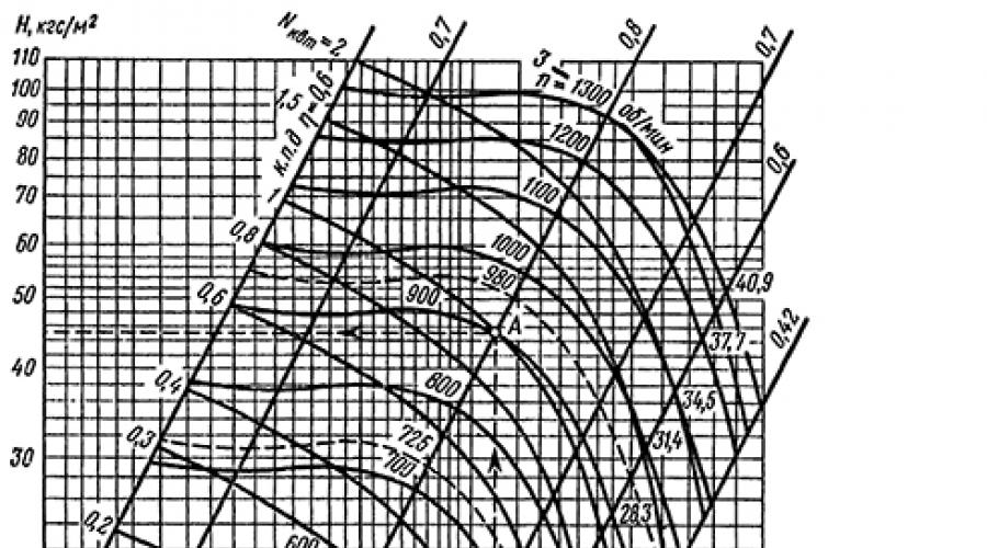
Knowing what performance and total pressure the fan should develop, the fan is selected according to its aerodynamic characteristics.
This fan characteristic graphically expresses the relationship between the main parameters - performance, pressure, power and efficiency at certain rotation speeds n, rpm. For example, you need to select a fan with a capacity of L = 6.5 thousand m3/h at P = 44 kgf/m2. For the selected centrifugal fan Ts4-70 No. 6, the required operating mode will correspond to point A (Fig. 8, a). From this point, the wheel rotation speed n - 900 rpm and efficiency η = 0.8 are found.
The most important relationship between pressure and performance is the so-called pressure characteristic of the fan P - L. If the network characteristic (dependence of resistance on air flow) is superimposed on this characteristic (Fig. 8, b), then the point of intersection of these curves (operating point) will determine the pressure and fan performance when operating on a given network. When the network resistance increases, which can happen, for example, when the filters become clogged, the operating point will shift upward and the fan will supply less air than necessary (L2< L1).
When choosing the type and number of centrifugal fans, it is necessary to be guided by the fact that the fan must have the highest efficiency, a relatively low rotation speed (u=πDn/60), and also that the wheel rotation speed allows connection to the electric motor at one shaft.

Rice. 8. Diagrams for calculating the ventilation network: a - aerodynamic characteristics of the fan; b - fan operation in the network
In cases where the operating fan does not provide the required performance, you can increase it, remembering that the fan performance is directly proportional to the speed of rotation of the wheel, the total pressure is the square of the rotation speed, and the power consumption is the cube of the rotation speed:

A type of centrifugal fans are the so-called diametrical fans (see Fig. 7, d). These fans have wide wheels and their performance is higher than that of centrifugal fans, but their efficiency is lower due to the occurrence of internal circulation flows.
The installed power of the electric motor for the fan (kW) is calculated using the formula

where L is the fan capacity, m3/h; P—full fan pressure, kgf/m2; ηv - fan efficiency (accepted according to
fan characteristics); ηп — efficiency of the drive, which with a flat belt drive is 0.9; with a V-belt - 0.95; when directly installing the wheel on the electric motor shaft - 1; when installing the wheel through a coupling - 0.98; k - safety factor (k = 1.05 1.5).
Ejectors are used in exhaust systems in cases where it is necessary to remove a very aggressive environment, dust capable of explosion not only from impact, but also from friction, or highly flammable and explosive gases (acetylene, ether, etc.).
The invention relates to the field of ventilation and can be used in the construction and reconstruction of chimneys, buildings, structures and premises. The method consists of introducing an air flow on the windward side of the pipe through specially made windows or holes in the walls of the pipe into the ventilation or chimney with the flow turning towards its cut, mixing it with the flow of sucked air and then removing both flows through the cut of the ventilation or a chimney and a window or opening on its leeward side. With the proposed method of creating thrust for more effective removal The extracted air uses the high-speed flow of wind energy. 3 ill.
The invention relates to the field of artificial (forced) ventilation and can be used in the creation and reconstruction of chimneys, buildings, structures and premises.
Mechanical ventilation with large volumes of air being moved and overcoming small resistances, in many cases it is irrational. It requires the installation of large fans, i.e. high initial costs, consumes a lot of energy and requires daily care behind you (M.A. Malakhov. Project of natural-mechanical ventilation of a residential building in Moscow. \\ ABOK-2003-No. 3). When creating traction in chimneys even fans do not always solve the task due to high temperature and smoke aggressiveness.
The desire to solve ventilation issues using natural wind energy led to the creation of air deflectors. These devices are installed on ventilation pipes in the area where they are blown by the wind, and they partially or completely replace mechanical fans. The simplest deflector is an ordinary section of a chimney or ventilation pipe open to the wind (Fig. 1). Its characteristics for suction are given in “Technical Notes of TsAGI No. 123, 1936, B.G. Musatov. Ventilation deflectors" Currently there are various designs deflectors, but they operate on the basis of one principle. It consists of using the suction effect of a wind jet, which entrains gas from the cut of the ventilation pipe due to turbulent friction.
This method of ventilation with the help of wind, taken as a prototype, consists of using a decrease in pressure (creating a vacuum) at the cut of the ventilation pipe while blowing a flow perpendicular to its axis. If the pipe section is equipped with some kind of head (umbrella, etc.), then the vacuum will change, but the principle remains the same. (V.P. Kharitonov. Natural ventilation with motivation. \\ ABOK-2006-No. 3, pp. 46-52). Existing methods ventilation of premises using wind energy only partially solves the dual problem of ventilation and the use of energy-saving technologies.
The most productive will be full use wind energy - the use of both high-speed pressure and bottom rarefaction that occurs in the wind shadow behind objects blown by the wind (in the so-called aerodynamic wake). With conventional deflectors on buildings, all wind directions are possible, and this makes the task much more difficult since the windward (windward) and leeward sides are uncertain and even change places.
The objective of the present invention is to modernize and intensify the process of removing sucked air through the use of both bottom rarefaction and high-speed wind pressure.
The technical result is an increase in the created vacuum, an increase in the flow rate of air or smoke sucked by the wind, and a decrease in the dimensions of ventilation systems.
The solution to the problem and the technical result are achieved by the fact that in the method of creating draft in ventilation and chimney pipes using wind energy, which includes the creation by the wind of a vacuum at the cut of the ventilation or chimney pipe, the air flow flowing onto the windward side of the pipe is introduced into the pipe through specially made windows or holes with the flow turning towards its cut, mix it with the flow of sucked air and then remove both flows through the cut of the pipe and windows or holes on its leeward side.
Figure 1 shows a diagram of the flow of sucked air and wind jets in and around a known ventilation or chimney pipe (in the prototype).
Figure 2 shows a diagram of the organization of the flow of sucked air and wind jets in the proposed method.
Figure 3 shows the distribution of relative static pressure around a circular ventilation pipe (cylinder) with air flowing transversely around it.
The flow diagram of sucked air and wind jets in and around ventilation or chimneys in known method, for example in the absence of a head, is shown in Fig.1. Here, the suction effect of the wind jet is directly used, entraining the sucked gas from the cut of the ventilation pipe 1.
Figure 2 shows a proposed diagram for organizing the flow of sucked air and wind jets in and around ventilation or chimneys. Incoming air is introduced into the part of the ventilation pipe 1 protruding into the wind zone through windows or holes 2 specially made in the pipe wall. At the same time, these inflowing jets are turned towards the pipe cut, for example, by special working surfaces (reflectors) 3. Next, these jets are completely or partially mixed with the sucked air. Due to the energy of wind jets, the pressure and flow rate of the sucked air increases. This mixture is then removed both through the cut of the pipe and through windows or holes on the leeward side of the pipe (due to low blood pressure here in the separated flow zone).
To confirm this possibility, figure 3 shows the distribution of the relative static pressure around a circular cylinder with air flowing transversely around it (from the book by P. Zhen. Separated flows. Translated from English, publishing house "Mir", Moscow, 1972, vol. 1 , p.27). In Fig.3, φ is the angle between the wind direction and the radius vector of a point on the cylinder (abscissa in the polar coordinate system); φ=0 - on the windward side, φ=180° - on the leeward side, in the zone of complete wind shadow. On the windward side at point φ=0, the static pressure exceeds atmospheric pressure in the undisturbed flow by velocity pressure =1. At φ=30° it decreases to atmospheric pressure ![]() , and already at φ=60° and further (up to φ=180°) it becomes significantly less than atmospheric pressure
, and already at φ=60° and further (up to φ=180°) it becomes significantly less than atmospheric pressure ![]() .
.
Physical basis The proposed new method of ventilation with the help of wind is the use of the process of additional ejection (suction) of the removed air by jets of wind introduced into the pipe. The incoming jets are first turned by reflectors from the initial direction perpendicular to the pipe axis to a direction close to the axial direction. Then they are mixed with the removed air, as a result of which the jets transfer their energy and momentum to the removed air, as in a conventional ejector, increasing the developed vacuum.
In addition, important in the proposed method is the process of removing the sucked air on the leeward side of the pipe through windows or holes similar to those through which air is introduced on the windward side. This significantly increases the consumption of removed air compared to when removal is carried out only through the cut of the ventilation pipe. The proposed method also approximately doubles the maximum vacuum achieved by the deflector.
A method of creating draft in ventilation and chimney pipes using wind energy, including the creation by the wind of a vacuum at the cut of the ventilation or chimney pipe, characterized in that the air flow flowing onto the windward side of the pipe through windows or holes specially made in the pipe wall is introduced into the pipe with a rotation of the flow towards its cut, mix it with the flow of sucked air and then remove both flows through the cut of the pipe and windows or holes on its leeward side.
Similar patents:
The invention relates to ventilation and air conditioning technology and can be used in natural duct ventilation buildings and structures for various purposes: residential, public, industrial, as well as cellars, basements, garages, etc.
The invention relates to energy and is aimed at eliminating the movement of aggressive and flue gases smoke exhausters and fans, especially in fire and explosion hazardous industries.
The invention relates to the design of industrial flare candle installations and can be used in the oil and gas, chemical and other industries for discharging permitted gases into the atmosphere. The proposed candle above the edge of the barrel 2 is equipped with a streamlined open-top collector of atmospheric precipitation 3. Precipitation from the collector 3 is structurally released by gravity beyond the dimensions of the edge of the candle barrel 2. An external protective shell 4 is provided around the edge of the barrel 2 and the collector 3, which protects the edge of the candle barrel 2 under the collector 3 from atmospheric precipitation coming from the wind at an angle to the vertical, and directs the exhaust gases upward into the atmosphere. The protective shell 4 has a height from below the edge of the spark plug to above the collector 3, and the gas outlet from above has an area less area the entry of precipitation into the collector 3. The invention is aimed at protecting the inner part of the candle from precipitation and for directing gas exhaust upwards, above the places where people stay. 2 ill.
The invention relates to devices used on chimneys from heat-generating equipment and on ventilation pipes. Using the device makes it possible to increase the height of rise of flue gases or air, which allows expanding the distribution area of substances emitted from the chimney, reducing their concentration per unit area and reducing pollution environment. The device contains a vertical pipe, a deflector in the form of concentric circular conical rings fastened with radial partitions, forming confusers along the height and circumference, a pipe installed at a distance of 10-30 cm from the outer surface of the pipe to form a gap and rigidly connected to the upper edge of the lower conical ring. There are 8 rectangular plates installed on the partitions perpendicular to the base of the deflector at an equal distance from each other. In the upper internal corners The partitions have hook-shaped ledges, and an additional flat ring is rigidly attached to each conical ring along the lower edge. The width of the first additional upper and lower flat rings is equal to the width of the rectangular plates, and a second additional conical ring is rigidly attached to the upper edge of each conical ring. 7 ill.
The invention relates to heating and ventilation - to devices for increasing traction, and can find application in household stoves for equipping chimneys and systems exhaust ventilation for equipping outlet pipes. The deflector contains a casing for protecting said pipe from atmospheric precipitation with an outlet for the product to be removed and means for attaching the casing to said pipe. The casing is mounted asymmetrically with the possibility of rotation on an axis associated with the mentioned means for its fastening. The deflector is equipped with an outlet head with an outlet for the product to be removed, and the casing is made in the form of a bent plate and is pushed onto the outlet head, covering it so that a passage is formed between them for air flow. The outlet head has a rigid connection with the casing, is mounted on the specified axis of the casing and faces the outlet hole for the removed product inside the casing. The technical result is the creation of conditions for the ejection of a product removed into the atmosphere. 5 salary, 5 ill.
The proposed technical solution relates to gas burner devices and can be used to burn fuel of any saturation level. The universal flare installation contains a cylindrical and coaxial base, a head with a plurality of side nozzle holes on its side surface and a casing located with a through radial gap around the head. In this case, the head and base are made in the form of a single part of the pipeline. The internal diameter of the head is larger than the internal diameter of the base, and in the upper part of the base there is a first divider with its nozzle holes for dividing the fuel flow into jets. The second divider is mounted movably along the axis of the pipeline, made in the form of a disk with at least four nozzle holes, one of which is located in the center of the disk and is the outlet of a gas equalizing tube installed inside the head to form an annular end hole in it, and forms a narrow end hole with the end of the head a gap, almost closing the end hole of the tip at low fuel pressure in the pipeline, the size of which increases due to the raising of the divider above the end of the tip as the pressure in the tip increases. The invention makes it possible to improve the quality of combustion of gas of any composition and to save high-quality fuel. 5 salary f-ly, 3 ill.
The invention relates to energy and can be used to regulate concentration toxic substances in gaseous waste emitted into the chimney. The installation for regulating the concentration of toxic substances in gaseous industrial wastes to MPC standards includes a chimney with a discharge hog equipped with a damper and a control gate, in which gaseous industrial wastes are mixed with the air entering it. The installation is equipped with a compressor, a compressed air pipeline, a draft activator made in the form of pipes with one plugged end and with one or two rows of holes along the pipes that lead into the openings of the chimney, and a mixer, at the outlet of which the concentration of toxic substances in the exhaust gas is not exceeds the maximum permissible concentration. The invention makes it possible to regulate the concentration of toxic substances by diluting exhaust gases compressed air, supplied to the chimney. 1 ill.
The invention relates to the field of ventilation and can be used in the construction and reconstruction of chimneys, buildings, structures and premises
METHODOLOGY FOR CALCULATING AN EJECTOR AIR DISTRIBUTOR FOR VENTILATION SYSTEMS OF ANIMAL PREMISES
M. M. ACHAPKIN, Candidate of Technical Sciences
It is well known that, from the point of view of technical and economic indicators, to ensure optimal microclimatic conditions in livestock buildings, the most acceptable are ventilation systems with air exchange controlled depending on changes in external meteorological conditions. However, the process of regulating air exchange taking into account design feature Traditional ventilation systems are a daunting engineering challenge.
Solving this problem is greatly simplified by using ventilation systems for supplying supply air concentrated jets into the upper zone of the room. In this case, an ejector air distributor (EA), which is a simple ejector, is used as a control device low pressure complete with inlet shaft (Fig. 1). Driving force the process of regulating the supply air is
Rice. 1. Schematic diagram operation of the ejector air distributor: 1 - nozzle; 2 - hole for intake air; 3 - mixing chamber; 4 - inlet shaft;
5 - throttle valve
The energy of the air flow leaving the nozzle is determined.
The essence of the calculation of any engineering and technical means, including electric power, lies, as is known, in determining its geometric characteristics to ensure the required parameters of the processed environment depending on the specified ones. In our case, in accordance with the theory of jet development in confined space the parameters of the supply air at the exit from the mixing chamber are specified. Thus, knowing the required air flow at the outlet of the EV and the area cross section livestock premises, using the formula presented in , you can determine the diameter of the mixing chamber (inlet pipe of the EV) ¿3:
where g^r ob is the maximum permissible
reverse air flow speed, m/s;
Lc - second air flow, m3/s;
cross-sectional area of the room, m2.
It is known that in ejectors of the movement of the sucked flow, the movement of flows in the mixing chamber, as well as their mixing, occurs due to kinetic energy flow of the working jet flowing out of the nozzle. Therefore, for normal operation The EV needs to create at the exit from the nozzle such a high-speed pressure P\y 12/2, the value of which would be
equal to (or exceeded) the sum of the required velocity pressure of the suction flow, the velocity pressure at
© M. M. Achapkin, 2001
exit from the mixing chamber, pressure losses in the suction air ducts DR2 and in the mixing chamber DR3,
Р3У3 2/2 + Ar2 + Ar3,
where y2, kt - air speed in characteristic sections of the air compressor, m/s;
Rb R2> Pb - air density in
characteristic sections, kg/m3.
Given the condition of equality of air densities in the characteristic sections of the EC (р\ - Р2 - Рз) and taking into account that the amount of air at the exit from the mixing chamber should be equal
the amount of air at the exit from the nozzle b\ and at the suction plane 1^2 z = A + ^2) > by simple transformations you can obtain an approximate value of the air speed at the exit from the nozzle:
Taking live section intake air flow /2 = ^з ~ and expressing the values of flow rates in characteristic sections through the corresponding velocities and their areas, we find:
In accordance with the data obtained on the theory of flow mixing, the air speed in characteristic sections is specified and the aerodynamic characteristics of the EV are calculated using well-known formulas, including pressure losses in the suction air vents DR2 and in the mixing chamber DR3.
It should be noted that the value optimal length It is more convenient to determine the mixing chambers for engineering calculations using the graph of the dependence of the degree of jet constraint and the length parameter of the mixing chamber obtained on the basis of experimental studies.
personal values of the installation mixing coefficient (3, shown in Fig. 2.
0,5 1,01,5 2,0 2,53,03,54,04,5 5,0 5,5
Rice. 2. Graph of natural values of x\ and *2 at different meanings coefficient
mixing
If the results of calculations confirm expression (2), taking into account a pressure reserve of about 10... 15%, then the calculation of the electrical energy can be considered complete.
The process of regulating air exchange is carried out by changing the amount of suction flow depending on the outside air temperature using the throttle valve of the supply shaft.
In accordance with the above, the essence of the methodology for calculating EV is as follows:
The required air exchange is determined at characteristic values of the outside air temperature from ¿„ax to
t1P and according to the formula /3 = b\ calculated
the required mixing ratio of the installation is determined;
Using formula (1), the diameter of the mixing chamber (supply pipe) is determined for the case of maximum air productivity of the installation;
The geometric and aerodynamic characteristics of the flows in the characteristic sections of the EV are determined. In this case, the air flow rate at the nozzle exit is assumed to be equal to the required air exchange at
The air exchange regulation process is calculated depending on the values outside temperature ranging from ¿„ah to
cooking equipment
air and its supply are selected to ensure the required air exchange
generally accepted methodology from the condition at
BIBLIOGRAPHICAL LIST
1. Bakharev V. A., Troyanovsky V. N. Fundamentals 2. Kamenev P. N. Heating and ventilation:
design and calculation of heating and ventilation - In 2 parts 4. 2. Ventilation. M.: Stroyizdat, 1966.
tions with concentrated air release. M.: 480 p. Profizdat, 1958. 216 p.
Received 12/25/2000.
SELECTION OF OPERATING MODES OF MACHINE AND TRACTOR UNITS USING COMPUTER EQUIPMENT
A. M. KARPOV, Candidate of Technical Sciences,
T. V. VASILIKINA, Candidate of Mathematical Sciences,
D. A. KARPOV, engineer,
A. V. KOZIN, engineer
It is known that all agricultural operations are carried out by machine-tractor units (MTA), which are a combination of an energy part, a transmission mechanism and working machine.
Every engineer knows how difficult it can be to select the right energy source and work (or work) machine to get high quality, maximum performance, smallest specific consumption And highest value coefficient of use of traction force on the hook, i.e., to make maximum use of the traction properties of a particular power tool.
Long time Such calculations were made manually, which required good engineering knowledge and considerable time.
Specialists had to complete the MTA based on the experience of the previous generation or using reference data. And if calculations were made, then according to a simplified
diagram that can be represented in the following form:
The range of possible speed conditions is set (for a given working machine);
The magnitude of traction force at selected speeds for given conditions is determined;
Calculated maximum width gripping the unit in selected gears;
The number of machines (or plow bodies) is determined based on the working width of the machine (or plow body);
The operating resistance is located;
The degree of tractor loading is calculated based on traction force.
Let us note that the value of the maximum hourly productivity is not determined and, moreover, it is not tested under production conditions. Such a calculation could not but lead to an erroneous decision. The problem of choosing the optimal energy source for the lowest energy intensity has been solved. At the department
© A. M. Karpov, T. V. Vasilkina, D. A. Karpov, A. V. Kozin, 2001
Usage: in the mining industry for ventilation of underground mines. The essence of the invention: the fan installation includes a fan placed in the ejector channel of the mine opening. The installation is equipped with a shell installed along the longitudinal axis of the mine opening, a jumper and an additional fan placed between the walls of the shell and the walls of the mine opening. The main fan is installed at the opposite end of the shell. Both fans are installed with a gap in relation to the walls of the shell with the output channels facing each other with the ability to move along the longitudinal axis of the shell. 1 ill.
The invention relates to fan engineering and is intended to provide ventilation for mining systems and ventilation systems. A fan installation is known that operates on a pipeline, for example, a mine ventilation network (Ushakov K.Z. Burchakov A.M. Puchkov L.A. Medvedev I.I. Aerology of mining enterprises, M. Nedra, 1987). Such fan installations include fans operating through a jumper. The disadvantage of the known fan installation is the incomplete use of the power of the drive motor for the purpose of a significant (2-3 times) increase in air flow compared to the rated performance of the fan installation, when the latter operates without a pipeline. A closer analogue to the claimed invention is a fan installation consisting of a fan-ejector installed in a mine working (Medvedev I.I. Ventilation of potash mines, M. Nedra, 1970, p. 124-139), which allows you to increase the air flow several times compared to nameplate performance. The disadvantage of the known technical solution is the possibility of operating an ejector located in a mine opening with a large cross-section in the “self-propelled” mode, i.e. with a closed movement of air flows in the area of the fan installation of circulating flows, as well as the difficulty in selecting the development of the desired configuration and in in the right place to achieve maximum ejection effect and expansion working area fan ejection unit. The purpose of the invention is to expand the working area (area of industrial use) of a fan ejection installation. This goal is achieved by placing two identical ejector fans at the inlet sections and the shell opposite each other with the possibility of moving the fans along the axis (closer or further to the shell) and covering the rest of the section of the mine working with a jumper. The cross-sectional dimensions of the shell are determined based on the optimal ratio of the cross-sectional area in the zone of complete movement of the primary flow passing through the fan and the secondary flow ejected along the cross-section between the fan and the shell. Due to this it is ensured constant flow air with the maximum ejection coefficient (relative to the nominal fan performance). The opening of the primary flow jet (to the zone of complete mixing of the primary and secondary flows) must occur in the shell, which prevents the movement of air flows inside the shell towards the main flow. To reduce the ejection effect from the maximum value, the fan is moved along the axis by moving it away from the shell or pushing it into the shell, as shown in the drawing. It is advisable to carry out this if it is necessary to reduce the amount of air supplied by the ejector installation in excess of the capacity control capabilities of the fan guide vane blades, i.e. there is an expansion of the working area towards a decrease in productivity. It is especially valuable that even for fans without means of performance control (guide vanes), it is possible to obtain a single characteristic and a working area, which expands the possibilities of using a fan ejector installation of the proposed type. The jumper between the shell and the walls of the mine opening will prevent the movement of air flows in this section. One of the ejector fans is in operation and, regardless of the size of the cross-section of the mine opening in which the fan unit is located, it will have a constant air flow. In reverse mode, the second ejector fan is turned on, located on the other side of the shell, opposite the first one. The performance of the fan installation in both direct and reverse modes will be the same. The drawing shows a fan installation, where there is 1 mine opening; 2, 3 ejector fans; 4 - shell; 5 jumper; 6 air flow during direct operation of the fan unit; 7 ejected flow in this mode of operation of the installation; 8 air flow during reverse operation of the fan unit; 9 ejected flow during reverse operating mode of the installation. The fan unit works as follows. When the ejector fan 2 is turned on, an air flow 6 passes through it, and along the cross section between outer surface fans 2 and inner surface shell 4 passes the flow of ejected air 7. Flow 6 and 7 moves along the length of the shell and enters the mine opening 1. This scheme allows the air flow to be increased several times compared to the nominal capacity of the fan. A jumper 5 is installed between the walls of the mine 1 and the shell 4, so no air movement occurs in this section. Shell 4 is selected in such a way as to ensure maximum ejection effect of air. If it is necessary to reduce the ejection effect beyond the control possibilities, fan 2(3) is moved along the axis (closer to the shell) shown by the dotted line in the drawing. On the other side of the shell, mirroring the fan-ejector 2, a fan-ejector 3 is installed, which is switched on in reverse mode, and the fan-ejector 2 stops in this case. In reverse mode, everything happens as when the ejector fan 2 is operating. Only in reverse side, namely, an air flow passes through the fan-ejector 3, and a flow of ejected air 9 passes along the cross-section between the outer surface of the fan-ejector 3 and the inner surface of the shell 4. Flows 8 and 9 are mixed along the length of the shell and enter the mine opening 1, ensuring the opposite air movement through the mining system, i.e. reversal of the air stream (regulation is similar to direct operation). Such a fan installation can be located in any mine opening where it is possible to place a shell, ensuring operation at any point in the extended working area in both direct and reverse operating modes. At the mine of the First Bereznikovsky industrial potash mine of Uralkali JSC, experimental work to test the proposed fan installation.
Claim
A fan ejector installation, including a fan placed in the ejector channel of a mine opening, characterized in that it is equipped with a shell installed along the longitudinal axis of the mine opening, placed between the walls of the shell and the walls of the mine opening by a jumper and an additional fan, with the main fan installed at the opposite end of the shell , both fans are installed with a gap in relation to the shell walls with the output channels facing each other with the ability to move along the longitudinal axis of the shell.