Installing drawer guides. Calculation of roller guides for a drawer. Marking and installation
Ball guides are actively used by furniture makers to pull out drawers. Ball guides are usually based on good quality iron, there are many modifications and there are also many manufacturers.
Ball guides so named because the movement of the components of the guides occurs due to metal balls, like in bearings. Durable steel balls move inside the profile, ensuring a stable easy glide boxes made of any material and any size, even under high loads.
The design of ball guides was invented by our Russian engineer Kulkov, so you can also find such a name as Kulkov guides. But the sale of such guides has been put on a commercial basis abroad.
Sliding baskets are installed on ball guides in sliding wardrobes, baskets for detergents. The pages of the site describe an interesting use of guides for pulling out original shoe racks in a sliding wardrobe.
In principle, ball guides also include Tandem guides from BLUM, which have been copied almost identically by many other hardware manufacturers.
In the article we will look at ball guides from GTV, a Polish brand, but recently they have been produced in China, it seems that the quality has not suffered much from this. GTV guides They are sold everywhere in the European part of Russia, their price is reasonable; closer to the East they most likely sell Chinese analogues.
Another name for ball guides that you may come across is telescopic guides.
GTV ball guides
17mm high ball guides for drawers
Guides with a height of 17 mm, length from 182 mm to 438 mm, support loads of up to 8-10 kg. Partial extension guides. The manufacturer recommends milling a groove 10 mm deep and 17 mm high on the side of the drawer. Perfect solution for use in chests of drawers. During installation, the guide assembly is attached to the side wall of the product, and then using screws to the side of the drawer.
Ball guides 27 mm high for drawers
Guides height 27 mm, length from 250 mm to 500 mm in increments of 50 mm, withstand a load of 15 kg. Unlike the first option, they are disassembled; milling a groove on the side wall of the box is not required. To calculate the dimensions of the box in width, you need to remove 22 mm from the width of the internal opening of the product.
Ball guides 35 mm high for drawers
Guides with a height of 35, lengths from 250 mm to 500 mm, can withstand a load of more than 20 kg, and there are options for full extension. In general, it resembles a 27 mm high guide.
Ball guides 45 mm high for drawers
Ball guides 45 mm high, the most common and actively used type of ball guides. There are different modifications with lengths from 250 to 700 mm. They can withstand heavy loads up to 36-38 kg.
The guides must be disconnected before installation; to do this, you need to raise or lower the black lever.
This disconnection system is found on most ball guides, including for baskets installed in cabinets in the kitchen.
The photo below shows a retractable basket for dishes with a fastening to the bottom turned upside down. We press the black lever and separate the basket from the guides, then there will be no problems with installing the basket.
To calculate the width dimensions of the box, it is necessary to subtract 26 mm from the internal width of the body, as for the roller guides.
They produce ball guides with a height of 45 mm of full and partial extension, with or without a closer. In addition, there is a ball guide system Push to open, that is, push to open, no handle is required to open the drawer. Reminds me of a system called TIP ON for Tandem Blum guides.
And the manufacturer Hettich has super-full extension ball guides.
Installation of ball guides
Let's look at the most common method for calculating ball guides, no program required.
We take our basic cabinet with a height of 720 mm excluding legs and a width of 600 mm with two fronts 356 m high, drawers 150 mm high. Boxes with a façade height of 356 mm can be made either 200 or 250 mm high, it all depends on yours or the customer’s wishes.
Ball guides usually attached to central axis side wall of the drawer, although some prefer to mount closer to the bottom edge of the side of the drawer.
We will carry out the calculation for the option of installing the guide along the axis of the side wall of the box. Let's draw a simple drawing, maybe by hand, as in the picture. Before marking, decide what the gaps between the facades will be; in our version, the gap between the facades will be 4 mm, and 2 mm at the top and bottom.
Drilling axis of the first ball guide= 2+34+75 = 111 mm, where:
- 2 – this is a gap of 2 mm from below (the facade is superimposed on a horizontal thickness of 16 mm by 14 mm, 2 mm remains)
- 75 is the middle of the side wall of the box, the total height of the box is 150 mm. If the bottom of the fiberboard box is overhead, then the height, including the fiberboard, will be 153 mm. But for calculations we still take 150 mm.
Drilling axis of the second ball guide= 2+356+4+34+75 = 471 mm, where:
- 2 – this is a gap of 2 mm from below 356 – the height of the lower facade
- 4 – gap between facades
- 34 – distance from the bottom edge of the facade to the bottom edge of the drawer
Horizontal axis of drilling the front wall of the drawer= 75 mm, we retreat 50 mm from the right and left edges of the front wall and get the coordinates for drilling the front wall.
Point along the X axis for screws on the facade= 34+75=109 mm, where:
- 34 – distance from the bottom edge of the facade to the bottom edge of the drawer
- 75 is the middle of the side wall of the box.
Point along the Y axis, for notches for screws for the right and left edges of the facade= 50+16+13+14 = 93 mm, where:
- 50 – indentations along the X axis from the edges when drilling the front wall of the drawer
- 16 – thickness of the side wall of the box
- 13 – clearance for installing a ball guide
- 14 – façade overlay side wall of the body (that is, there is a 2 mm gap between the edge of the side wall and the edge of the facade with a thickness of the side wall of the body of 16 mm).
Usually they don’t do any calculations, they simply drill four holes in the front wall of the drawer, measure the necessary indentations, place the drawer on the façade and screw in the first two self-tapping screws. They try it on, if it’s ok, then tighten the remaining two screws. No, they unscrew it, move it the required distance and check it again.
After the calculations, we move on to marking. We mark using a tape measure, an iron ruler, and a hard pencil. The places where the guides are attached using self-tapping screws are cored using a core punch or we make notches using an awl.
Ball guides
Home craftsmen often have to assemble furniture with their own hands. This happens both when purchasing ready-made interior items and when self-production cabinets, cabinets, tables and the like. Wherein correct fastening guides for a wide variety of drawers becomes a real stumbling block. Despite the apparent simplicity of this work, installation errors can lead to dire consequences. In progress further exploitation furniture may cause serious difficulties. Therefore, it is important to immediately determine the type of guides themselves and the method of their installation.
Types of guides
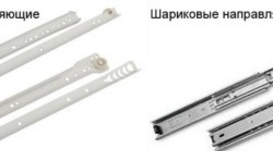
On this moment There are 2 main types of guides that are installed on a drawer. These are roller and ball systems. There are also other designs: hidden, with closers, telescopic, and so on. But they don’t install them with their own hands. This installation is carried out in a factory setting.
Roller guides usually consist of 2 strips with perforations for fasteners. Plastic wheels are attached to the ends of the structures. Thanks to them, the drawers slide out.

Figure 1. Types of guides.
Such systems have a number of significant disadvantages:
- When in use, the drawers make an unpleasant sound.
- The wheels are unreliable and quickly become unusable.
- If there is a strong pull, the box may fall out of its intended slot.
But such guides also have advantages. They are cheap and easy to install.
Ball systems are also called full extension guides. This is a telescopic design that allows you to extend the drawer the entire length of the bar. Inside the system there are metal balls that ensure smooth and almost silent movement.
The main difference between roller and ball systems is that the first one consists of 2 profiles independent from each other, and the second one is one-piece. In the first case, 1 strip is attached directly to the wall of the box, and the 2nd - to the furniture. The rollers are disassembled only during installation. And when assembled they look like a solid structure. It is this feature that ensures the reliability of the fastenings: the storage space does not fall out even with a strong tug. Appearance different guides are shown in Fig. 1.
At the moment you can find guides in stores different sizes. This allows you to select finished design to interior items of any type and depth. As a rule, roller systems are placed on boxes that are not expected to bear heavy loads. They can be found in linen and clothing closets, kitchen modules (for example, for storing cutlery), and hallways. Ball structures are placed on linen drawers of beds and furniture intended for children's rooms.
Return to contents
Installation of roller elements

Figure 2. Scheme of fastening roller guides.
Whatever type of drawer mounting you choose, you will need the following tools:
- drill with a thin wood drill bit;
- screwdriver with travel limiter;
- a set of screwdrivers with various blades (flat and Phillips).
Also, don't forget to have your measuring tools ready. You will need a tape measure or a long ruler and a square.
All necessary marks can be made with a simple pencil or colored chalk. The installation diagram of roller guides is shown in Fig. 2.
The process of installing guide systems on drawers occurs in 3 stages:
- Marking furniture walls and storage areas.
- Installing the bar on the drawer.
- Installing strips on furniture.

Figure 3. Diagram of the ball guides.
If you follow this sequence, you will be able to avoid possible mistakes.
The guide can be installed anywhere. But usually they are mounted strictly in the middle of the wall (this makes it easier to determine the location of the structure on the furniture) or flush with the top or bottom of the box. But roller systems are most often installed on the bottom edge.
It is wiser not only to mark the places for screwing in self-tapping screws, but also to drill them. This will ensure that the screw does not split the wood. You need to determine the location of the fasteners immediately both on the drawer and on the wall of the furniture.
The master should remember that the thickness of this type of guides is 1.25 cm. Accordingly, the width of the drawer should be 2.5 cm narrower than the internal width of the furniture (both sides are taken into account). Otherwise retractable design will not fit into the body. For freer movement, add 1-2 mm to this gap.
The length of the screws is selected based on the wall thickness.
The head of the fastener must firmly fix the guide, but not rise above the bar. In this case, the sting should not penetrate through the wall. First, the guides are fixed on the drawer, and then on the furniture. After which the storage system is placed in its designated place.
No matter how quickly progress progresses, the most popular today are telescopic or, as they are also called, full extension ball guides.
For those who don't know yet, they look like this:
Their advantages include:
- Relatively low cost;
- Smooth and most importantly quiet running throughout their entire service life;
- Ability to withstand significant loads;
- Excellent strength and wear resistance;
- Simplicity and ease of installation;
Guides of this kind are most often used as retractable mechanisms for chest of drawers, kitchen sections and many other mechanisms with which the owners do not want to have problems during their operation.
Calculation of drawer parts
In order to correctly install the full extension telescopic guides, you need to be sure that you have done the detailing of the drawer correctly.
An assembled box without a front installed on it means that between the box itself and the side of the product there should be a gap of 26 millimeters, that is, 13 millimeters on each side. These are the exact dimensions (13 millimeters) of the full extension telescopic guides.

The length (depth) of the box should be 6-10 millimeters longer than the guides, which, as a rule, have a length of 25 to 80 centimeters in increments of 5 centimeters. Thus, when installing the guides, place them in the middle of the drawer, leaving a minimum gap in front and behind the drawer. And also do not forget about a gap of at least 10 millimeters between the back wall of the drawer and the back wall of the product (chest of drawers).
The height of the box is usually made based on its purpose and the needs of its owners who will use it. But, as a rule, in the aisles from 8 to 25 centimeters.
Marking the attachment points for telescopic guides
The process of installing full extension telescopic guides is much simpler than it might seem to a person who is dealing with them for the first time, so to speak, for the first time picking them up.

When you take the telescopes in your hands, you can notice peculiar tendrils on it, usually black, so if you squeeze them and pull one half, it will disassemble into two parts, one of which is attached to the inner side of the chest of drawers, and the second to the side of the drawer.
By the way, you need to be extremely careful, since telescopes can be right-handed or left-handed and cannot be swapped.
Your main goal is to determine the exact mounting locations for the guides, secure each of the halves of the telescopes with three screws and carefully insert the drawer into the chest of drawers, thereby connecting the two parts of the telescopic guide into one whole.
Installation of ball telescopic guides
Making the markings drawer: horizontally, strictly in the center, on both sides of the drawer, draw a line with a pencil, and screw one of the halves of the guide along it, or rather the thinnest one (the one that goes inside the guide). Similarly, you need to mark the line along inside chest of drawers and screw on the telescopes.

The exact dimensions are indicated in or other product you are working on. Marking and installation must be done as shown in the figure below:

In our case, we mark 418 millimeters from the floor on one side, and mount the telescope at this height. We make markings in the same way and fix the telescope on the second side of the chest of drawers.


Well, that's all hard work finished, then strictly along the marked line we screw the halves of the guide to the sides of the chest of drawers and the drawer, after which you can move the drawer into place. All that remains is to install furniture facades on the drawers and the chest of drawers is ready.
Let's move on today to a higher quality, in my opinion, than roller guides, retraction system - ball guides.
Let's look at the installation using the example of assembling a kind of sideboard for the kitchen with four drawers.
Calculations of parameters for drawers are not very different from rollers.
The width of the box is equal to the internal width of the box minus 25 mm.
The depth of the drawer, as a rule, corresponds to the length of the guides themselves, but it can be larger (in this case, the drawer will not extend completely.
Example: let’s calculate the parameters of a chest of drawers 600 mm wide and 500 mm deep
Width = 600-32-25=543 mm (32 mm is the thickness of the racks 16 mm, and 25 mm is the sum of the thickness of the guides in mm)
The depth of the box will be 450 mm (since it is standard size guide, and up to back wall the box should not reach a couple of centimeters).
That is, the fronts of the drawers (inset) will be 543-32 mm = 511 mm
The side walls of the boxes will be 450 mm.
The bottom of the box (DVPO) will be 450x543 mm
So, let's order cutting laminated chipboard, that is, at the output we get 5 parts for each box of given sizes (parts from laminated chipboard are edged along the length on one side). Plus the facade depends on the size of the box.
At the ends (in the center) of the fronts, holes are drilled for confirmations (one or two - in in this case- one). Opposite them in the face of the side walls, 8 mm from the edge, through holes of 7-8 mm are drilled - for the caps of the confirmations.
Now let's immediately make the markings. On the side posts of the box (to which the boxes will be attached), we first mark the boundaries of the facades with gaps between them (2 mm each). Then we mark the axis of the guide, first on the side wall - for example, we retreat 10 mm from the bottom. And then on the counter - so that the box does not protrude from behind the facade, it must be made a little higher, that is, we retreat 20 mm from the lower edge of the facade. 
On these axes we set aside 37 mm - the center of the mounting hole in the guide.
After this, we disassemble the guides into two elements. 
For those who do not know how this is done, I have prepared the following slide - you need to slide the plastic clamp (up in the photo), after which both components of the guides can be easily separated. 
On the side walls - on the axis of the guides, we use an awl to prick the centers of the mounting holes. 
We fix these components on the walls of the boxes. 
We direct the second (larger) half onto the walls - taking into account the holes previously marked and pinned with an awl. 
We assemble the chest of drawers itself (in our case it is a sideboard). 
We proceed to assembling the box: we tighten the walls into pre-drilled holes. 
We check the perpendicularity of the walls of the box using a carpenter's square. 
We secure these results by fastening the bottom from DVPO - this should be done using self-tapping screws with a pitch of at least 150 mm. I use 25mm screws. 
All that remains is to install assembled boxes onto the guides into the furniture box and you can start fixing the facade (I already wrote about how to do this earlier -). 
Many novice craftsmen who decide to assemble furniture with their own hands are intimidated by self installation drawers. In fact, there is nothing complicated about it. And there is no need to first draw up any additive maps or do complex mathematical calculations. In my experience working in manufacturing, I only knew one assembler who meticulously calculated everything down to the millimeter before installing drawer slides. Everything else was done “by eye”, observing only the elementary rules of geometry. And it “worked” no worse.
What you need to know before you start installing drawers
The principle of attaching the runners to the sides of the cabinet is the same for almost all retractable systems. As a rule, 2 mm are removed from the front edge and then screwed along the outer mounting holes and several central ones, depending on the size of the guides themselves.
The only difference is the calculation of the height at which the skids are mounted.
There are three main types of drawer slides, with different slide positions:
- Along the bottom edge (bottom). The simplest and most cost-effective roller guides are installed strictly under the bottom of the drawer frame itself, overlapping on the fiberboard. As in fact, the most expensive options for equipping drawers are tandem boxes. They are also installed on the lower level of the drawer frame.
- In the center of the side of the box. Ball telescopic ones give greater freedom during installation - they can be mounted at any level of the sidewall of the box box. But it’s still better to stay at the central one. As practice shows, installation and adjustment are greatly simplified.
- With top mount. For metaboxes (metalboxes), the roller guide runners are located along the upper level.
In each case, the box will “sit” completely differently. Let's look at the example of a drawing of a regular chest of drawers with three drawers. To make the task easier, let’s assume that the boxes begin to be installed from the bottom of the side of the cabinet itself, without deduction for the base box and bottom. This is possible in the following option.

- The height of the sides of the cabinet is 668 mm (with the height of the chest of drawers without legs being 700 mm).
- The height of the drawers is 150 mm with the height of the facades being 221 mm.
How to install roller guides
The bottom is captured by part of the runners that are attached to the box at a height of 8-10 mm, depending on the thickness of the bottom (fibreboard).
Let's take the distance from the bottom to the lower edge of the facade to be 20 mm (usually it ranges from 10-30 mm).
The installation diagram of the roller guides will look like this.

There will be no harm in rounding the values. Take not the height level 32/255/478, but round for convenience to 40/260/280. The main thing is to secure the roller guides equally on both sides.
How to install ball guides
With a similar tolerance under the bottom of 20 mm, the installation diagram of the ball guides will look like this.

The difference is that it is customary to install ball guides in the center of the sidewall. Because they happen different widths, it’s easier not to move them higher or lower.
Also, the values 99/322/545 can be rounded and made, say, 100/330/550.
How to install metaboxes on a drawer
A distinctive feature of a drawer with metal sides is its fastening along the top edge. The main thing here is to choose the right height of the metaboxes relative to the vertical of the facade. It can be 54 mm (optimal for installation in narrow niche under the built-in oven in the kitchen), 86, 118 or 150 mm. If a deeper drawer is required, it can be “expanded” using one or two rows of special rails.
In our case, it is optimal to take a 150 mm metabox; the installation diagram will look like this.

As in previous versions, rounding is acceptable for convenience: instead of 134/357/580, it is quite possible to take 130/360/580.
How to install fronts on a drawer
Fronts on drawers are always installed after “testing” and alignment of the inner box.
First you need to make sure that the box moves freely and smoothly, does not warp during movement and does not jam.
Only then, with the help of special linings (chipboard scraps, a wooden or plastic ruler will do), is the uniform position of the facades pretended.
Then, using double sided tape The facade is fixed and attached from the inside using 4x30 self-tapping screws. The through fastening of the handle also “holds” the facade. But it is worth drilling for the handle only after the facade is securely fixed.
How to avoid installation errors
If the guide rails themselves are screwed at the same level, strictly opposite each other, and the drawer does not warp in any way during the extension process, then everything will “work” well.
This is the main rule in installing any box - maintain alignment.
The second rule is the need to correlate the height of the sides of the box itself with the height of the facades. Before you start “distributing” them in height. I recommend immediately making marks with a pencil on the end of the body, noting the position of the facades, in order to have a visual representation.

The main pitfall is the irrational distribution of the guides in terms of the useful volume of the box itself.
For example, in the photo, the drawers in the pencil case function absolutely normally.

But due to the fact that the top drawer was “lifted up” too high, its capacity was greatly reduced. It would seem that the middle drawer is more spacious. But no. The lower edge of the front of the top drawer “does not allow” the middle drawer to be loaded along the entire height of the resulting niche.
In fact, this point is not critical. And if you don’t highlight it, the owner himself won’t even notice. But the one who did it will definitely remember that it would have been better differently.
Step-by-step instructions for installing a drawer
Before installing the drawer slides, you must determine the correct position of the fasteners. Calculations are the first step in installation.
 Step 1 - determining the position of the drawers inside the cabinet

The greater the difference between the height of the front and the height of the sides of the drawer, the larger the gap should be. This is done for reasons of stability of fastening: after all, the facade is attached to the sides of the box itself and the fastening points should be close to the center.
The remaining distance is evenly distributed between the remaining boxes. Moreover, it is customary to leave the same amount on the bottom of the box as was given on the bottom.
Such calculations are simple. Distances can be calculated using a calculator or drawn to scale. Many assemblers estimate directly on the body, measuring from point to point with a tape measure.
When the position of the boxes is determined, the attachment points for the runners are drawn. Depending on the drawer system, this may be the center, bottom or top edge of the drawer side.
After the calculations, begin installing the drawer guides. This will be the second step in installation.
 Step 2 - attaching drawer guides inside the cabinet
Strictly opposite each other outer part the runners are attached to the sides of the cabinet, and the inner ones are attached to the drawers themselves (the exception is metaboxes, in which the internal guides are already built into the assembled drawers).
Then they try to push the boxes of drawers inside the cabinet and adjust them so as to achieve smooth and uniform movement.
 Step 3 - Adjustment smooth running drawer guides inside the cabinet
Then they begin to install the facades. But first, uniform gaps between them are measured using available material - various linings of the required thickness.
 Step 4 - setting uniform gaps on the facades
 Step 5 - preliminary fixation of the facades with double-sided tape
And they are pulled from the inside using self-tapping screws.