Widening the gauge and raising the outer rail in curves. Rail track arrangement
Track width – 1520 mm. Permissible deviations are +8 and -4 mm, and in areas where the speed limit is 50 km/h or less - no more than +10 and -4 mm. On roads all over the world, the operational length of which is about 1200 thousand km, about 30 track width dimensions. It is generally accepted that the track width is 1435 (1430) mm normal - it makes up 62% of the world's length of the road network, more of it - wide and less of it - narrow gauge. After a track with a width of 1435 mm, the most common track sizes are 1675, 1524 (1520 mm), 1067 mm, 1000 mm. Other track widths together amount to about 5%.
Peculiarities rail gauge in curves. Rail gauge width in curves.
Widening of the rail track for radii less than 350m.
An elevation is established along the outer rail track at a curve
Straight sections with circular curves are connected by transition curves. Transition curves are also arranged between curves of different radii.
Shortened rails are laid along the curved internal rail thread to ensure that the joints are located opposite each other.
In curved sections of the track on double-track lines, widened inter-tracks are installed. Broadening is carried out within the transition curves.
The widening or width of the track in the curve is determined by calculating the fit of railway carriages into the curve, based on the following two conditions:
The track width should be optimal, i.e. provide the least resistance to the movement of trains, the least wear of rails and wheels, protect the rails and wheels from damage and the path from distortion in plan, and prevent the wheels from falling between the rail threads.
The track width should not be less than the minimum permissible, i.e. should prevent jamming of the carriages' undercarriages between the outer and inner rail threads.
Definition optimal width ruts in a curve.
In all cases, the calculated rail gauge width should not exceed maximum width gauge S max = 1535mm.
If the calculated track width S receives a value greater than the maximum value S max, you should proceed to determine the minimum permissible track width by adopting the appropriate design scheme.
If the calculated track width S turns out to be less than the normal width on a straight section of the track (S 0 = 1520 mm), then this will mean that the design dimensions and features of the undercarriage of the vehicle in question allow it to pass a curve of a given radius without widening its track. In this case, the track width S should be taken according to the PTE depending on the radius.
Determination of the minimum permissible track width.
S min = q max = T max + 2h max + 2µ (5)
When determining the minimum permissible track width, the following cases are possible:
If S min ≤ S pte, then inclusion is ensured. At the same time, comparing all three track width values S min , S pte and S opt with each other allows us to roughly estimate the conditions under which actual fitting will take place, i.e. what type of fit it will be closer to, free or wedged.
If S min > S pte, then this case in turn splits into the following two:
If S min the wheels fall into the track, then to allow the crew in question to pass, the track must be rebuilt from the size S pte to the calculated value S min (according to permission H).
If S min S max , then to allow the crew to pass, the track must be changed by the calculated value; at the same time, to prevent the wheels from falling inside the track, counter rails are laid.
Elevation of the outer rail, based on the characteristics of equal vertical wear on both rails.
To avoid these phenomena, the outer rail thread is raised above the inner one.
To ensure equal vertical wear on both threads, it is necessary that the sum normal pressure from all trains on the outer thread was equal to the sum of normal pressures from the same trains on the inner thread
Therefore it is necessary that:
ΣE n = ΣE in
The centrifugal force when a vehicle of mass m moves along a curve of radius R with a speed V will be determined by the expression:
Where G is the weight of the crew
Elevation of the outer rail, based on ensuring passenger comfort.
From (25)
Here and nd – permissible value unsuppressed centrifugal acceleration. According to the standards, a and nd is assumed to be equal to passenger trains 0.7 m/s 2 (in some cases a an = 1.0 m/s 2), and for freight trains a nd = ±0.3 m/s 2.
Taking S1 = 1.6 m, g = 9.81 m/s 2 , V – km/h, h – mm, we obtain:
163a nd (26)
The maximum height of the outer rail on domestic roads is taken to be 150 mm. If the calculation results in a large value, take 150 mm and limit the speed of movement along the curve from equation (26)
With a nd = 0.7 m\s 2 and h = 150mm
External rail elevation standards.
For passenger trains
For freight trains
For train flow
Where, V max p and V max gr – maximum speeds respectively, passenger and freight trains, established by order of the head of the road.
V pr is the average superficial speed of the flow trains.
R – radius of the curve.
When determining the elevation using formula (29), rational track operation is ensured at freight train flow speeds lying within
Which corresponds to the level of outstanding accelerations of passenger trains a np = 0.7 m/s 2 and freight trains a n gr = ±0.3 m/s 2 .
Basic requirements for the design and content of transition curves.

Within the transition curve, the elevation of the outer rail gradually increases from 0 to h in the CPC; a deduction is made for the widening of the track, if the latter is present in the circular curve.
The main requirements for the design and content of the PC are that the appearing, developing and disappearing force factors (accelerations, forces, moments) within the length R of the PC change gradually and monotonically, with a given schedule, and at the beginning and end of the PC they are equal zero, which is ensured if the requirements are met.
In the NPC y,φ and k = 0, the CPC these parameters are not limited.
In NPC and CPC these derivatives are equal to zero.
The first three requirements about the inadmissibility of sudden changes in the NPC, CPC and throughout the transition curve (Fig. 2) ordinates at, turning angles φ and curvature To by the monotony of their changes. Fulfilling all five requirements creates best conditions passage of rolling stock along curves, which is especially important when high speeds movements.
Physical parameter of the transition curve.
At l = l 0 in the CCP ρ= R And
(6)
Here C is the (geometric) parameter of the transition curve.
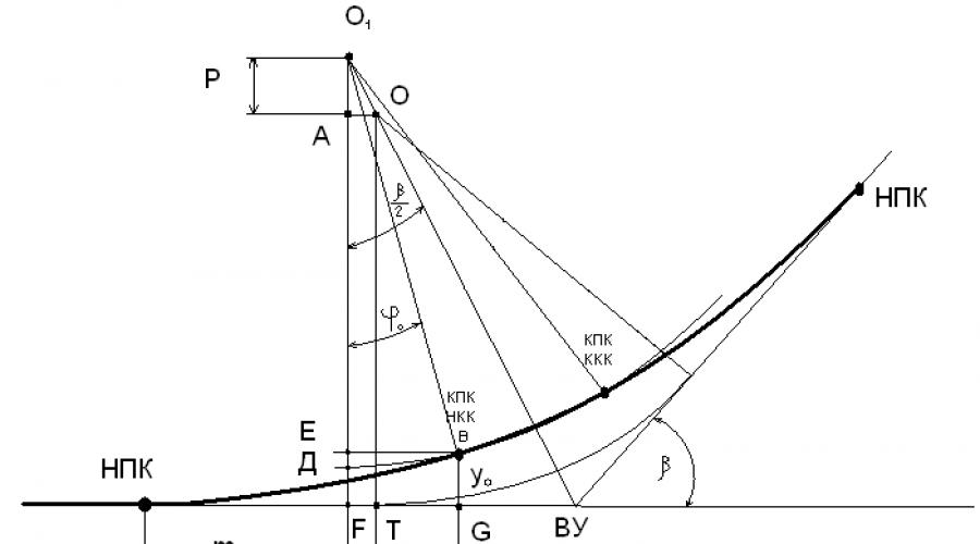
Design of transition curves using the displacement method.
FT = AO = Ptg β/2
Where
m 0 = m + Ptg β/2
The unknown quantities m and P are determined as:
Knowing the position of the beginning of the transition curve of the NPC, the coordinates of its end (X 0,y 0) at the point of the CPC are calculated using the equation of the radio-distance spiral in parametric form
Shortened rails on the inner thread.
For each curve, the type of shortening, the number and order of laying the shortened rails are selected. There are two types of shortenings for P65 rails: 80mm and 160mm.
The choice of the type of shortened rails for a given curve is made according to the formula:
Where S 1 is the track width along the axis of the rail head within the circular curve:
S pte – standard track width in curves depending on the radius;
Having calculated the value of shortening using formula (1), we accept the nearest larger standard shortening. Required amount shortened rails of the accepted size are determined from the expression:
Shortened rails are laid in those places of the curve where the accumulated run of the joints reaches half of the accepted standard shortening.
Widening track distances in curves.
This increase is carried out different ways. One of the methods is to increase the track distance from 4.1 m to 4.1 + A 0 on straight lines before each transition curve by introducing additional S-shaped curves.
This method is rarely used, since it has a major drawback: on the path being moved, two curves appear on each side of the main curve, albeit of a large radius. Another method (the method of different shifts) is to use different parameters From the transitional curves of the outer path. Satisfied in the usual way, parameter C of the transition curve of the internal path is selected in such a way that the shift of the internal circular curve P in is equal to the shift of the circular curve of the external path plus A 0, i.e.
R in = R n + A 0
Classification of connections and path intersections.
|
Connections and intersections |
|||
|
Turnouts |
Blind intersections |
Path connections |
Rotating devices |
|
Singles |
Rectangular |
Switch streets |
Triangles |
|
Double |
Oblique |
Conventions |
Loops |
|
Cross |
Curvilinear |
Plexus |
Circles |
|
Combined | |||
Classification of turnouts and blind intersections.
Singles
One-way ordinary (most common on the road network and most often used on main and station tracks)
Versatile symmetrical
Asymmetrical one-sided curvature
Double
Unilateral
Versatile symmetrical
Versatile asymmetrical
Cross
Singles
Double
Combined
When combining two tracks of different sizes
When weaving turnouts
Basic elements of ordinary turnouts.
The main elements of an ordinary single turnout include:
Arrow
Crosspiece with counter rails and track counter rails.
Connecting paths
Under-rail bases
Transfer mechanism and its fittings

Design features of turnouts and requirements for them
Turnouts are key track structures for increasing train speeds and increasing freight capacity. bandwidth railways. Research has shown that without the presence of turnouts that allow the speed set on the stretch to be realized, it is practically impossible to solve the problem of increasing the speed on the section as a whole, and on the stretch in particular.
Definition of main geometric dimensions ordinary turnouts with a straight point.
Determine the radius of the transfer curve R.
Length of direct insertion k in front of the mathematical center of the cross
Theoretical L T translation length
Practical L P transfer length.
Axial dimensions of translation A And b.
n- length of the front – mustache – part of the cross
m– length of the tail part of the cross
O k – mathematical center or point of the cross
S 0 – normal track width
l sharp – wit length
β – arrow angle
q – front frame rail overhang
L T - theoretical length of the switch - the distance from the beginning of the points to the mathematical center of the cross, measured along the working edge of the frame rail or along the axis of the straight track.
O c – center of the turnout – intersection of the axes of the direct and side tracks
a – distance from the front joint of the frame rails to the center of the switch, measured along the axis of the straight track
b – distance from the center of the S.P. to the tail joint of the cross, measured along the axis of any translation path.
O – center of the conversion curve
L P – total or practical length of S.P. from the front joint of the frame rails to the tail joint of the cross.
Let us take the Y-Y axis in a rectangular coordinate system, passing through the mathematical center of the cross, and X-X axis compatible with the working edge of the outer thread of the straight path.
Let's project the ABCO K contour onto these mutually perpendicular axes. But first for this we will make the following additional constructions.
From the center of the conversion curve, i.e. from point O, restore the radius - perpendicular to the working edge of the frame rail; From points B and C we lower perpendiculars to this radius - the perpendicular at points B 1 and C 1, respectively. What will happen as a result right triangle OB 1 B with a right angle β at the vertex O, as well as OS 1 With a right angle at the vertex C 1 and with a cross angle α at the vertex O.
Theoretical transfer length , as can be seen from the figure, is a projection of the ABCO K contour onto the horizontal axis, i.e.
(1)
But B 2 C = C 1 C – B 2 C 1 = C 1 C – B 1 B
From triangle OS 1 C: WITH 1 C =R sinα
From triangle OB 1 B: IN 1 B =R sin
From triangle O to C 2 C: WITH 2 ABOUT TO = k cosα
Therefore, after substituting the values of B 2 C and C 2 O K into equation (1), we obtain:
L T = l sharp withsβ + R (sinα - sinβ )+ k cosα (2)
The projection of the same ABCO K contour onto the vertical axis will be the normal track width against the crosspiece, i.e.
S 0 = l sharp sinβ + B 1 WITH 1 + SS 2 (3)
But B 1 C 1 = OB 1 - OS 1
From triangle OB 1 B: OB 1 = R cosβ
From triangle OS 1 C: OS 1 = R cosα
From triangle O K C 2 C: SS 2 = k sinα
Thus, substituting the values B 1 C 1 and СС 2 into expression (3), we find the track width in the cross: S 0 = l sharp sinβ + R (cosβ - cosα ) + k sinα
Total or practical length of the turnout: L P = q + L T + m (5)
The radius R and the length of the straight insert in front of the cross k are determined depending on what parameters are known or specified.
GENERAL INFORMATION. DEVICE OF Rail Track. The design of the rail track is closely related to the design and dimensions of the wheel pairs of the rolling stock. The wheelset consists of a steel axle on which wheels are tightly mounted, having guide ridges to prevent derailment. The rolling surface of rolling stock wheels in the middle part has a 1/20 conicity, which provides more uniform wear, greater resistance to horizontal forces directed across the track, less sensitivity to its malfunctions and prevents the appearance of a groove on the rolling surface, which makes it difficult for wheelsets to pass along turnouts . In accordance with this, the rails are also installed with a 1/20 inclination, which, with wooden sleepers, is achieved through wedge linings, and with reinforced concrete ones, by a corresponding inclination of the surface of the sleepers in the area where the rails support. The distance between the inner edges of the rail heads is called track width . This width consists of the distance between the wheels (1440±3 mm), two thicknesses of the ridges (from 25 to 33 mm) and the gaps between the wheels and rails necessary for the free passage of wheel pairs. The width of the normal (wide) gauge in straight and curved sections of the track with a radius of more than 349 m is adopted in the USSR as 1520 mm with tolerances for the widening side of 6 mm and for the narrowing side of 4 mm. In accordance with the PTE, the top of the rail heads of both lines of track on straight sections must be at the same level. It is allowed to contain one rail thread 6 mm higher than the other on straight sections of the track over the entire length of each of them. When constructing a track, the joints on both rail threads are placed exactly opposite each other along a square, which, compared to the placement of joints staggered, reduces the number of impacts of wheel pairs on the rails, and also allows you to prepare and change the rail and sleeper lattice in whole links using track layers. In order to prevent each wheel pair from rotating around a vertical axis, the wheel pairs of a car or locomotive are connected by two or more rigid frames. The distance between the extreme axles connected by the frame is called the rigid base, and between the extreme axles of a carriage or locomotive is called the full wheelbase. The rigid connection of the wheel pairs ensures their stable position on the rails, but at the same time makes it difficult to pass in small radius curves, where they may jam. To make it easier to fit into curves, modern rolling stock is produced on separate bogies with small rigid bases.
FEATURES OF PATH CONSTRUCTION IN CURVES. In curved sections, the track design has a number of features, the main of which are: the elevation of the outer rail above the inner, the presence of transitional curves, widening of the track at small radii, laying of shortened rails on the inner rail thread, strengthening of the tracks, increasing the distance between the axes of the tracks on two - and multi-track lines. Elevation of outer rail is provided for a curve radius of 4000 m or less so that the load on each rail thread is approximately the same, taking into account the action of centrifugal force. The device transition curves is associated with the need for a smooth coupling of the curve with the adjacent straight line, both in plan and in profile. The transition curve in plan is a curve of variable radius, decreasing from infinitely large to R - the radius of a circular curve with decreasing curvature is proportional to the change in length. Widening gauges are made to ensure that the rolling stock fits into curves. Since the wheel pairs are fixed in the bogie frame in such a way that they are always parallel to each other within the rigid base, in a curve only one wheel pair can be located along the radius, and the rest will be at an angle. This necessitates increasing the gap between the wheel flanges and the rails in order to avoid jamming of the wheel pairs.
Laying shortened rails into the internal thread is necessary to prevent the joints from running apart. Since the inner rail thread in the curve is shorter than the outer one, laying rails of the same length in it as in the outer one will cause the joints to run forward on the inner thread. To eliminate the spread of joints at each curve radius, it is necessary to have its own amount of rail shortening. For unification purposes, standard shortenings of 25 m long rail links by 80 and 160 mm are used. The laying of shortened rails in the inner thread is alternated with the laying of rails of normal length so that the run of the joints does not exceed half the shortening, i.e. 40; 80 mm. Gain paths in curves are made at R ≤ 1200 m to ensure the necessary equal strength with adjacent straight lines. To do this, increase the number of sleepers per kilometer, widen the ballast prism on the outer side of the curve, install asymmetrical pads with a large shoulder on the outer side, and select the hardest rails. In circular curves on double- and multi-track lines, the distance between the track axes increases in accordance with the size requirements, which is achieved within the transition curve of the internal track by changing its parameter .
PATH DEVICEON BRIDGES AND IN TUNNELS. The track design on bridges and tunnels has a number of features. On metal bridges, the track is usually made without ballast; on wooden beams laid at a distance of 10-15 cm from each other. The beams are bolted to the longitudinal beams. To hold; rolling stock in case of derailment on existing bridges there are wooden guard bars outside the track, and counter rails inside . On bridges under construction, metal security corners of a special profile are used for this purpose. . On bridges with large metal spans, the track is laid on metal crossbars. On a number of metal bridges and, in particular, on the bridge over the river. Amur on BAM uses a track design on solid reinforced concrete slabs , which reduces the cost of maintaining the bridge deck. On stone, concrete and reinforced concrete bridges, as well as on overpasses located within the station, the track is built on crushed stone ballast and ordinary sleepers, for which purpose a trough is installed on the bridge with a width at the top on single-track lines of at least 3, 6 m, and on double-track - at least 7.7 m. The thickness of crushed stone ballast on bridges and overpasses is, as a rule, no less than 25 cm. On approaches to bridges, regardless of the type of ballast accepted on a given line, the track on both sides is laid on crushed stone ballast, which increases track stability and reduces dust contamination of bridge structures when trains move. On the approaches to ballastless bridges, the track is completely secured against theft; On the bridges themselves, anti-theft devices are installed as an exception. On large metal bridges, in order to avoid rupture of joints during temperature changes in the length of the spans, special devices are installed that ensure mutual displacement of the point and frame rail. It is recommended to make the path in the tunnels on reinforced concrete sleepers with a diagram one step higher than on the approaches. For a length of 200 m on each side in front of the tunnel and in the tunnel itself, the path must be on crushed stone ballast with a thickness of at least 25 cm. The path in the tunnel can also be on hard concrete base with separate type fastenings with shock absorber gaskets. Use on bridges and tunnels is not permitted. different types rails, transition joints and rail cabins.
21 22 24 ..Construction of rail tracks in straight sections of track
A rail track is two rail threads installed at a certain distance from one another and attached to sleepers, beams or slabs. The design and maintenance of the rail track depend on the design features of the running parts of the rolling stock.
These include the presence of flanges (ridges) on the wheels, which hold the wheels on the rails and direct the movement of locomotives and cars. The wheels are tightly pressed onto the axle and form a wheel pair together with it. The axles of the wheel pairs, united by a common rigid frame, always remain mutually parallel.
The rolling surface of the wheels is not cylindrical, but conical, with a slope in the middle part of 1:20.
The distance between the inner edges of the wheels is called the nozzle T = 1440 mm with maximum tolerances+ - 3 mm. The distance between the extreme axles fixed in the frame of one cart is called the rigid base.
The distance between the outer axles of a car or locomotive is called the full wheelbase of that unit.
Thus, the total wheelbase of the BJT-8 electric locomotive is 24.2 m, the rigid wheelbase is 3.2 m.
The distance between the working edges of the wheel flanges is called the width of the wheelset.
The thickness of the wheel flanges must be no more than 33 mm and no less than 25 mm. In order for the wheelset with the widest nozzle and unworn wheel flanges to fit inside the track, its width must be 1440 + 3 + 2 x 33 = 1509 mm, but in this case the wheelset will be clamped (jammed) between the rails.
The track width is the distance between the inner edges of the rail heads, measured at a level of 13 mm below the rolling surface. The track width on straight sections of the track and in curves with a radius of 350 m or more should be 1520 mm. On existing lines, until they are transferred to a 1520 mm gauge, a track width of 1524 mm is allowed on straight sections and in curves with a radius of more than 650 m. In curves of smaller radius, the track width increases in accordance with the Technical Operation Rules.
Tolerances for track width are set for widening plus 8 mm, for narrowing of the track minus 4 mm, and in areas where speeds are set at 50 km/h or less, tolerances of +10 for widening are allowed - 4 for narrowing. Within tolerances, the track width should change smoothly.
Rail bending. In straight sections of the track, the rails are not installed vertically, but with an inclination into the track, i.e., with a cushion to transmit pressure from the bevel wheels along the axis of the rail. The conicity of the wheels is due to the fact that rolling stock with such wheel pairs offers much greater resistance to horizontal forces directed across the track than cylindrical wheels, and the “wobble” of the rolling stock and sensitivity to track faults are reduced.
Variable conicity of the wheel rolling surface from 1:20 to 1:7 is given to avoid the appearance of grooved wear of the wheels and for a smooth transition from one track to another through the turnout. The rail threads must be at the same level. Permissible deviations from the norm depend on the speed of trains.
On long straight lines it is allowed to keep one rail thread constantly 6 mm higher than the other. With this position of the rail threads, the wheels will be slightly pressed against the lowered straightening thread and move more smoothly. On double-track sections, the straightening thread is an inter-track thread, and on single-track sections, as a rule, it is the right thread along the kilometers.
The design of the rail track is closely related to the design and dimensions of the wheel pairs of the rolling stock. The wheel pair consists of a steel axle on which wheels are tightly mounted, having guide ridges to prevent derailment (Fig. 2.12). The rolling surface of rolling stock wheels in the middle part has a 1/20 conicity, which provides more uniform wear, greater resistance to horizontal forces directed across the track, less sensitivity to its malfunctions and prevents the appearance of a groove on the rolling surface, which impedes passage. wheelsets along turnouts. In accordance with this, the rails are also installed with a 1/20 inclination, which for wooden sleepers is achieved through wedge linings, and for reinforced concrete ones - by a corresponding inclination of the surface of the sleepers in the area where the rails support.
The distance between the inner edges of the rail heads is called track width. This width consists of the distance between the wheels (1440±3 mm), two thicknesses of the ridges (from 25 to 33 mm) and the gaps between the wheels and rails necessary for the free passage of wheel pairs. The width of the normal (wide) gauge in straight and curved sections of the track with a radius of more than 349 m is assumed to be 1520 mm with tolerances for the widening side of 8 mm and for the narrowing side of 4 mm. Until 1972, the normal track width on our roads was 1524 mm.
In accordance with the PTE, the top of the rail heads of both lines of track on straight sections must be at the same level. It is allowed to contain one rail thread 5 mm higher than the other on straight sections of the track along the entire length of each of them.
When constructing a track, the joints on both rail threads are placed exactly opposite each other along the square, which, compared to the arrangement of the joints staggered, reduces the number of impacts of the wheel pairs on the rails, and also makes it possible to prepare and change the rail and sleeper grid in whole links using track layers.
To prevent each wheel set from turning around vertical axis, the wheel pairs of a carriage or locomotive are connected by two or more rigid frames.
The distance between the outer axles connected by a frame is called the rigid base, and between the outer axles of a car or locomotive is called the full wheelbase. The rigid connection of the wheel pairs ensures their stable position on the rails, but at the same time makes it difficult to pass in small radius curves, where they can jam. To make it easier to fit into curves, modern rolling stock is produced on separate bogies with small, rigid bases.
In curved sections, the track structure has a number of features, the main of which are: the elevation of the outer rail above the inner, the presence of transition curves, widening of the track at small radii, laying of shortened rails on the inner rail thread, strengthening of the track, increasing the distance between the axes of the tracks on double- and multi-track lines.
Elevation of outer rail is provided for a curve radius of 4000 m or less so that the load on each rail thread is approximately the same, taking into account the action of centrifugal force.
The maximum permissible elevation of the outer rail is 150 mm.
The following standards have been established for track widths in curves.
Rail gauge calculation
ROLLING STOCK CARRIAGE PARTS
Features of the running parts of railway rolling stock that influence the design of the rail track are:
1) the presence of flanges (ridges) on wheel tires;
2) blind wheel attachment;
3) parallelism of axes within a rigid base;
4) transverse run-up of the axles of the rolling stock, as well as the presence of a rotary axle or bogie for some crews;
5) tapered bandages.
Wheel flanges, or ridges, are protruding parts of wheels designed to guide the movement of crews and prevent them from leaving the track. The wheelset of a railway carriage consists of an axle and two tightly mounted wheels with tires, the rolling surface of which in the middle part has a conicity of 1/20, and therefore the rails on straight sections are placed with an inclination inward to the track (also 1/20).
Locomotive (Fig. 1.1, a) and carriage (Fig. 1.1,6) wheels differ in size and cross-section shape.
Rice. 1.1. Cross profiles of wheels:
a - locomotive; b - carriage
At train speeds of more than 140 km/h, wear limit h , measured along the average rolling circle, should not exceed 5 mm. At lower speeds, the rolling of wheels of locomotives and passenger cars is allowed up to 7 mm, and for freight cars - up to 9 mm.
The blind attachment of the wheels is a fixed attachment of them to the axle, i.e. the wheels rotate together with the axle. This design is due to the considerations that when the wheels are loosely mounted after wear of their hub and axle journal, it can take on an inclined position and fall inside the track.
Parallelism of axes assumes that during movement all axes that are part of the rigid base move parallel to each other. Otherwise, if the wheel pair is skewed, it may derail. The rigid base of the carriage is the distance between its extreme axles, which are part of one bogie. During movement, the axes of one cart remain parallel to each other. In addition to the rigid base, there is the concept of the full wheelbase L of the vehicle - the distance between its outer axles. The full L and rigid base L 0 of the crew are shown in Fig. 1.2.

Rice. 1.2. Full L and hard L 0 bases of various crews
The nature of the fit of the carriages into the curves, and therefore the gauge necessary for this, is determined by the size of the rigid base.
Transverse runs in the axles of the rolling stock allow them to move along the geometric axis of the wheelset. The lack of lateral runways makes it difficult for crews to fit in. To fit them in, it is necessary to increase the track width.
In some multi-axle vehicles, to facilitate fitting, the outer supporting axles can be rotated by a certain limited angle.
Wheel set tires are tapered. The rolling surface of the wheels is assumed to have a slope relative to the horizon equal to 1/20. The conicity of the rolling surfaces of the tires softens the impacts of rolling stock wheels during their wobbling motion as a result of the occurrence of a horizontal component of the pressure of the wheel on the rail. The tapering of the tires requires a device for inclining the rails. It is arranged for central transmission of forces from the wheels to the rails. The amount of inclination is assumed to be equal to the conicity of the bandages, i.e. 1/20. The slope should not be more than 1/12 and less than 1/30 along the inner thread in a curve and 1/60 in all other cases.
CONSTRUCTION OF RAIL TRACK IN STRAIGHT SECTIONS OF THE TRACK
The track width in the Russian Federation is taken to be 1520 mm with a widening tolerance of 8 mm and a narrowing tolerance of 4 mm. At speeds up to 50 km/h, a widening of up to 10 mm is allowed. The track width is measured at a level located 13 mm below the rolling surface of the rail head. This is explained by the fact that the calculation plane is located 10 mm below the rolling surface of the rail head for new tires. With increasing wear, the rolling surface of the wheel tire, and therefore the design plane, decreases.
The top of the rail heads along both rail threads in straight sections of the track should be located at the same level with tolerances of ±5 mm. It is allowed to contain one rail thread 5 mm higher than the other. On double-track sections, the elevation is arranged on the edge of the track, and on single-track sections, as a rule, on the right rail along the kilometers. Elevations are not provided at turnouts.
There is a certain relationship between the rail track and the width of the wheelset. The width of the wheelset (wheel track) is narrower than the track width by the amount of the gap.

Rice. 2.1. Scheme for determining the gap δ between the rail track S and the wagon track q
In Fig. Figure 2.1 shows a diagram for determining the size of the gap between the wheel flange and the rail head. The diagram shows:
S - rail gauge width, S = mm;
q - wheel pair width (wheel track);
T - wheel attachment, T = 1440±3mm at a speed of more than 140 km/h with tolerances +3 -1;
d - wheel flange thickness, d max = 33 mm, d min = 25 mm; at a speed of more than 140 km/h d min = 28 mm;
μ - thickening of the wheel flange in the section above the design plane; for carriage wheels μ =1mm; for locomotive μ=0;
δ is the gap between the wheel flange and the working edge of the rail.
From the one shown in Fig. 2.1 of the diagram shows that the rail track differs from the wheel track by the amount of gap δ:
where q = T +2d + 2μ.
Since the dimensions included in these expressions have tolerances, there are minimum, normal and maximum values of δ:
δ min = S min - q max ;
δ 0 = S 0 - q 0 ;
δ max = S max - q min .
If we substitute numerical values into these expressions, we obtain the results shown in table. 1.
Table 1
| Wheel name | Travel speed, km/h | S, mm | q, mm | δ, mm | ||||||
| max | normal | min | max | normal | min | max | normal | min | ||
| Locomotive | Up to 140 | |||||||||
| Over 140 | ||||||||||
| Carriage | Up to 140 | |||||||||
| Over 140 |
Thus, on straight sections of the track, the gap between the wheel flange and the working edge of the rail ranges from 5 to 39 mm. When loaded cars move, the wheel pair axle bends upward with its convexity, since the load from the car to the wheel pair is transmitted through the axle box unit located outside the rail track. As a result, the wheel track can be reduced by 2 - 4 mm or more. Under the influence of rolling stock wheels, elastic compression of the rail threads occurs, i.e., elastic widening of the track by 2 mm in straight sections, and by 4 mm or more in curves.
The positive role of the gap is to eliminate jamming of rolling stock wheels between the rail threads, and therefore to reduce movement resistance and reduce lateral wear of rails and wheel flanges.
However, an excessive amount of clearance increases the angles of approach of the wheel flanges on the rail in straight lines and when entering curves, which increases horizontal forces and leads to disruption of the track in plan. In this case, the service life of the rails and wheels of the rolling stock is reduced, the smooth movement of trains deteriorates, especially at high speeds, and the costs of ongoing maintenance increase.
The dangerous limit in the direction of narrowing the track is determined from the condition of jamming of the wheelset with the maximum attachment, i.e.
Spre (min) = q max = T max + 2d max + 2μ = 1443 + 2·33 + 2·1 = 1511 mm.

Rice. 2.2. Scheme for determining the maximum permissible (maximum) rail gauge S prev (max)
The dangerous limit in the direction of widening the track is determined from the condition of preventing the wheel from falling into the track. The design diagram is shown in Fig. 2.2. From the figure we see that
Spre (max) = T min + d min + μ + 130 - 30 - r 1,
where d min - minimum value ridge thickness, d min = 25 mm;
μ - thickening of the ridge in the section located above the design plane, μ = 1 mm;
T min - minimum value of wheel attachment, T min = 1437 mm;
S pred (max) = 1437 + 25 + 1 + 130 - 30 - 15 = 1548 mm.
Taking into account the elastic deflection of the rails under load, as well as the bending of the axles of loaded cars, the limit value of the track width in the widening direction is set to 1546 mm. The presence of a track that exceeds dangerous limits, both in the direction of narrowing and widening, is not allowed and is considered a malfunction of the highest degree.