Pipelines and types of their laying. Choosing a method for laying heating networks Joint laying of water supply and heating networks drawing
It is produced in non-through, through, and semi-through channels, as well as in general collectors along with other communications. Using the example of Leningrad, in recent years, channelless installation has begun to be used, which is considered the most effective. But even in this option, individual sections are laid into channels - compensation niches, turning angles, etc.
If the underground laying of heating networks is carried out in an unplanned area, local planning of the earth's surface is carried out. This is done for the purpose of draining surface water. Elements of heating networks (external surfaces of ceilings and walls of channels, chambers, etc.) are finished with coating bitumen insulation. If the installation takes place under green areas, the structures are covered with adhesive waterproofing, which is made from bitumen roll materials. Networks installed below the maximum groundwater level are equipped with associated drainage. Its diameter must be more than 150 mm.
Installation of expansion joints
Underground pipeline laying involves the installation of compensators. Installation of compensators in the design position is permitted after preliminary testing of heating networks for tightness and strength, their backfilling and underground laying of chambers, channels and panel supports.
If the heating networks being laid are installed to service shut-off brick or reinforced concrete fittings, underground chambers are installed. The main heating networks pass through the chambers. They are equipped with inserts with shut-off valves for installing branches to consumers. The height of the chamber must correspond to the safety of maintenance.
In large cities underground pipeline laying carried out in conjunction with other engineering networks. City and intra-block tunnels are combined with water pipelines with a diameter of up to 300 mm, power cables with voltage up to 10 kV and communication cables. City tunnels with compressed air pipelines with a pressure of up to 16 MPa are combined with pressure sewerage. Intra-quarter tunnels are laid together with water networks with a diameter of up to 250 mm and a natural gas pipeline with a pressure of up to 0,005 MPa and a diameter of no more than 150 mm. Heating networks are laid in cases or tunnels under city passages, at the intersection of large highways and under areas with modern pavement.
Underground pipeline installation can be carried out in non-passable channels.
Channelless underground installation is carried out throughout populated areas. Installation is carried out in non-passable channels together with other utility networks in city-wide or intra-block sewers. Aboveground pipeline installation is carried out at enterprise sites. Heating networks are installed on separate racks and supports. Sometimes underground installation is also allowed.
More information about underground installation of expansion joints
For channelless installation and in non-passable channels, it is carried out underground installation of bellows expansion joints in the cells. Special pavilions are not constructed when heating networks are laid on separate supports or overpasses. They are installed at fixed supports. Only one compensator is mounted between two fixed supports. Guide supports are installed before and after expansion joints. One of the guide supports must be stationary.
For aesthetic and architectural reasons, it is provided in residential areas.
When laying heating networks underground and for air installation, a crane is used. It is also used on masts, trestles, for the construction of office premises 3 floors high and above-ground pavilions of pumping stations.
In special collectors and together with other utility networks, underground pipeline laying within a populated area (city or town). Installation is carried out in semi-through, non-through and through channels directly in the ground.
All pipelines laid underground must be inspected periodically. The condition of thermal insulation, building insulation structures and the pipelines themselves are monitored. Preventative planned excavations are carried out in accordance with the schedule, at least once a year. The number of pits is determined depending on the condition of the underground gaskets and the length of the heating networks.
Laying pipes in a trench is carried out using the same mechanisms as for underground laying of heating networks. These are truck cranes, pipe layers and crawler cranes. If these mechanisms are not available or it is not possible to use them due to cramped production conditions, then the pipes can be lowered into the trench using mounting tripods, which are equipped with hand winches or hoists. For pipes with a small diameter, 2 ropes are used and they are lowered into the trench manually.
Heat pipes are laid underground or above ground. The underground method is the main one in residential areas, since it does not clutter the area and does not deteriorate the architectural appearance of the city. The above-ground method is usually used in the territories of industrial enterprises for the joint laying of energy and process pipelines. In residential areas, the above-ground method is used only in particularly difficult conditions: permafrost soils and soils that subside during thawing, wetlands, a high density of existing underground structures, terrain heavily indented by ravines, the intersection of natural and artificial obstacles.
Underground heat pipelines are currently laid in through and non-through channels (previously used semi-through channels are no longer used) or in a channelless manner. In addition, in residential neighborhoods, distribution networks are sometimes laid in technical underground areas (corridors, tunnels) of buildings, which makes construction and operation cheaper and easier.
When laid in channels and technical undergrounds of buildings, heat pipes are protected on all sides from mechanical influences and loads and, to some extent, from ground and surface water. To support the heat pipe's own weight, special movable supports are installed. With ductless installation, heat pipes are in direct contact with the ground and external mechanical loads are absorbed by the pipe and the heat-insulating structure. In this case, movable supports are not installed, and the heat pipes are laid directly on the ground or a layer of sand and gravel. The cost of channelless installation is 25-30% less than in channels, but the operating conditions of heat pipelines are more difficult.
The depth of installation of heat pipelines from the upper level of channels or insulating structure (for channelless installation) to the ground surface is 0.5--0.7 m. If the groundwater level is high, it is artificially reduced by installing associated drainage from gravel, sand and drainage pipes under the channel or insulating structure.
Channels are currently made, as a rule, from standardized prefabricated reinforced concrete parts. To protect against ground and surface water, the outer surface of the channels is covered with bitumen and covered with waterproof roll material. To collect moisture that gets inside the channels, their bottom should be given a transverse slope of at least 0.002 in one direction, where sometimes covered trays (with slabs, gratings) are made, through which the water flows into collection pits, from where it is discharged into drains.
It should be noted that, despite the waterproofing of the channels, the natural moisture contained in the soil penetrates them through their outer walls, evaporates and saturates the air. When humid air cools, moisture accumulates on the ceilings and duct walls, which flows down and can cause the insulation to become moist.
Pass-through channels provide the best conditions for work, operation and repair of heat pipelines, but in terms of capital costs they are the most expensive. In this regard, it is advisable to construct them only in the most critical areas, as well as when laying heat pipelines together with other utilities. When various communications are laid together, the passage channels are called collectors. They are now widespread in cities. In Fig. Figure 6.4 shows a cross-section of a typical single-section collector.
Passage channels (collectors) are equipped with natural or forced ventilation, ensuring the air temperature in the channel is not higher than 40°C during repair periods and not higher than 50°C during operation, electric lighting with a voltage of up to 30 V, and a telephone connection. To collect moisture, pits are installed at low points along the route, connected to drains or equipped with pump-out pumps with automatic or remote control.
Rice. 6.4. Cross section of a typical city sewer
1 and 2 - supply and return pipelines; 3 - condensate line; 4 - telephone cables; 5 - power cables; 6 - steam line; 7 - water supply
The overall dimensions of the passage channels (collectors) are selected based on the condition of free access to all elements of the heat pipelines, which allows for a complete overhaul of them without opening or destroying road surfaces. The width of the passage in the channel is taken to be at least 700 mm, and the height is at least 2 m (the height to the beam is allowed to be 1.8 m). Every 200-250 m along the route, hatches are made, equipped with ladders or brackets for descending into the canal. In areas where a large amount of equipment is located, special expansions (chambers) can be installed or pavilions can be built.
Non-pass channels are usually used for heat pipes with a diameter of up to 500-700 mm. They are made in rectangular, vaulted and cylindrical shapes from reinforced concrete slabs and vaults, asbestos-cement and metal pipes, etc. In this case, as a rule, an air gap is left between the surface of the heat pipes and the walls of the channel, through which the thermal insulation dries and moisture is removed from the channels. As an example in Fig. Figure 6.5 shows a cross-section of a rectangular non-passable channel made from standardized prefabricated reinforced concrete parts.
Rice. 6.5. Sections of a non-passable channel
1 and 2 - tray blocks, lower and upper, respectively; 3 - connecting element with cement whitening; 4 - base plate; 5 - sand preparation
 The overall dimensions of non-pass channels are selected mainly depending on the distance between the heat pipes and between the surfaces of the heat-insulating structure and channels, as well as on the condition of ensuring convenient access to the equipment in the chambers. To reduce the distance between heat pipes, equipment is sometimes installed staggered on them.
Channelless laying is usually used for pipes of small diameters (up to 200-300 mm), since when laying such pipes in non-passable channels, their operating conditions are practically more difficult (due to the inclusion of dirt in the air gap in the channels and the difficulty of removing moisture from them in this case ). In recent years, due to the increase in the reliability of ductless installation of heat pipelines (through the introduction of welding, more advanced thermal insulation structures, etc.), they are beginning to use it for pipes of large diameters (500 mm or more).
Heat pipelines laid in a ductless manner are divided depending on the type of thermal insulation structure: in monolithic shells, cast (precast) and backfill (Fig. 6.6) and depending on the nature of the perception of weight loads: unloaded and unloaded.

Rice. 6.6. Types of ductless heat pipes
a - in a prefabricated and monolithic shell; b-cast and prefabricated cast; c - backfill
 Structures in monolithic shells are usually made in factory conditions. On the route, only butt welding of individual elements and insulation of butt joints is carried out. Cast structures can be manufactured both in a factory and on the road by pouring pipes (and butt joints after crimping) with liquid initial thermal insulation materials, followed by their setting (hardening). Backfill insulation is performed on pipelines mounted in trenches and pressed from bulk thermal insulation materials.
Unloaded structures include those in which the thermal insulation coating has sufficient mechanical strength and relieves the pipelines from external loads (the weight of the soil, the weight of transport passing on the surface, etc.). These include cast (precast) and monolithic shells.
In unloaded structures, external mechanical loads are transferred through thermal insulation directly to the pipeline. These include backfill heat pipes.
On underground heat pipelines, equipment that requires maintenance (valves, stuffing box expansion joints, drainage devices, vents, vents, etc.) is placed in special chambers, and flexible expansion joints are placed in niches. Chambers and niches, like channels, are constructed from prefabricated reinforced concrete elements. Structurally, the chambers are made underground or with above-ground pavilions. Underground chambers are used for pipelines of small diameters and the use of manually operated valves. Chambers with above-ground pavilions provide better service for large equipment, in particular, valves with electric and hydraulic drives, which are usually installed with pipeline diameters of 500 mm or more. In Fig. Figure 6.8 shows the design of an underground chamber.
The overall dimensions of the chambers are chosen to ensure the convenience and safety of equipment maintenance. To enter underground chambers, hatches are installed in diagonal corners - at least two for an internal area of up to 6 m2 and at least four for a larger area. The diameter of the hatch is taken to be at least 0.63 m. Under each hatch, ladders or brackets are installed in increments of no more than 0.4 m for descending into the chambers. The bottom of the chambers is made with a slope > 0.02 to one of the corners (under the hatch), where pits for collecting water with a depth of at least 0.3 m and a plan size of 0.4x0.4 m are installed, covered with a grating on top. Water from the pits is drained by gravity or using pumps into drains or receiving wells.
 Rice. 6.8. underground chamber
Aboveground heating pipes laid on free-standing supports (low and high) and masts, on overpasses with a continuous span in the form of trusses or beams and on rods attached to the tops of the masts (cable-stayed structures). In industrial enterprises, simplified gaskets are sometimes used: on consoles (brackets) on building structures and on supports (pillows) on the roofs of buildings.
Supports and masts are usually made of reinforced concrete or metal. Overpass spans and anchor posts (non-moving supports) are usually made of metal. In this case, building structures can be constructed as one-, two-, or multi-tiered.
Laying heat pipes on separate supports and masts is the simplest and is usually used with a small number of pipes (two to four). Currently, in the USSR, standard designs of free-standing low and high reinforced concrete supports have been developed, made with one rack in the form of a T-shaped support and with two separate racks or frames in the form of U-shaped supports. To reduce the number of racks, large-diameter pipelines can be used as load-bearing structures for laying or hanging small-diameter pipelines from them, which require more frequent installation of supports. When laying heat pipelines on low supports, the distance between their lower generatrix and the ground surface must be at least 0.35 m for a group of pipes up to 1.5 m wide and at least 0.5 m for a group of pipes more than 1.5 m wide.
Laying heat pipes on overpasses is the most expensive and requires the greatest consumption of metal. In this regard, it is advisable to use it when there are a large number of pipes (at least five to six), as well as when regular supervision of them is necessary. In this case, pipelines of large diameters usually rest directly on the racks of the overpasses, and small ones - on supports laid in the span.
Laying heat pipes on suspended (cable-stayed) structures is the most economical, as it allows you to significantly increase the distance between masts and thereby reduce the consumption of building materials. When laying pipelines of different diameters together between masts, runs are made from channels suspended on rods. Such purlins allow the installation of additional supports for small diameter pipelines.
To service equipment (valves, stuffing box expansion joints), platforms with fences and ladders are installed: stationary at a distance from the bottom of the heat-insulating structure to the ground surface of 2.5 m or more, or mobile at a shorter distance, and in hard-to-reach places and on overpasses - walkthrough bridges. When laying heat pipelines on low supports, the ground surface should be covered with concrete at the equipment installation sites, and metal casings should be installed on the equipment.
Pipes and fittings. For the construction of heating networks, steel pipes are used, connected using electric or gas welding. Steel pipes are subject to internal and external corrosion, which reduces the service life and reliability of heating networks. In this regard, for local hot water supply systems, which are subject to increased corrosion, galvanized steel pipes are used. In the near future, it is planned to use enameled pipes.
The steel pipes currently used for heating networks are mainly electric-welded with a longitudinal straight and spiral seam and seamless, hot-deformed and cold-deformed, made from steel grades St. 3, 4, 5, 10, 20 and low alloy. Electric-welded pipes are produced up to a nominal diameter of 1400 mm, seamless pipes - 400 mm. Water and gas steel pipes can also be used for hot water supply networks.
In recent years, work has been carried out on the use of non-metallic pipes (asbestos-cement; polymer, glass, etc.) for heat supply. Their advantages include high corrosion resistance, and polymer and glass pipes have lower roughness compared to steel pipes. Asbestos-cement and glass pipes are connected using special structures, and polymer pipes are connected by welding, which greatly simplifies installation and increases the reliability and tightness of the connections. The main disadvantage of these non-metallic pipes is the low permissible temperatures and pressures of the coolant - approximately 100 ° C and 0.6 MPa. In this regard, they can only be used in networks operating with low water parameters, for example, in hot water supply systems, condensate pipelines, etc.
The valves used in heating networks are divided according to their intended purpose into shut-off, control, safety (protective), throttling, condensate drainage and control and measuring valves.
The main general purpose fittings usually include shut-off valves, since they are most widely used directly on the route of heating networks. Other types of fittings are installed, as a rule, in heating points, pumping and throttling substations, etc.
The main types of shut-off valves for heating networks are gate valves and gate valves. Valves are usually used in water networks, valves - in steam networks. They are made of steel and cast iron with flanged and coupling connecting ends, as well as with ends for welding pipes of various nominal diameters.
Shut-off valves in heating networks are installed on all pipelines leaving the heat source, in branch nodes with d y >100 mm, in branch nodes to individual buildings with d y 50 mm and branch length l > 30 m or to a group of buildings with a total load of up to 600 kW (0.5 Gcal/h), as well as on fittings for draining water, releasing air and starting drains. In addition, sectional valves are installed in water networks: for d y >100 mm through l ce kc<1000 м; при d y =350...500 мм через l секц <1500 м при условии спуска воды из секции и ее заполнения водой не более чем за 4 ч, и при d y >600 mm through l c ekts<3000 м при условии спуска воды из секции и ее заполнения водой не более чем за 5 ч.
At the installation sites of sectional valves, jumpers are made between the supply and return pipelines with a diameter equal to 0.3 of the diameter of the main pipelines to create coolant circulation in case of accidents. Two valves and a control valve between them at d y = 25 mm are installed in series on the jumper to check the tightness of the valves.
To facilitate the opening of valves with d y > 350 mm on water networks and with d y > 200 mm and p y > 1.6 MPa on steam networks that require high torque, bypass lines (unloading bypasses) with a shut-off valve are made. In this case, the valve is relieved from pressure forces when the valves open and the sealing surfaces are protected from wear. In steam networks, bypass lines are also used to start steam pipelines. Valves with d y > 500 mm, requiring a torque of more than 500 Nm to open or close, must be used with an electric drive. All valves are also equipped with an electric drive for remote control.
Pipes and fittings are selected from the produced assortment depending on the nominal pressure, operating (calculated) parameters of the coolant and the environment.
Conditional pressure determines the maximum permissible pressure that pipes and fittings of a certain type can withstand for a long time at a normal ambient temperature of + 20°C. As the temperature of the medium increases, the permissible pressure decreases.
Operating pressures and temperatures of the coolant for the selection of pipes, fittings and equipment of heating networks, as well as for calculating pipelines for strength and when determining loads on building structures should be taken equal, as a rule, to the nominal (maximum) values in the supply pipelines or at the discharge of pumps, taking into account terrain. The values of operating parameters for various cases, as well as restrictions on the selection of pipe materials and fittings depending on the operating parameters of the coolant and the environment, are specified in SNiP II-36-73.
Heated water from a thermal power plant or a district boiler house is supplied to consumers via external heating networks by pumps for the centralized supply of heat to industrial enterprises, residential buildings and public buildings.
The route of heating networks in cities and other populated areas is laid in the technical lanes allocated for engineering networks parallel to the red lines of streets, roads and driveways. The route of heating networks runs between the roadway and a strip of green space. Inside microdistricts and blocks, the route of heating networks must also pass outside the roadway.
For heating networks in cities and other populated areas, underground installation is provided: in non-passable and through channels; in city and intra-block collectors together with other engineering networks and without installing channels (heating networks with a diameter of up to 500 mm).
In the territories of industrial enterprises, heating networks are laid on separate low and high supports or overpasses. Joint overhead installation of heating networks with process pipelines is allowed, regardless of the parameters of the coolant and the parameters of the environment in the process pipelines,
Most often, heating networks are laid in non-passable channels made of precast reinforced concrete (), which are single-cell, double-cell and multi-cell.
Rice. 142. Non-passable CL channels: a - single-cell, b - double-cell; 1 - tray element, 2 - sand preparation, 3 - floor slab, 4 - cement dowel, 5 - sand

Rice. 143. Laying of heating networks: a - in a non-passage channel with bitumen-perlite insulation, b - channelless, C - circulation pipeline, D - hot water pipeline, X - cold water pipeline, T - return pipeline of the heating system, GP - leading pipeline of the heating system
On, and shows one of the options for intra-block installation of heating networks in non-passable channels. The heating system pipelines are laid in one channel, the hot water supply system pipelines in the other, and cold water supply pipelines run between the channels directly in the ground.
When laying heating networks in the groundwater zone, the outer surfaces of the walls and ceilings of the heating channels should be covered with bitumen insulation, and drainage should be installed to lower the groundwater level along the route.
Thermal insulation is provided for heating network pipelines, fittings, flange connections, compensators and pipe supports, regardless of the coolant temperature and installation methods. The temperature on the surface of the thermal insulation structure of the pipeline in technical undergrounds and basements of residential and public buildings should be no more than 45 ° C, and in tunnels, collectors, chambers and other places accessible to maintenance, no more than 60 ° C.
Currently, the industry produces industrial bitumen perlite thermal insulation for heating pipes, which is applied to pipes by pressing at the factory. Such insulation is produced in two types: for laying heat pipelines and water supply networks in a channelless manner directly in the ground and in non-passable channels (see a); for laying heating pipes and water supply networks in technical undergrounds of buildings, passage channels, as well as indoors.
Bitumen-perlite insulation is a mixture of expanded perlite sand, petroleum bitumen and a passivating additive that reliably protects pipelines from corrosion. A covering layer of two layers of fiberglass glued to bitumen mastic or SKS-65 latex is applied on top of the bitumen-perlite insulation.
To weld heat pipes on the route, the ends of the pipes, 200 mm on each side, must not be insulated.
Channelless combined installation of pipelines for heating networks, hot and cold water supply with bitumen-perlite insulation (b) is allowed in all soils, except subsidence. When laying pipelines without channels in dry soils with a filtration coefficient Kf equal to 5 m/day or more, drainage is not required. In all other cases, it is necessary to arrange associated drainage. Channelless installation of pipelines for heating networks and hot water supply is used on routes. Chambers or channels should be provided in places where turns and expansion joints are installed.
The depth of installation of pipelines with bitumen-perlite insulation in areas of channelless installation must be at least 0.8 m from the planned surface of the earth to the top of the insulation in order to ensure strength and protection of the cold water supply from freezing.
The passage channel for a large number of pipes is shown in Fig. 144.

Rice. 144. Laying heating networks in the passage channel:
1 - supply pipelines, 2 - sliding support, 3 - steel beam, 4 - return pipeline, 5 - pipeline insulation, 6 - side walls of the channel, 7 - drainage tray
Such channels have large cross sections, which allows maintenance personnel to monitor and repair pipelines. Passage channels are installed mainly in the territories of large industrial enterprises and at the outlets of heat pipelines from powerful thermal power plants. The walls of the 6 passage channels are made of reinforced concrete, concrete or brick; The covering of passage channels is usually made of prefabricated reinforced concrete.
In the passage channels it is necessary to install a tray 7 for water drainage. The slope of the canal bottom towards the water drainage site must be at least 0.002. Support structures for pipes located in the passage channels are made of steel beams 3, cantilevered
straight sections in walls or mounted on racks. The height of the passage channel should be about 2000 mm, the width of the channel should be at least 1800 mm.
Pipelines in channels are laid on movable or fixed supports.
Movable supports serve to transfer the weight of the heat pipes to the supporting structures. In addition, they provide movement of pipes that occurs due to changes in their length with changes in coolant temperature. Movable supports can be sliding or roller.

Rice. 145. Supports: c - sliding, b - roller, c - fixed
Sliding supports (, a) are used in cases where the base for the supports can be made strong enough to withstand large horizontal loads. Otherwise, they resort to roller supports (, b), which create smaller horizontal loads. Therefore, when laying pipes of large diameters in tunnels, roller supports should be installed on frames or on masts.
Fixed supports ( ,c) serve to distribute pipeline extensions between expansion joints and to ensure uniform operation of the latter. In the chambers of underground channels and during above-ground installations, fixed supports are made in the form of metal structures, welded or bolted to pipes. These structures are embedded in foundations, walls and channel ceilings.
To absorb thermal elongations and relieve pipes from temperature stresses, bent and stuffing box compensators are installed on the heating network.

Rice. 146. Bent expansion joints
Bent expansion joints () U- and S-shaped are made from pipes and bends (bent, steeply curved and welded) for pipelines with a diameter of 50 to 1000 mm. These compensators are installed in non-passable channels, when inspection of laid pipelines is impossible, as well as in buildings with channelless installation. The permissible bending radius of pipes in the manufacture of expansion joints is 3.5-4.5 times the outer diameter of the pipe.
Bent U-shaped expansion joints are placed in niches. The dimensions of the niche in height coincide with the dimensions of the channel, and in plan they are determined by the dimensions of the compensator and the gaps necessary for the free movement of the compensator during temperature deformation. The niches where compensators are installed are covered with reinforced concrete slabs.

Rice. 147. Stuffing box compensators: a - one-sided, b - two-sided; 1 - body. 2 - glass, 3 - flanges
Stuffing box expansion joints are manufactured single-sided ( , a) and double-sided ( , b) for pressures up to 1.6 MPa for pipes with a diameter of 100 to 1000 mm. Stuffing box compensators are small in size, have a large compensating capacity and offer little resistance to the flowing fluid.
Stuffing box expansion joints consist of a housing 1 with a flange 3 on the widened front part. A movable glass 2 with a flange is inserted into the compensator body for installing the compensator on the pipeline. To prevent the stuffing box compensator from leaking coolant between the rings, stuffing box packing is placed in the gap between the body and the glass. The stuffing box is compressed by a flange liner using studs screwed into the compensator body. Compensators are attached to fixed supports.
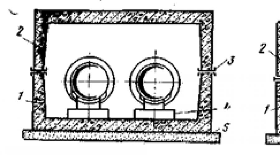
The chamber for installing valves on heating networks is shown in Fig. 148.

Rice. 148. Chamber for installing valves on heating networks:
1 - branch of the supply main pipeline, 2 - branch of the return main pipeline, 3 - chamber, 4 - parallel valves, 5 - pipeline supports, 6 - return main pipeline, 7 - supply main pipeline
When laying heating networks underground, 3 rectangular underground chambers are installed to service shut-off valves. Branches 1 and 2 of the network to consumers are laid in the chambers. Hot water is supplied to the building through a pipeline laid on the right side of the channel. The supply 7 and return 6 pipelines are installed on supports 5 and covered with insulation.
The walls of the chambers are made of bricks, blocks or panels, the ceilings are prefabricated from reinforced concrete in the form of ribbed or flat slabs, the bottom of the chamber is made of concrete. The entrance to the cells is through cast-iron hatches. To descend into the chamber, staples are sealed under the hatches in the wall. The height of the chamber must be at least 1800 mm. The width is chosen so that the passages between the walls and pipes are at least 500 mm.
One of the main features of heat pipelines is the relatively high temperature of the product transported through them - water or steam, in most cases exceeding 100 ° C, which largely determines the nature of the design of heating networks, since it requires thermal insulation and ensuring freedom of movement of pipes when they are heated or cooling.
The presence of thermal insulation and the requirement for free movement of pipes significantly complicates the design of heat pipelines - the latter are laid in channels, tunnels or protective shells.
Periodic heating of the walls of heat pipelines to a temperature of 130-150°C makes anti-corrosion coatings, usually used to protect unheated steel pipelines laid in the ground, unsuitable. To protect heat pipelines from external corrosion, it is necessary to use building insulation structures that prevent the penetration of ground moisture into the pipelines.
The designs of heat pipelines currently used are significantly diverse. Based on the method of installation, heating networks are divided into underground and above-ground (air).
Underground installation of heating network pipelines is carried out:
a) in non-passing and semi-passing channels;
b) in tunnels or sewers together with other communications;
c) in shells of various shapes and in the form of backfill gaskets.
When laying underground, chambers, niches for compensators, fixed supports, etc. are built along the route.
Aboveground installation of heating network pipelines is carried out:
a) on overpasses with a continuous span;
b) on separate masts (supports);
c) on suspended spans (cable-stayed).
A special group of structures includes special structures: underwater, overground and underground passages and a number of others.
The main disadvantages of underground heat pipeline structures used in the construction are: fragility, large heat losses, labor-intensive manufacturing, significant consumption of building materials and high construction costs.
The most widely used structures are prefabricated structures of impassable channels with concrete walls. The use of non-passage channels is justified in the case of laying heating networks in wet soils, provided that associated drainage is installed . You should focus on the use of non-passable channels made from standardized prefabricated reinforced concrete parts. The specified reinforced concrete channels can be used for heating networks with a diameter of up to 600 mm. It is possible to use non-passing channels assembled from vibrating rolling plates.
Non-passing channels with suspended thermal insulation, which forms an air gap around the pipes, are indispensable in sections of the route with self-compensation for thermal elongation of heat pipes. A characteristic feature of ducted heating networks, as opposed to ductless ones, is the provision of movement of heat pipes in the longitudinal and transverse directions.
When laying heat pipelines under passages with heavy traffic and improved road surfaces, semi-through channels made of prefabricated reinforced concrete parts are used. When laying a large number of heat pipes of significant diameters, through-pass tunnels are used.
For heating mains of large diameters, there are also standard channel designs that have proven themselves both in construction and operation. For example, heating mains with a diameter of 700-1200 mm are being built in Moscow. However, channel designs must be improved to achieve more rational solutions. For laying heat pipes, prefabricated reinforced concrete channels of single-cell and double-cell sections are used. Basically, these channels are designed as a semi-through type to allow inspection by maintenance personnel, as well as to ensure maximum reliability of heating mains in operation.
In Moscow and some other cities, ductless laying of heat pipelines with a two-layer cylindrical shell consisting of a reinforced concrete pipe and a heat-insulating layer (mineral wool) has been used.
Reinforced concrete pipes have sufficient mechanical strength, high resistance to shock and vibration loads, and good moisture resistance. Therefore, they reliably protect the heat pipeline from moisture and loads transmitted by the soil. This ensures more favorable conditions for the operation of heat pipelines: the stresses in the pipe walls are reduced and the durability of the thermal insulation is ensured.
The outer reinforced concrete shell remains motionless when the heat pipe moves in the axial direction due to temperature deformations, which distinguishes this structure from a structure with a reinforced foam concrete shell that moves on the ground along with the heat pipe.
A similar design is made using asbestos-cement pipes and reinforced concrete half-cylinders as the outer shell.
The use of ductless structures can be recommended when laying in dry soils with the outer surface of the heat pipes protected by two layers of insulation. Channelless installation of heat pipelines with backfill thermal insulation with peat, diatomaceous earth, etc. turned out to be unsuccessful. Experimental work is currently underway to create backfill material.
The chamber designs used in the construction of heating networks are very diverse. Prefabricated chambers made of reinforced concrete parts are designed for heat pipelines of small and medium diameters. Large chambers are made of concrete blocks and monolithic reinforced concrete. The structures of fixed supports in the channels are made of monolithic and prefabricated reinforced concrete. In Moscow, Novosibirsk and other cities, so-called common collectors have become widespread, in which heat pipes are laid together with electrical and telephone cables, water supply and other underground networks.
Passage channels and common collectors are equipped with electric lighting, telephone communications, ventilation, various automatic control devices and drainage facilities.
In ventilated passage tunnels, a favorable temperature and humidity regime of the air environment is ensured, which contributes to the good preservation of heat pipes.
During the construction of general sewers in Moscow using the open-pit method, the design of large ribbed reinforced concrete blocks, proposed by engineers N. M. Davidyants and A. A. Lyamin, worked well.
The method of jointly laying underground networks in common sewers has a number of advantages, of which the most significant are : increasing the durability of the material part of networks and ensuring the best operating conditions. When operating heating networks in collectors, as well as when it is necessary to build new underground networks, it is not necessary to open up urban areas for repairs. The placement of networks for various purposes in collectors makes it possible to organize their complex and planned design, construction and operation and makes it possible to streamline the entire system of placing underground networks more compactly both in plan and in the cross section of city passages. Underground urban sewers are modern engineering structures.
a - separate;
b - joint;
TK - telephone sewer;
E - electrical cables;
T - heat pipes 2d = 400 mm;
G - gas pipeline d=300 mm
B - water supply d = 300 mm;
C - drain d= 600 mm;
K - sewerage d = 200 mm;
T KAB - telephone cables
Internal view of the common collector

Number of pipelines and cables placed in manifolds of various sections

The design of underground, overground and underwater passages of heat pipelines through natural and artificial obstacles is included in the general complex of designing heating networks and is only in rare cases carried out by specialized organizations.
Underwater crossings of rivers are carried out in the form of passage tunnels and siphons; air crossings across rivers to railway tracks - in the form of bridge crossings. It is also possible to lay heat pipelines along existing bridges and overpasses.
When the route crosses the heating networks of railways and highways, as well as city passages, underground passages are most often constructed, carried out in a closed way to ensure uninterrupted operation of the roads.
Underground passages are made mainly in the form of tunnels, constructed using metal shields of circular cross-section. These tunnels require significant deepening, and therefore often fall into the groundwater zone, which complicates the work and requires the organization of drainage from the tunnel during operation.
Another type of underground passage is the laying of steel cases, inside of which heat pipes are placed. The cases are laid by pressing or puncturing steel pipes with hydraulic jacks. The implementation of this type of transition is advisable where it is possible to pass above the groundwater level without disturbing existing underground communications.
Underpasses made of steel casings are widely used in the construction of heating networks.
The correct choice of one or another type of transition is the main task in the design, since the cost of these structures is very high and significantly increases the total cost of heating networks.
At industrial enterprises, overhead laying of heat pipelines along trestles, often made of rolled metal, has become widespread.
The design of overpasses using precast reinforced concrete is now significantly easier due to the release of the standard project “Unified prefabricated reinforced concrete free-standing supports for process pipelines” (IS-01-06 series).
In urban heating networks, overhead laying of heat pipelines was carried out mainly along metal masts of a lattice structure. Reinforced concrete masts began to be manufactured only at the present time. For example, reinforced concrete masts made from prefabricated parts for heating mains with a diameter of 1200 mm have found application in Moscow. The structural parts of these masts are manufactured at the factory and assembled on the track.