Requirements for the manufacture of double-walled sug containers. General requirements for containers for storing and transporting samples Calculation of frame stationary roofs
Read also
PB 03-576-03 “Rules for the design and safe operation of pressure vessels” OST 26-291-94 “Welded steel vessels and apparatus. General technical conditions".
PB 03-584-03 “Rules for the design, manufacture and acceptance of steel, welded vessels and apparatus.”
Tu 3615-03-76752990-07 and these technical requirements.
1. Subject the internal body of the vessel to a hydraulic test with a test pressure P pr = 2.03 (20.3) MPa (kgf/cm2).
2. Subject the outer body of the vessel to a hydraulic test with a working pressure P pr = 1.6 (16.0) MPa (kgm/cm 2) with simultaneous supply of pressure to the inner body; a pressure difference between the inner and outer body is not allowed.
3. Verify the horizontal position using a level. The level should be set in accordance with the drawing.
4. Coat the outer surface of the vessel with “BODY” primer, gray, in 2 layers, and ML enamel, white. On both sides, apply the inscription “Propane is flammable” using stencils using ML red enamel.
5. Preservation:
- sealing surfaces of flanges and fasteners must be preserved with “Litol-24”, protection option VZ-4, packaging option VU-0, protection period 1 year in conditions 4.
- Clean the inner surface of the case from dirt, degrease, and dry.
6. Depreservation of surfaces coated with “Litol-24” should be carried out with scrapers, followed by wiping with a rag soaked in solvent gasoline.
7. Ground the vessel at the installation site.
8. Sling the device using the sling device at an ambient temperature of at least minus 20 degrees.
9. The surfaces of welds and heat-affected zones subject to non-destructive testing methods (ultrasonic testing, RC, CD) must comply with clause 11.
10. Inspection of welds should be carried out in accordance with the diagram of the location of welds and methods for their inspection ST SND-12-0000000 SRK.
11. Start, stop and test the vessel in winter in accordance with the regulations attached to the operating manual.
12. Technical inspection of the vessel is carried out in accordance with the requirements of the “rules for the design and safe operation of pressure vessels” PB 12-576-03 and the operating manual
13. When operating the vessel, comply with the requirements of PB 12-609-03 “Safety Rules for Facilities Using Liquefied Petroleum Gases.”
14. The vessel is controlled by ROSTEKHNADZOR.
15. Mark the vessel in accordance with OST 26-291-94, which should contain:
- trademark of the manufacturer,
- serial number and order number,
- Year of manufacture,
- technical control marks,
- welder's mark.
Apply the markings with stamps No. 6, 0.2 - 0.3 mm deep and enclose in a frame made of PF-115 enamel, white, GOST 665-76.
16. Apply welders' marks, steel grade, heat number in accordance with the requirements of the drawings.
A properly organized diesel fuel warehouse for a boiler room affects the performance and heat output of the boiler. The storage facility is subject to fire safety requirements. When installing, follow the rules related to the operating features.
Types of fuel tanks for diesel boilers
Tanks for diesel fuel for the boiler room are made of various geometric shapes, from plastic and metal. The containers differ in volume, the capacity ranges from 500 to 10,000 liters.Tanks of a narrow oblong shape are popular, they are optimally suited for installation in boiler rooms with limited free space. Large round tanks, used for ground installation. Thanks to the wide variety of choices, you can choose a container that is suitable in size and can be easily installed in any boiler room.
The main choice of a diesel fuel storage tank is related to the selection of suitable material. Manufacturers produce iron and polymer tanks.
Plastic containers
Plastic containers are in particular demand due to several advantages:- Manufacturing process – molds are made using rotomolding. The advantage of the production method is the absence of technological joining seams, which increases the service life of the container several times. After casting the mold, a drain valve or threaded coupling is cut into the body.
- Installation features - installing plastic fuel tanks for diesel boilers is much easier than in the case of steel analogues. Plastic tolerates temperature changes well, but is inferior to metal in terms of rigidity. The operating temperature of the plastic tank is from -50°C to +50°C.
- Features of operation - polymer tanks are universal, with the help of special fix packages, changing the connection side and other modifications is allowed. The maximum capacity of the tank is 10,000 liters, but, if necessary, upon individual order, a fuel tank (tank) with a volume of 20,000 liters can be manufactured.

When installing a plastic tank, take into account that the material is not able to withstand a large internal load on the walls. Therefore, when installed on the ground, the container is mounted in a special bunker or reinforced with concrete rings.
Metal containers
Fuel tanks for diesel boilers made of metal have limited, mainly industrial, use. The disadvantages include the high cost and weight of the structure, susceptibility to corrosion, and difficulty of maintenance.A metal container installed in the ground requires high-quality insulation of the walls. It is necessary to use a special filtration system that removes small metal particles that enter the fuel during corrosion of the internal walls of the tank.

Which container to choose for a diesel boiler
The selection of a fuel tank is based not only on the material from which the container is made, but also on several performance characteristics. Take into account the required tank volume, manufacturer and cost of the product.As practice shows, it is important to pay attention to the shape of the container: 
To ensure the operation of the system, it is necessary to select a tank of a suitable volume and the appropriate brand of manufacturer.
How to calculate the volume of a diesel fuel storage tank
Capacity calculations are performed depending on the expected consumption of diesel fuel. Calculations are performed as follows:- To obtain 10 kW of heat for an hour, you will need to burn 1 kg of diesel fuel. The resulting thermal energy will be sufficient to heat residential premises with a total area of 100 m².
- During the day, 24 kg of diesel fuel will be burned, during the month - 720 kg, during the heating season - 4320 kg.
- A liter of diesel fuel is equal to 0.84 kg. Accordingly, 4320 kg of diesel fuel will fit in a 5000 liter tank.
The shelf life of fuel does not exceed 6-12 months. The maximum storage volume must accommodate diesel fuel in a volume sufficient to ensure the operation of the boiler for one heating season.
Manufacturers of diesel fuel tanks
Tanks for diesel fuel are universal, suitable for any model of boiler that runs on liquid fuel. A well-made storage unit will last an average of at least 30 years. Products from Korean and domestic manufacturers are popular among buyers - Impulse-Plast, Anion, Ecoprom, Kiturami.There is also demand for the model range of Ukrainian factories. Aquatech products fully comply with European quality standards, but are made taking into account domestic operational realities.
The cost of the tank depends on the manufacturer and material. A plastic container for 1000 liters, Aquatech brand, is offered for 13-15 thousand rubles. A steel tank made by the Kiturami concern, 200 liters, will cost approximately the same price.
Rules for installing a container for diesel boiler equipment
In "Boiler installations", high requirements are placed on the placement of diesel tanks for boiler rooms. Diesel fuel belongs to the class of flammable materials that can cause significant harm to the environment. Requirements relate to placement and connection to the container, maximum storage capacity and other regulations.At the boiler room planning stage, compliance with the following technical conditions is determined:
- Storage location, depending on the type of boiler room and installation method.
- Requirements for containers and fuel supply system.
- Fire regulations.
Where do you place the container with diesel fuel?
SNiP describes in detail all existing options for storing liquid fuel in a boiler room. The main requirement remains to ensure safety and prevent situations that threaten the health and life of service personnel and people in the heated room. The norms stipulate:- The use of liquid fuel boilers for, as well as installation in basements, is prohibited.
- For a separate boiler room, it is allowed to install a ground storage facility located in an attached room. The total volume of fuel should not exceed 150 m³. At the same time, it is allowed to install diesel fuel reserve tanks made of polypropylene directly in the boiler room, provided that the volume does not exceed 5 m³.
- Built-in and attached boiler rooms are connected to closed diesel fuel storage facilities. The warehouse is located in a separate room, not connected to a boiler room or heated building by a common wall.
It is possible to install a sealed supply tank with a maximum volume of up to 800 liters in the boiler room itself. The gap between the burner and the fuel tank is at least 1 m. - According to SNiP, storage of fuel reserves is allowed in underground, semi-underground and above-ground containers made of metal and plastic.

If necessary, with the help of special fix packages, several underground fuel tanks are connected into a single fuel storage facility, the maximum capacity of which is 25,000 liters.
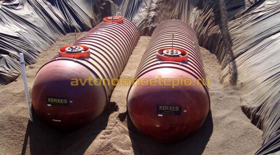
For underground fuel storage with a volume of over 1000 liters, the use of double-walled tanks is required. In the EU, this instruction is mandatory; in Russia, it is in the nature of a recommendation.


Requirements for containers
Durable and sealed containers suitable for operating conditions are used as liquid fuel storage facilities. The material used is enameled or stainless steel, aluminum or plastic.There are several requirements for tanks and their operation:
- Storage facilities are installed in a heated room. For underground installation, well-insulated containers are used. In some cases, additional thermal insulation is required.
- During operation, a large volume of fuel evaporation is generated. A breathing pipeline must be provided in the tank.
- To drain fuel, a special valve is installed.
Fuel supply and filtration system
For ease of operation, a fuel supply and filtration system is provided. The scheme is thought out taking into account the features and characteristics of diesel fuel. The system includes:- Fuel pump - using it, you can pump diesel fuel from the container into the boiler. Modern pumps work in close cooperation with a modulating burner and change the intensity of diesel fuel supply, depending on the thickening. Transportation is carried out through copper fuel hoses connected to the hopper and boiler.
- As storage continues, diesel fuel loses its properties. A heavy precipitate appears. The scheme uses a float fuel intake connecting the diesel boiler to the fuel tank. The module, due to the float, always remains on the surface, which allows you to take clean fuel for work, without sediment.
- At the pipeline supply, a filter for diesel fuel is installed, which cleans diesel fuel from impurities that have entered it as a result of corrosion or due to long-term storage.
- It is possible to supply diesel fuel to the boiler from several containers. To do this, the tanks are connected to each other with fixing packages, practically forming one large container.
- Diesel fuel has one significant drawback. When freezing, diesel fuel thickens, which leads to overconsumption and unnecessary costs. The issue is resolved in several ways.
In some cases, it is practical to heat diesel fuel directly in containers. For greater efficiency, additional heating is carried out already in the chamber of the burner device. - To control the remaining volume of diesel fuel, install a fuel level indicator. In industrial-type storage facilities, an electronic sensor is installed. A mechanical float meter is usually installed in the fuel tank of household appliances.

Fire standards for diesel fuel tanks
Regulatory documents specifying the requirements include SP 89.13330,. Current regulations stipulate compliance with the following measures:- Combining a diesel fuel storage room and a boiler room is prohibited. It is allowed to install a reserve tank indoors (emergency fuel supply), not exceeding 5 m³ or 800 l, depending on the characteristics of the installation.
- The distance from the diesel fuel warehouse to the boiler room is calculated based on the total volume of the tanks and the method of placement.
- The minimum fire-prevention distance between the boiler room and the tank is not less than 9 m. A fuel bunker installed above ground must be separated by an earthen rampart or fire barrier.
- Gaps between the boiler room and the warehouse are calculated in accordance with clause 6.4.48. The permissible distance from the container is affected by the type of storage, above-ground or underground installation, and the fire hazard class of the enterprise or residential building. The construction procedures provide a table according to which all necessary calculations are performed.
- The breathing valve or tank pipeline must fall strictly within the lightning protection zone.
- Heating diesel fuel in fuel tanks using homemade devices is strictly prohibited. For heating, you can only use certified equipment.
An essential requirement for heating containers is grounding of the heating device powered by electricity. Standards regarding the grounding circuit, .
GOST R 53210-2008
Group D08
NATIONAL STANDARD OF THE RUSSIAN FEDERATION
COMBINED CONTAINERS
General technical conditions
Composite containers. General specifications
OKS 55.020
OKP 31 7700
Date of introduction 2010-01-01
Preface
The goals and principles of standardization in the Russian Federation are established by Federal Law of December 27, 2002 N 184-FZ "On Technical Regulation", and the rules for applying national standards of the Russian Federation are GOST R 1.0-2004 "Standardization in the Russian Federation. Basic Provisions"
Standard information
1 DEVELOPED AND INTRODUCED by the Technical Committee for Standardization TC 273 "Composite materials and products made from them"
2 APPROVED AND ENTERED INTO EFFECT by Order of the Federal Agency for Technical Regulation and Metrology dated December 25, 2008 N 699-st
3 INTRODUCED FOR THE FIRST TIME
Information about changes to this standard is published in the annually published information index "National Standards", and the text of changes and amendments is published in the monthly published information index "National Standards". In case of revision (replacement) or cancellation of this standard, the corresponding notice will be published in the monthly published information index "National Standards". Relevant information, notifications and texts are also posted in the public information system - on the official website of the Federal Agency for Technical Regulation and Metrology on the Internet
1 area of use
1 area of use
This standard applies to containers with a capacity of 0.45 to 1.5 m, having a combined (composite) design, intended for storage and transportation by rail, water and road transport (in direct and mixed communications) of bulk and liquid cargo loaded under pressure or by gravity (hereinafter referred to as containers).
The standard does not apply to soft containers.
2 Normative references
This standard uses normative references to the following standards:
GOST R 1.12-2004 Standardization in the Russian Federation. Terms and Definitions
GOST R 50460-92 Mark of conformity for mandatory certification. Shape, dimensions and technical requirements
GOST R 50798-95 Distinguishing sign for vehicles participating in international road traffic. Types and sizes. Technical requirements
GOST R 51760-2001 Polymer consumer containers. General technical conditions
GOST R 51827-2001 Containers. Test methods for leak tightness and hydraulic pressure
GOST R 52202-2004 (ISO 830-99) Freight containers. Terms and Definitions
GOST 2.601-2006 Unified system of design documentation. Operational documents
GOST 9.303-84 Unified system of protection against corrosion and aging. Metallic and non-metallic inorganic coatings. General requirements for selection
GOST 12.0.001-82 System of occupational safety standards. Basic provisions
GOST 12.1.004-91 System of occupational safety standards. General requirements
GOST 9330-76 Basic connections of parts made of wood and wood materials. Types and sizes
GOST 14192-96 Marking of cargo
GOST 16504-81 System of state testing of products. Testing and quality control of products. Basic terms and definitions
GOST 17527-2003 Packaging. Terms and Definitions
GOST 19433-88 Dangerous goods. Classification and labeling
GOST 21140-88 Containers. Sizing system
GOST 26319-84 Dangerous goods. Package
Note - When using this standard, it is advisable to check the validity of the reference standards in the public information system - on the official website of the Federal Agency for Technical Regulation and Metrology on the Internet or according to the annually published information index "National Standards", which was published as of January 1 of the current year and according to the corresponding monthly information indexes published in the current year. If the reference standard is replaced (changed), then when using this standard you should be guided by the replacing (changed) standard. If the reference standard is canceled without replacement, then the provision in which a reference is made to it is applied in the part that does not affect this reference.
3 Terms and definitions
This standard uses terms according to GOST R 1.12, GOST 16504, GOST R 52076 *, GOST R 52202 and GOST 17527, as well as the following terms with corresponding definitions:
________________
* GOST 31314.3-2006 is in force on the territory of the Russian Federation. - Database manufacturer's note.
3.1 combination container: A rigid structure consisting of a container, equipped with or without operating devices, enclosed in a supporting frame.
3.2 frame: A collapsible design that protects the container from the effects of static and dynamic loads that occur during lifting, loading, stacking, securing and transporting the container.
3.3 capacity: The internal volume of a container (container), determined by its internal dimensions without taking into account the filling of necks and cavities of operating devices.
4 Classification, main parameters and dimensions
4.1 Containers are manufactured with a capacity of 0.45 to 1.5 m.
4.2 Types of containers, their symbols, depending on the materials used to manufacture the container and frame, are given in Table 1.
Table 1
Container type designation | Material designation | Purpose |
For liquids and viscous loads |
||
B - aluminum | For bulk cargo loaded and (or) unloaded by gravity |
|
For bulk cargo loaded and (or) unloaded under pressure more than 10 kPa |
||
For liquids and viscous loads |
||
N - other metals (except steel and aluminum) | For bulk cargo loaded and (or) unloaded by gravity |
|
For bulk cargo loaded and (or) unloaded under pressure more than 10 kPa |
||
For liquids and viscous loads |
||
N - polymer materials | For bulk cargo loaded and (or) unloaded by gravity |
|
For bulk cargo loaded and (or) unloaded under pressure more than 10 kPa |
||
For liquids and viscous loads |
||
C - natural wood of various species | ||
D - plywood | For bulk cargo loaded and (or) unloaded by gravity |
|
F - wood-fiber or wood-shaving material | For bulk cargo loaded and (or) unloaded by gravity, with an internal liner |
|
Notes 1 The letter Z in the container type designation indicates the type of material used to make the frame. 2 The numbers indicate the types of containers: 11 - containers intended for bulk cargo loaded and (or) unloaded by gravity; 21 - containers intended for bulk cargo loaded and (or) unloaded under pressure of more than 10 kPa; 31 - containers for liquid and viscous cargo. |
||
4.3 The carrying capacity of containers, maximum net weight, maximum gross weight are established in the technical documentation for containers for specific types of products.
4.4 The symbol of the container includes:
- name of the container;
- container type designation;
- nominal outer dimensions of the container, m;
- maximum permissible load when stacking, kg;
- load capacity, kg;
- designation of this standard or technical documentation for containers for a specific type of product (if available).
An example of a symbol for a combined container (steel frame and container made of polymer material) for bulk cargo unloaded by gravity; nominal external dimensions 1.0x1.0x1.0 m, load capacity 1500 kg, with maximum permissible stacking load 5500 kg:
Combined container 11 NA 1.0x1.0x1.0/1500/5500 - GOST R 53210-2008
5 General technical requirements
5.1 Containers are manufactured in accordance with the requirements of this standard for technical documentation for containers for specific types of products.
It is allowed, in agreement with the customer, to produce containers based on standard samples.
5.2 Design requirements
5.2.1 The design of the container must ensure the safety of cargo under given operating conditions and ease of maintenance and repair.
5.2.2 It is not allowed to use containers without a frame. Loading and unloading of polymer containers is carried out without removing them from the frame.
5.2.3 The supporting surface of containers for which stacking is intended must ensure the stability of the stack.
5.2.4 Structural elements of the container frame should not damage polymer containers during operation.
5.2.5 The container frame may have a fixed or removable pallet, which is used for mechanized loading and/or unloading of the container.
“Pockets” for forks are not allowed on polymer containers.
5.2.6 Containers intended for transporting cargo under pressure must be equipped with safety devices.
Safety devices must be fully open at a pressure not exceeding the test pressure to prevent excessive internal pressure from occurring.
5.2.7 Any container closure device which, if not closed, could lead to a hazardous situation must be capable of being manually operated and indicating its operating position.
5.2.8 The design of containers must provide for the possibility of sealing them.
5.2.9 Containers must maintain operational characteristics after staying for two hours at a temperature not lower than plus (60±2) °C and/or not higher than minus (50±2) °C.
5.2.10 The dimensions of containers, taking into account the requirements of GOST 21140, are established in the technical documentation for containers for specific types of products.
5.2.11 Coatings are selected in accordance with the requirements of GOST 9.303 depending on the type of material from which the containers are made.
5.3 Requirements for liner containers
5.3.1 Designed openings of containers (except for those equipped with safety devices to relieve excess pressure) must have locking devices to prevent loss of cargo.
5.3.2 Openings of containers located below the top level of the packaged cargo must have manually operated shut-off devices, as well as, in order to avoid accidental leaks, additional closing elements on the outside of the shut-off device (plugs, blind flanges with bolts, etc.).
5.3.3 The wall thickness of the container is established based on the specific purpose of the container and compliance with the requirements for structural strength specified in this standard.
For metal containers, the wall thickness is set to at least 1.5 mm.
5.3.4 Metal containers intended for liquids must have a welded structure.
5.3.5 For containers made of aluminum alloys, it is not allowed to use removable parts (lids, closures, etc.) made of steel without a protective corrosion-resistant coating (to avoid contact corrosion).
5.3.6 Containers assembled with operational devices and closed necks must be sealed.
5.3.7 Tanks intended for cargo loaded (unloaded) under pressure must withstand hydraulic pressure tests.
Test pressure is established in the technical documentation for containers for specific types of products ranging from:
- the value obtained by multiplying the coefficient 1.75 by the vapor pressure at a temperature of the transported substance of 50 °C minus 100 kPa;
- the value obtained by multiplying the coefficient 1.5 by the vapor pressure at the temperature of the transported substance 55 °C minus 100 kPa to 500 kPa.
5.3.8 Regardless of the calculation results, the test pressure must be no less than:
- 250 kPa - for containers of types 21AZ, 21BZ, 21NZ, 31AZ, 31BZ;
- 100 kPa - for containers of types 21AZ, 21BZ, 21NZ, 31NZ;
- 75 kPa - for containers of types 21HZ, 31HZ;
- 250 kPa - for containers used for the transportation of dangerous goods of packing group I;
- 100 kPa - for containers used for transporting goods of packing groups II and III.
5.4 Requirements for the container frame
5.4.1 The design of the container must ensure that there are no concentrated loads in any part of the container.
5.4.2 When using a removable pallet, the supporting frame must be securely fastened to the pallet with fasteners.
5.4.3 The design of the frame must ensure its assembly and disassembly within the limits necessary to ensure maintenance of the tank.
5.4.4 Types and methods of connecting individual components of the frame are indicated in the technical documentation for containers for specific types of products, taking into account the conditions in 5.4.1.
5.4.5 The frame design must include structural elements for lifting the container during loading and unloading operations.
It is not allowed to lift wooden frames by the top or install structural elements to lift them by the top.
5.5 Requirements for container operating devices
5.5.1 The design of containers must include locking, safety or other operational devices that ensure safe operation of the containers.
5.5.2 Operating devices are positioned and secured in such a way that they cannot be damaged during operation.
Operating devices can be protected by covers or casings.
5.5.3 Locking devices must be protected from accidental opening, and their “open” or “closed” positions must be fixed and easily distinguishable.
5.5.4 For containers used for the transportation and storage of liquid cargo, additional sealing of the discharge opening with a screw cap or similar device must be provided.
5.5.5 Safety devices under normal container operating conditions must have a minimum air throughput of at least 0.05 m/s (at an absolute pressure of 100 kPa and a temperature of 15 °C).
5.5.6 Operating devices of containers, incl. necks, discharge and locking devices must have inscriptions indicating their purpose.
Each safety device must clearly indicate the pressure to which it is set.
5.5.7 Containers intended to transport liquids shall have a device to release sufficient steam to prevent rupture of the container.
The response pressure shall not exceed 65 kPa and shall not be less than the test pressure specified in 5.3.7 and 5.3.8.
5.6 Requirements for the mechanical strength of containers
5.6.1 Containers must withstand the internal pressure of cargo loaded to the maximum permissible gross weight, as well as the loads arising under specified loading and unloading conditions.
5.6.2 Containers must withstand the influence of inertial forces of the cargo they contain, which arise during transportation as a result of vehicle movement.
The effects of inertia forces in the longitudinal, transverse and vertical directions should be taken equal to 2·, where is the maximum permissible gross mass of the container, kg; - constant value of free fall acceleration equal to 9.8 m/s.
These loads are taken into account as uniformly distributed, acting through the geometric center of the container and not increasing the pressure in the vapor space of the container.
5.6.3 Containers must withstand free fall impact tests without destruction or leakage.
5.6.4 Containers must withstand the loads arising during loading and unloading operations (when lifted by the upper and/or lower part).
5.6.5 Containers must withstand the loads that occur during stacking, which are established in the technical documentation for containers for specific types of products.
5.7 Material requirements
5.7.1 Requirements for materials used for the manufacture of containers are established in the technical documentation for containers for specific types of products, taking into account the following requirements.
5.7.2 Metal containers are made from materials that meet the following requirements:
- for steel and its alloys: elongation at break in percentage should not exceed (but not less than 20%);
- for aluminum alloys: elongation at break in percentage should not exceed (but not less than 8%),
where is the guaranteed minimum tensile strength of the metal used, N/mm.
In the case of austenitic steels, the specified minimum value can be increased by 15%.
5.7.3 Samples used to determine elongation at break must be taken transversely to the rolled product in such a way that
where is the length of the metal sample before testing, mm;
- diameter, mm;
- cross-sectional area of the test sample, mm.
5.7.4 Polymer materials used for the manufacture of containers must be resistant to aging and destruction under the influence of packaged products and ultraviolet radiation.
5.7.5 For the manufacture of polymer containers, used polymer materials should not be used, with the exception of waste obtained during the production process.
5.7.6 Wood used in the manufacture of containers must be dry. Wood moisture content, depending on the purpose of the container, is indicated in the technical documentation for containers for specific types of products. The wood should not have defects that reduce the strength characteristics of the container.
Container structural parts must be made of solid wood or wood slab, assembled with joints of types K-1 - K-6 according to GOST 9330 with glue or using corrugated metal plates (clips).
5.7.7 Plywood used for the manufacture of container containers must be waterproof three-layer made from peeled, planed or sawn veneer. Plywood defects that reduce the strength of the container are not allowed.
For the manufacture of container containers, it is allowed to use other materials with strength not lower than those specified.
5.7.8 When making containers from wood materials, waterproof solid wood fiber or particle boards or other similar wood materials are used.
5.7.9 Materials used for the manufacture of container containers must be chemically resistant to the effects of the cargo being packaged or have an inert coating or lining (liner) made of polymer film or moisture-resistant paper (waxed, bitumenized or laminated with polyethylene).
5.7.10 Materials and products used for the manufacture of containers in contact with food, medicines or cosmetics must be approved for use by the sanitary and epidemiological supervision authorities of the Russian Federation.
5.7.11 The resistance of polymer materials to ultraviolet radiation must be ensured by the addition of carbon black, pigments or inhibitors.
The additives used must be compatible with the goods packed in the containers.
5.8 Completeness
5.8.1 Containers are supplied in sets.
5.8.2 The kit, as agreed with the customer, includes special connecting elements or pipes required when filling containers.
5.8.3 The kit must include operational documents in accordance with GOST 2.601.
5.9 Marking
5.9.1 A label made of corrosion-resistant material with data allowing identification of the container is attached to each container.
5.9.2 Methods of marking: branding; embossing; etching; percussion or other methods. Marking with paint is not permitted.
5.9.3 Marking must contain:
- name of the manufacturer and (or) its trademark;
- the inscription “Made in Russia” or the country code “RUS”, or the distinctive sign of vehicles participating in international road traffic in accordance with GOST R 50798 (for containers used in international transport);
- container owner code, consisting of three capital letters, registered with the International Container Bureau or through a domestic registration organization;
- symbol of the container in accordance with this standard;
- symbol of the packaging group of dangerous goods ("X" - for containers of packing groups I, II and III, only for bulk cargo; "Y" - for containers of groups II and III; "Z" - for containers of packing group III) according to GOST 26319 for containers intended for the transportation of dangerous goods;
- month and year of manufacture;
- UN graphic symbol for transport packaging.
For restored containers, the marking must contain:
- the name of the restorer (abbreviated or coded), if the restoration was carried out by an enterprise that was not the manufacturer of the container;
- year of restoration;
- the letter “R” if the container has been restored;
- the letter “L” if the container was subjected to a leak test.
The need to apply additional markings according to Table 2 is stipulated in the technical documentation for containers for specific types of products.
Notes
1 If the marking is stamped or embossed, instead of the UN graphic symbol for transport containers, the designation “UN” may be used.
2 Containers made of polymer materials are marked with environmental labeling and information about the possibility of recycling.
table 2
Additional markings | Type of container materials |
||
metal | polymer | wood and wood |
|
Capacity at 20 °C, m | |||
Maximum permissible gross weight, kg | |||
Test (gauge) pressure, kPa, accurate to 10 kPa | |||
Maximum filling (emptying) pressure, kPa, accurate to 10 kPa | |||
Container serial number | |||
Case material and its minimum thickness, mm | |||
Date of last leak test (month, year) | |||
Date of last check (month and year) | |||
Notes 1 Indication of the unit of measurement of capacity and gross weight is mandatory. 2 The “+” sign means mandatory data reduction. |
|||
5.9.4 Depending on the cargo being packed, handling marks and inscriptions in accordance with GOST 14192 and GOST 19433 may be applied to the container in accordance with the technical documentation for containers for specific types of products.
5.10 Packaging
Containers are supplied without packaging.
Shipping documentation, as well as operational documents in accordance with 5.8.3, are packaged in a plastic film bag.
Removable and spare components of containers are packaged in individual containers, securely attached to the container frame in the place indicated in the drawings for the container for a specific type of product.
6 Safety and environmental requirements
6.1 When manufacturing containers, the safety rules in accordance with GOST 12.0.001, fire safety rules in accordance with GOST 12.1.004, as well as standard safety rules for industrial enterprises are observed.
6.2 During the manufacturing process of containers, the possibility of environmental pollution by production waste must be excluded.
Waste that is not suitable for recycling, as well as containers that are not suitable for further use, must be disposed of.
7 Acceptance rules
7.1 Containers are accepted individually or in batches.
To control the quality of container containers, tests are carried out according to Table 3.
Table 3
Container capacity | Type of test |
||||||||
Chemical resistance test | Control of dimensions, appearance, capacity, wall thickness | Base lifting test* | Lifting test from the top* | Stacking strength test** | Leak test | Hydraulic pressure test | Free fall impact test | Heating and cooling test |
|
Metal: | |||||||||
11NZ, 21AZ, 21BZ, 21NZ, 31AZ, 31BZ, 31NZ | |||||||||
Polymer: | |||||||||
Made from wood and wood materials | |||||||||
* If the container design allows for this loading/unloading method. ** If the container design allows for stacking. *** For free fall testing, use the same type of container. Note - The sign “+” means tests are carried out, “-” means they are not carried out. |
|||||||||
7.2 The markings, completeness and dimensions are checked for each container.
Each container intended for packaging liquids is subjected to a leak test.
This test is carried out after manufacturing or restoration of the container, and then every 2.5 years.
Tests of other parameters are carried out on samples of containers of each type.
7.3 The number of samples and the order of sampling are determined in the technical documentation for specific types of containers.
7.4 Labels are attached to containers selected for testing indicating:
- symbol of the container in accordance with the requirements of this standard;
- name of the manufacturer;
- batch number;
- batch volume;
- date of manufacture (month, year);
- date of sample collection;
- sampling locations;
- number of samples;
- surname and initials of the person who carried out the sampling.
8 Test methods
8.1 Test requirements
8.1.1 To conduct free-fall impact and stacking strength tests, containers are filled with the cargo they are intended to transport.
It is allowed to fill containers with a dimensional-mass equivalent that has physical properties similar to the properties of the packaged cargo, if this does not affect the reliability of the test results.
It is allowed to use additives (steel, cast iron shot or similar) to achieve the required net weight of the load, if this does not affect the reliability of the test results.
8.1.2 If a different (substitute) load is used to fill the container during the free fall impact test, it must have the same density and viscosity as the load the container is intended to transport.
It is allowed to fill containers with water or water with antifreeze.
8.1.3 It is allowed to conduct random tests for those containers that, in comparison with already tested containers of the same type, have insignificant differences (for example, slightly smaller nominal dimensions).
8.1.4 For the free fall impact test and stacking, containers intended for liquid cargo are filled with liquid to 98%, for bulk cargo - with bulk cargo to 95% of capacity.
8.1.5 The temperature of containers made of polymeric materials and the cargo contained in them during the free fall impact test is reduced to minus 18 °C, unless otherwise indicated in the technical documentation for containers for specific cargo.
8.1.6 When testing chemical resistance, only containers can be used.
It is allowed to use samples of containers of smaller overall dimensions for testing for chemical resistance, made of the same material and using the same technology as the container being tested.
8.1.7 The time and parameters of conditioning before testing samples of containers made of polymer materials are established in the technical documentation for containers for specific types of products.
8.2 Chemical resistance tests
8.2.1 To control the chemical resistance of the materials from which the containers are made to the effects of the packaged cargo, samples of containers are filled with the packaged cargo and kept.
This test is carried out when testing the design of containers.
8.2.2 The chemical resistance of polymer containers is controlled according to GOST R 51760.
The change in the dimensions of samples made of polymeric materials should not exceed ±3% within 28 days and ±5% within 6 months.
The weight loss of the cargo should not exceed 0.5% for 28 days at a temperature of (20±2) °C and 3% at the same temperature for 6 months.
8.2.3 It is allowed to establish other requirements and test parameters in the technical documentation for containers for specific types of products, depending on the material of the container and the type of cargo being packaged.
8.3 Control of appearance, build quality, markings, completeness
8.3.1 The appearance, markings and completeness of containers are checked visually without the use of magnifying devices, by comparison with working drawings and control reference samples (if available), approved in the prescribed manner.
8.4 Control of geometric dimensions and wall thickness
To check the dimensions and wall thickness, the container is placed in the operating position on a flat horizontal surface.
Control is carried out using methods and using measuring instruments provided for in the technical documentation for containers for specific types of products.
8.5 Capacity and load control
8.5.1 When determining the capacity, the container is filled with water up to the beginning of the neck, pouring water at a temperature of (20±5) °C from a measuring container.
Operating devices must be removed and their connection points hermetically sealed.
8.5.2 The maximum permissible gross weight of a container is determined by multiplying the total capacity by the highest cargo density provided for packaging, followed by adding the weight of the empty container.
The maximum load capacity of the tested container is determined by the formula
where is the maximum permissible gross weight of the container, kg;
- weight of the empty container, kg.
8.5.3 To determine the total capacity, the container assembled with operating devices is filled with water according to 8.5.1 until the water overflows through the neck.
8.6 Base lift tests
8.6.1 Test performance
Tests are carried out for all containers whose design allows for lifting by the base.
The tests are carried out to check the container's ability to withstand the loads that arise when it is lifted using lifting devices.
8.6.2 Preparing the container for testing
The container must be loaded so that its gross weight is 1.25 times the maximum permissible gross weight, and the load must be evenly distributed.
8.6.3 Test performance
The container is lifted and lowered twice by a loader with the fork inserted in the center at 3/4 of the width of the base (if the fork insertion points are not defined).
The fork should be inserted in the direction the fork is inserted. If there are several directions of input, then the gripper is inserted from all directions.
8.6.4 After testing there should be no loss of contents, residual deformations or malfunctions leading to the unsuitability of the container for further use.
8.7 Top lift tests
8.7.1 Test conditions
Tests are carried out for all containers whose frame design allows lifting from the top.
The tests are carried out to verify the ability of containers to withstand loads arising when lifting forces are applied vertically, as well as the ability of containers to withstand loads arising when lifting forces are applied at an angle of 45° to the vertical.
These tests are also used to monitor the ability of containers to withstand loads resulting from acceleration forces during lifting.
8.7.2 Preparation for testing
Containers are loaded so that their gross weight is twice the maximum permissible gross weight. The load must be distributed evenly.
The container is lifted in such a way that no acceleration or deceleration occurs.
8.7.3 Test performance
Containers are lifted:
- using a pair of lifting devices located diagonally so that the lifting force acts vertically, and hold in this position for 5 minutes;
- using a pair of diagonally positioned lifting devices so that the forces applied through the slings act at an angle of 45° to the vertical towards the center, and hold the container in this position for 5 minutes.
8.7.4 After completion of the tests, the following are not allowed: loss of contents, residual deformations or malfunctions leading to the unsuitability of the container for further use.
8.8 Stacking strength tests
8.8.1 Test conditions
Tests are carried out for all containers whose design allows for stacking during operation.
8.8.2 Preparation and inspection
The container must be filled to its maximum permissible gross weight.
8.8.3 Test performance
8.8.3.1 The container is placed on a horizontal rigid surface and subjected to a uniformly distributed load for at least:
- 5 min - for containers with a metal frame;
- 28 days at plus 40 °C - for containers with a polymer frame;
- 24 hours - for other containers.
8.8.3.2 The load used is:
- one or more containers of the same type, which are loaded to the maximum permissible gross weight;
- uniformly distributed loads of appropriate mass are placed on a flat plate or stand simulating the base of the container, installed on the test container.
8.8.4 Calculation of test load
The weight of the cargo installed on the container must be at least 1.8 times greater than the maximum permissible design load when stacking.
8.8.5 After testing, the following are not allowed: loss of contents, residual deformations or malfunctions leading to the unsuitability of the container for further use.
8.9 Leak tests
8.9.1 Tests are carried out in accordance with GOST R 51827 with the following additions:
- tests are carried out for containers (complete with all operational devices) intended for transporting liquids or bulk cargo loaded or unloaded under pressure;
- tests are carried out for at least 10 minutes with compressed air at a constant gauge pressure of at least 20 kPa (or at a pressure not lower than 0.25 of the permissible operating pressure);
- all openings provided in operational devices must be plugged;
- during testing, there should be no air leakage in the connections of operational devices, welds of containers and other parts of containers.
8.9.2 After completion of the tests, the following are not allowed: loss of contents, residual deformations or malfunctions leading to the unsuitability of the container for further use.
8.10 Hydraulic pressure tests
8.10.1 Tests are carried out in accordance with GOST R 51827 with the following additions:
- tests are carried out on containers (complete with all operational devices) intended for transporting liquids or bulk cargo loaded or unloaded under pressure;
- three samples of containers are tested;
- tests are carried out for at least 10 minutes with the application of a test pressure not lower than that established in 5.3.7 and 5.3.8 of this standard.
8.11 Free fall impact tests
8.11.1 Test method
Containers are dropped onto a hard, flat, horizontal impact platform so that the point of impact is at that part of the base of the container that is considered the most vulnerable.
Each drop can use the same or different containers.
8.11.2 The drop height during impact testing during free fall of containers intended for bulk, viscous cargo or liquids with a density of no more than 1.2 g/cm, as well as when replacing liquids with water, must be at least 0.8 m.
The drop height during the free fall impact test of containers intended for liquids with a density of more than 1.2 g/cm when replacing the packaged liquid with water (or water with added antifreeze) must be at least 0.67 m.
8.11.3 During testing, loss of contents from the container is not allowed.
After completion of the tests, the following are not allowed: loss of contents, residual deformations or malfunctions leading to the unsuitability of the container for further use.
8.12 Heating and cooling tests
The tests are carried out before the free fall impact tests.
Samples of containers are placed in a climatic chamber, the temperature is set sequentially plus (60±2) °C and minus (50±2) °C, depending on the type of test. The samples are kept in the chamber for two hours at each temperature.
The samples are then removed from the chamber and kept at room temperature for 30 minutes, then the samples are inspected and the dimensions are checked.
9 Rules for recording inspection results
The control results are recorded in a journal or documented in a protocol containing:
- name and address of the organization that conducted the tests;
- name and address of the applicant organization;
- individual test report number;
- name of the container manufacturer;
- symbol of the container according to this standard;
- description of the container design (purpose, operational devices, etc.), including the name of the container material and method of its manufacture (for example, molding, blowing, etc.), as well as working drawings and/or photographs;
- batch number and volume;
- date of manufacture of the container;
- date of receipt of containers for testing;
- date of drawing up the test report;
- signatures of the persons conducting the tests;
- conditioning conditions for samples (during conditioning);
- test conditions;
- characteristics of the load used during testing (viscosity, density - for liquids, particle sizes - for bulk substances);
- types of test benches and numbers of test bench certification acts;
- types, brands and date of verification of control equipment;
- number of samples tested;
- capacity, m;
- test methods used;
- any deviations from these test methods;
- recording of test results with all explanations and comments;
- designation of this standard;
- number and date of the sanitary and epidemiological certificate for containers intended for transportation and storage of food products, medicines and cosmetics.
10 Transportation and storage
10.1 Containers are transported in accordance with the rules for the carriage of goods in force for specific types of transport.
11 Operating instructions
11.1 The conditions and methods of operating containers must comply with those specified in the operational documentation (taking into account their specific purpose, the type of cargo being packed and transportation conditions).
11.2 Organizations using containers must fully comply with the requirements for their filling, washing, loading and unloading, transportation and storage.
11.3 Attaching foreign parts and technological equipment to containers is not permitted.
11.4 It is not permitted to sequentially fill containers with different types of products without first washing the containers.
12 Manufacturer's warranty
12.1 The manufacturer must ensure that containers comply with the requirements of this standard, subject to compliance with the rules of operation, transportation and storage.
12.2 Warranty periods for storage and operation of containers are established in the technical documentation for containers for specific types of products.
Electronic document text
prepared by Kodeks JSC and verified against:
official publication
M.: Standartinform, 2010
Section Contents
In boiler rooms, closed tanks with a steam cushion should be provided to collect drainage from steam lines, condensate from steam-water heaters and heaters of the heating and ventilation system of the boiler room. When condensate collection tanks are located in or near the boiler room, all drainage should be directed to these tanks. At the same time, special drainage collection tanks are not provided in the boiler room [1].
In boiler rooms for open heating systems and in boiler rooms with installations for centralized hot water supply, as a rule, hot water storage tanks should be provided.
The selection of storage tanks is made in accordance with building codes and rules for the design of heating networks.
During the feasibility study, storage tanks may not be included.
As part of water treatment plants for the reuse of wash water after clarification filters, it is necessary to provide a tank and pumps for uniform supply of this water along with the sediment throughout the day to the lower part of the clarifier. The tank capacity must be designed to receive water from two washes.
To collect water after clarifiers, it is necessary to provide tanks with a capacity equal to the total capacity of the clarifiers. When using the indicated tanks and for washing clarification filters, the capacity of the tanks should be taken equal to the sum of the hourly productivity of the clarifiers and the water consumption for washing the two clarification filters.
Loosening of filter materials must be provided with rinsing water with the installation of a tank for each group of filters for different purposes. If it is impossible to place the tank at a height that ensures loosening, a pump should be installed. The useful capacity of the tank should be determined based on the amount of water required for one loosening wash.
The volume of the strong acid measuring tank should be determined from the condition of regeneration of one filter. The volume of supply tanks for the flocculant should be determined based on the shelf life of the solution stock of no more than 20 days.
The number of tanks for lime milk should be at least two. The concentration of lime milk in supply tanks must be no more than 5% of CaO.
The height of tanks for coagulant, table salt, soda ash and phosphates should be no more than 2 m, for lime - no more than 1.5 m. When loading and unloading reagents with mechanization, the height of the tanks can be increased: coagulant, table salt, soda ash and phosphates - up to 3.5 m, lime - up to 2.5 m. Deepening of tanks by more than 2.5 m is not allowed.
As a rule, “wet” storage warehouses should be provided for reagents. When reagent consumption is up to 3 tons per month, they can be stored dry in closed warehouses.
The flocculant must be stored in containers and at a temperature not lower than 5° C. The shelf life should be no more than 6 months.
The capacity of reagent storage warehouses should be taken upon delivery: by road transport - based on 10-day consumption; by rail - monthly consumption; through pipelines - daily flow. When delivering reagents by rail, it is necessary to provide for the possibility of receiving one wagon or tank; at the same time, at the time of unloading at the warehouse, a 10-day supply of reagents must be taken into account. The supply of reagents is determined based on the maximum daily consumption.
When designing reagent warehouses, one should take into account the possibility of their cooperation with the central warehouses of enterprises or regional operation services.
The capacity of tanks for “wet” storage of reagents should be taken at the rate of 1.5 m 3 per 1 ton of dry reagent. In tanks for “wet” storage of coagulant, it is necessary to provide a device for mixing the solution. When locating tanks for “wet” storage of reagents outside the building, devices must be provided to protect solutions from freezing.
Bunkers for solid fuel should be designed with a smooth internal surface and a shape that allows fuel to drain by gravity. The angle of inclination of the walls of receiving and transfer bunkers for coal should be at least 55°, for peat and smearable coal - at least 60°.
The angle of inclination of the walls of boiler bunkers and the conical part of silos , as well as overflow hoses and chutes for coal should be taken at least 60°, and for peat - at least 65°. The inside edges of bin corners should be rounded or chamfered. Coal and peat bunkers should be equipped with devices to prevent fuel from getting stuck.
The capacity of the bunkers (for each boiler) must provide the following fuel reserves according to the rated load of the boiler [7]:
- for hard coals and AS……………………….. 8 hours;
- for brown coals................................................... 5 hours;
- for frestorf..................................................................... 3 hours.
Receiving tank capacity for liquid fuel delivered by rail, must ensure that in case of an emergency stop of the transfer pumps, fuel is received within 30 minutes. The tank capacity is calculated based on the standard drainage time in the summer.
To pump fuel from the receiving tank to the fuel storage facility, at least two pumps (both working) must be provided. The pump capacity is selected based on the amount of fuel drained into one unit and the standard drain time.
For fuel oil storage, reinforced concrete tanks (underground and above-ground with coating) should be provided. The use of steel tanks for storing fuel oil is permitted only with the permission of the State Construction Committee of the Russian Federation. Steel tanks should be provided for storing light fuel oil and liquid additives.
For above-ground metal tanks installed in areas with an average outdoor temperature of up to 9 ° C, thermal insulation made of non-combustible materials must be provided.
Table 10.4 Liquid fuel storage capacity depending on daily consumption should be taken according to table. 10.4.
Table 10.4. Standards for determining the size of liquid fuel storage capacity
| Name and method of fuel delivery | Liquid fuel storage capacity |
| 1. Main and reserve, delivered by rail | For 10-day consumption |
| 2. The same, delivered by road transport | For 5-day consumption |
| 3. Emergency for gas-fired boiler houses, delivered by rail or road | For 3-day consumption |
| 4. Main, backup and emergency, delivered through pipelines | For 2-day consumption |
| 5. Kindling for boiler houses with a capacity of 100 Gcal/h and less | Two tanks of 100 t each |
| 6. The same for boiler houses with a capacity of more than 100 Gcal/h | Two tanks of 200 t each |
| Note. Reserve is a liquid fuel intended for combustion over a long period along with gas during interruptions in its supply. | |
At least two tanks must be provided for storing main and reserve fuel. One tank may be installed to store emergency fuel.
The total capacity of tanks for storing liquid additives is determined by the conditions of their delivery (the capacity of railway or road tanks), but must be at least 0.5 of the capacity of the fuel oil storage facility. The number of tanks is accepted to be at least two.
For built-in and attached individual liquid fuel boiler houses, a fuel storage facility should be provided, located outside the boiler room and heated buildings, with a capacity calculated based on storage conditions of at least five-day fuel consumption determined for the mode corresponding to the heat load of the boiler room in the coldest month. The number of tanks is not limited.
The heating temperature of liquid fuel in railway tanks should be 40 - 30° C for fuel oil, 100 - 60° C for fuel oil, 10° C for light oil fuel . Heating of fuel delivered in automobile tanks is not provided. In receiving containers, trays and pipes through which fuel oil is drained, devices should be provided to maintain the specified temperatures. In places where liquid fuel is taken from fuel storage tanks, the temperature of fuel oil grade 40 must be maintained at least 60 ° C, fuel oil grade 100 must be at least 80 ° C, light oil fuel must be at least 10 ° WITH .
To heat fuel in railway tanks, steam at a pressure of 6-10 kgf/cm 2 should be used. To heat fuel oil in heaters, fuel storage tanks, receiving tanks and drain trays, steam with a pressure of 6-10 kgf/cm2 or high-temperature water with a temperature of at least 120 C can be used.
For liquid fuel in built-in and attached boiler houses, if it is necessary to heat it in external containers, the coolant of the same boiler houses is used.
To maintain the temperature of fuel oil in fuel storage tanks, a circulation heating system should be used. When circulating heating of fuel oil, an independent scheme can be used, which provides for the installation of special pumps and heaters, or heaters and pumps for supplying fuel oil to the boiler room can be used.
The choice of the method of circulation heating of fuel oil is made based on a comparison of the technical and economic indicators of the options.
Coil heaters are installed in tanks only at the location where fuel oil is collected. To heat fuel oil to the temperature required by combustion conditions in boiler furnaces, at least two heaters should be provided, including one backup.
The fuel supply to the tanks should be adjusted to the fuel level.
The supply of fuel oil to boiler houses should be provided according to a circulation circuit, light oil fuel - according to a dead-end circuit. The number of pumps for supplying fuel to boilers should be at least three for boiler houses of the first category, including one backup, for boiler houses of the second category - at least two, without backup.
The performance of fuel supply pumps must be at least 110 of the maximum hourly fuel consumption when all boilers are operating in a circulation circuit and at least 100% in a dead-end circuit.
In boiler rooms (but not above boilers or economizers) of free-standing boiler rooms, it is allowed to provide for the installation of closed liquid fuel supply tanks with a capacity of no more than 5 m 3 for fuel oil and 1 m 3 for light oil fuel. For built-in and attached individual boiler rooms, the total capacity of the supply tanks installed in the boiler room should not exceed 0.8 m3. When installing these tanks in boiler rooms, one should be guided by building codes and rules for the design of oil and petroleum products warehouses.
The heating temperature of fuel oil in supply tanks installed in the boiler room should not exceed 90°C. Heating light petroleum fuel in supply tanks is not allowed.
It is allowed to provide for the installation of fuel tanks in rooms attached to boiler buildings. In this case, the total capacity of fuel tanks should be no more than 150 m 3 for fuel oil and 50 m 3 for light oil fuel. In these cases, the installation of fuel supply pumps to burners and fuel heaters should be provided in the boiler room.
When connecting a boiler room to dead-end water supply networks, a water reserve tank should be provided for the period of liquidation of the accident in accordance with building codes and rules for the design of external networks and water supply structures.
The container (with a stopper) in which the sample is stored should not;
Cause sample contamination;
Absorb or adsorb analyte compounds (for example, hydrocarbons may be absorbed in a polyethylene container, trace metals may be adsorbed on the surface of a glass container);
React with certain elements contained in the sample (for example, fluoride compounds react with glass].
Using opaque or darkened glass vessels can greatly reduce the effect of light on the sample.
During storage of samples, containers made of glass or polyethylene with ground-in or tightly screwed lids should be used. The use of cork or rubber stoppers is also allowed if the test sample does not contain mercury, silver, ozone, organic substances and does not require determination of BOD and COD.
In general, glass containers are washed with water and detergents to remove dust and dirt, degreased with a chrome mixture, thoroughly washed from acid and steamed or rinsed with distilled water.
When preparing vessels for the subsequent determination of total phosphorus and phosphates, detergents are not used.
When preparing vessels for the subsequent determination of chromium and sulfates, a chromium mixture is not used.
Polyethylene vessels are rinsed with acetone and hydrochloric acid (1:1). washed several times with tap water and then with distilled water.
Vessels for storing samples of pesticides, petroleum products and other components, when the entire sample is analyzed, which is also the container of the sampling device, is treated with detergents, distilled water, dried, cooled, then treated with hexane or ether and dried (the best way is in a stream of purified nitrogen or air). The sample is taken into a dry vessel.
If the sample is filtered before transferring it to a dry storage vessel, the filters must be washed or prepared in accordance with the analytical procedure. Membrane filters must be subjected to especially careful preparation, because... Metals and organic substances can be sorbed on them, and soluble compounds can be leached from the membrane into the sample.
Precise information and methods for preparing glassware and equipment should be contained in the analysis methods. The sampler must be equipped with a prepared set of equipment and instructed by the person responsible for performing the analysis
Each vessel must be provided with an accompanying document immediately after sampling (see sample passport)