Typical program for the first switching on of an electrical installation. Basic rules and recommendations for making operational switching in electrical installations
1.5.32. In electrical installations with voltages above 1000 V switching
are carried out:
without switching forms - for simple switchings and in the presence of operating interlocking devices that prevent incorrect operations with disconnectors and grounding blades during all switchings;
according to the switching form - in the absence of locking devices or their malfunction, as well as in case of complex switching.
1.5.33. When eliminating accidents, switchovers are carried out without forms and are subsequently recorded in the operational log.
Switching forms must be numbered. Used forms are stored in the prescribed manner.
In electrical installations with voltages up to 1000 V, switching is carried out without drawing up switching forms, but with an entry in the operational log.
1.5.34. Electrical equipment that is turned off at the verbal request of process personnel to carry out any work is turned on only at the request of the employee who submitted the request for shutdown or replacing him.
Before starting up temporarily disconnected equipment, at the request of the process personnel, the operating personnel are obliged to inspect the equipment, make sure that it is ready to be switched on, and warn the personnel working on it about the upcoming switch-on.
The procedure for filing applications for turning off and turning on electrical equipment must be approved by the technical manager of the Consumer.
1.5.35. In electrical installations with permanent personnel on duty, equipment that has been repaired or tested is switched on only after it has been accepted by operating personnel.
In electrical installations without permanent personnel duty, the procedure for accepting equipment after repair or testing is established by local instructions, taking into account the characteristics of the electrical installation and compliance with safety requirements.
1.5.36. When switching in electrical installations, the following order must be observed:
the employee who received the switching task is obliged to repeat it, write it down in the operational log and establish the order of upcoming operations using the operational scheme or layout diagram; draw up, if necessary, a switching form. Negotiations between operational personnel should be extremely concise and clear. The operational language should exclude the possibility of misunderstanding by personnel of received messages and transmitted orders. The giver and receiver of the order must clearly understand the order of operations;
if switching is performed by two workers, then the one who received the order is obliged to explain, using the operational connection diagram, to the second worker participating in the switching, the order and sequence of upcoming operations;
if there are any doubts about the correctness of the switching, they should be stopped and the required sequence should be checked according to the operational connection diagram;
After completing the switching task, an entry about this should be made in the operational log.
1.5.37. With planned changes in the scheme and operating modes energy equipment Consumers, changes in relay protection devices, dispatch services, which manage the equipment and relay protection devices, must make the necessary changes and additions to the standard programs and switching forms at the appropriate levels of operational management in advance.
1.5.38. Operating personnel directly performing switching operations are not allowed to disable interlocks without authorization.
Unblocking is permitted only after checking on site the switched-off position and determining the reason for the blocking failure with permission and under the guidance of employees authorized to do so by written order of the person responsible for the electrical equipment of the Consumer.
SO 153-34.20.505-2003
The instructions determine the order and sequence of switching in electrical installations with voltages up to 1000 V and higher. The instructions are drawn up in accordance with federal legislation, regulations technical operation power stations and networks, labor protection rules. Based of this Instruction at power plants and in electrical networks, local instructions for switching must be developed, taking into account the features of normal and repair schemes electrical connections electrical installations, design and composition of equipment distribution devices, features of the relay protection and automation device, the procedure for operational maintenance of these objects.
The instruction was approved and put into effect by Order of the Ministry of Energy of Russia dated June 30, 2003 N 266.
Document Format: .doc(MS Word)
1. GENERAL PART
2. ORGANIZATION AND PROCEDURE OF SWITCHINGS
2.1. Switching order
2.2. Switching forms
2.3. General provisions about switching
2.4. Switching in relay protection and automation circuits
2.5. Switching during elimination of technological violations
2.6. Switching during commissioning of new equipment and testing
3. PERFORMANCE OF SWITCHES
3.1. Carrying out operations with switches, disconnectors, separators and load switches
3.2. Removing operational current from switching device drives
3.3. Checking the positions of switching devices
3.4. Actions with operational blocking
3.5. Sequence of operations with switching devices for connecting lines, transformers, synchronous compensators and generators
3.6. Sequence of operations when turning on and off power lines
4. SWITCHING WHEN TRANSFERING CONNECTIONS FROM ONE BUS SYSTEM TO ANOTHER
5. SWITCHING WHEN PUTTING EQUIPMENT OUT FOR REPAIR AND WHEN PUTTING IT INTO OPERATION AFTER REPAIR
6. METHODS OF REPAIRING AND COMMISSIONING AFTER REPAIR OF SWITCHES
7. SWITCHING IN POWER DISTRIBUTION NETWORKS
7.1. Features of switching
7.2. General instructions for making switches
7.3. Sequence of operations when performing individual species switching
Annex 1. ACCOUNTING, APPLICATION AND REMOVAL OF GROUNDINGS
Appendix 2. MAINTENANCE OF OPERATIONAL DIAGRAM AND MAYOUT DIAGRAM OF ELECTRICAL CONNECTIONS OF POWER PLANTS AND SUBSTATIONS
Appendix 3. SWITCHING IN 0.4 kV POWER DISTRIBUTION NETWORKS SUPPLYING ELECTRICAL INSTALLATIONS OF CONSUMERS WITH BACKUP POWER POWER PLANTS
I didn’t find a table of contents in the instructions itself, so I compiled it myself.
Page 1 of 11
GKD 34
OPERATIONAL SHIFTING
IN ELECTRICAL INSTALLATIONS
EXECUTION RULES
1. Industry of use
The rules establish the order and sequence of switching in electrical installations with voltages up to and above 1000 V at enterprises of the Ministry of Energy and Electrification of Ukraine and in electrical installations operationally subordinate to these enterprises.
2. Definitions
The following terms and definitions are used in the Rules:
2.1. Operational switching - actions by switching devices aimed at changing the electrical installation circuit or equipment condition.
2.2. Operational control - control of the state of equipment, in which switching in electrical installations can only be carried out by order of operating personnel of a certain level and in the sequence specified by them.
2.3. Operational management - management of the state of equipment, in which switching in electrical installations is carried out with the permission of operating personnel of a certain level.
2.4. A switching order is an oral task to perform switching in electrical installations, which contains the purpose of the operations and the sequence of their implementation.
2.5. Permission to switch - the consent of the personnel in charge of the equipment to perform switches by the personnel who carry out the operational management of this equipment.
2.6. The switching form is the main operational document that is used by operating personnel directly at the point of switching, and where all operations with power equipment, in relay protection and automation circuits, PA devices and the main testing actions are indicated in turn.
2.7. A typical switching form is a form compiled in advance for complex switching on specific equipment and for a specific connection diagram, which is often repeated and contains many operations and verification actions.
2.8. Switching program is an operational document with a plan for the ordered sequence of work aimed at solving specific task on switching in electrical installations of different control levels and different power facilities or during testing and commissioning of new equipment.
2.9. The person controlling the switching is one of the persons directly performing the switching, who exercises operational control and monitors the progress of switching as a whole according to the switching form.
2.10. Complex switchings are switchings that require a certain sequence and coordination of the actions of operating personnel during operations with switching devices, grounding disconnectors and relay protection devices, emergency and regime automation.
2.11. Simple switching - switching, including no more than 4 operations with switching devices in main diagram electrical connections or relay protection circuits, emergency and operational automation and do not affect the reliability of the power system.
2.12. Interconnection (power system) - one or more power lines that directly connect different power systems.
2.13. A backbone electrical network is an electrical network of higher voltage classes that ensures the reliability of power systems as a single entity.
2.14. Distribution network - an electrical network that distributes electrical energy between points of consumption.
2.15. Phasing is the determination of phase correspondence on the same terminals of a switching device, by turning on which parallel operation of networks can be carried out.
2.16. Operational diagram - an electrical diagram with printed operational names of equipment and switching devices with an actual display of their status.
2.17. Normal diagram - an electrical diagram indicating the types of equipment and the approved normal state of switching devices.
2.18. Mnemonic diagram is a set of elements and means of displaying information that visually represent electrical diagram power plants (substation, electrical network) and the condition of switching devices.
2.19. A repair diagram is a descriptive document that defines the conditions for deviation from the normal diagram of an electrical installation or network, mode measures, relay protection and control systems that must be carried out. It also contains instructions for operating personnel in the event of typical accidents and how to eliminate them.
2.20. The equipment is considered to be in operation if its switching devices are turned on and a closed circuit is formed electrical circuit between the power source and the power receiver.
Valve arresters, coupling capacitors, voltage transformers and other live equipment that are tightly connected (without disconnectors) to the power source are considered to be in operation.
2.21. Equipment is considered to be taken out for repair if it is disconnected by switching devices or disconnected and prepared for repair. repair work in accordance with the requirements of PTB.
2.22. Equipment is considered to be put into reserve if it is turned off by switching devices, and it is possible to immediately put it back into operation using these devices.
2.23. Equipment is considered to be in automatic standby if it is turned off only by switches or separators with an automatic drive to turn on, and it can be put into operation by automatic devices.
2.24. Equipment is considered to be energized if it is connected by switching devices to a voltage source, but is not in operation (power transformer on Idling, power line connected from the side of the substation that feeds it, etc.).
An unexcited generator or synchronous compensator that is disconnected from the network and rotating with the automatic field extinguishing machine (AFC) turned off should be considered energized.
2.25. A relay protection or automatic control device is considered to be put into operation if its output circuits are connected by pads (blocks, keys) to the control electromagnets of the switching devices.
2.26. A relay protection or automatic control device is considered out of service if its output circuits are disconnected by overlays (blocks, keys) from the control electromagnets of the switching devices.
2.27. The relay protection or PA device is considered to be removed for Maintenance(operational check), if it cannot be put into operation due to a malfunction of the device itself or its circuits, as well as due to preventive maintenance performed on them.
3. Designations and abbreviations
The rules use the following notations and abbreviations:
Relay protection and automation - relay protection and automation;
PA - emergency automatics;
Control room - block control panel;
MSRZA - local relay protection and automation service;
NSS - station shift supervisor;
RES - district electrical networks;
PES - electric networks enterprise;
RU - switchgear;
Breaker failure protection device;
TN - voltage transformer;
PC - personal electronic computer;
KRU - complete switchgear;
VN - highest voltage;
SN - average voltage;
LV - low voltage;
Automatic reclosure - automatic reclosure;
AGP - automatic field suppression;
ARV - automatic regulator excitement;
VL - overhead line;
CL - cable line;
AVR - automatic switching on of reserve;
ШСВ - bus connecting switch;
SV - sectional switch;
DGR - arc suppression reactor;
SHOV - bus connecting and bypass switch;
OB - bypass switch;
ARKT - automatic regulator of transformation ratio;
NDC - national dispatch center;
RDC - regional dispatch center;
UDS - joint dispatch service.
4. General part
4.1. The rules for performing operational switching in electrical installations are developed taking into account the requirements of PTE, PTB, current regulatory documents on operational control, as well as experience in operating equipment in order to establish
row and sequence of switching in electrical installations up to and above 1000 V.
4.2. The rules are a technological document intended for all levels of operational management using appropriate schemes and programs for operational switching.
4.3. Strict compliance with the Rules is mandatory when performing switchovers and should ensure reliable and coordinated operation of all levels of operational management.
4.4. Knowledge of the Rules is mandatory for operational personnel at all levels, as well as administrative and technical personnel who have the right to operational negotiations and switching.
4.5. Local instructions, taking into account the features of electrical connections, equipment designs and the procedure for operational maintenance of switchgears, are in addition to the Rules and should not contradict them.
The need to draw up local instructions is decided by the management of the energy enterprise.
Operational switching This is one of the main responsibilities of operational personnel. Switchings are made to change the electrical installation circuit or the state of the equipment. In this article we will consider the basic rules and recommendations for making operational switching in electrical installations.
Operational switching in electrical installations can be emergency or planned. Emergency transfers are made when emergency situation in an electrical installation. Scheduled are switches carried out on equipment for scheduled repairs or for routine purposes. Let us consider in more detail the switching process in both cases.
Planned switchovers, as mentioned above, are carried out in order to ensure the safety measures required for carrying out scheduled repairs on equipment. At each enterprise, equipment repair schedules are developed and approved. In accordance with these schedules, applications for equipment removal for repair are submitted within the established time frame. Next, applications are coordinated with senior management, as well as with related enterprises and consumers.
Operations staff servicing an electrical installation in which scheduled repairs are planned, draws up switching forms in advance, before the start of work. Switching form– this is the main document that guides the production of switching in electrical installations.
The switching form indicates all the necessary operations with the equipment that must be performed to ensure safety measures when performing scheduled work in the electrical installation. All operations in the switching form are indicated in the order in which they must be performed.
For the production of complex switchings (taking out a system or bus section for repair, power transformer, voltage transformer, etc.) are compiled standard switching forms. This is necessary in order to simplify the process of preparing switching forms by operational personnel, as well as to eliminate errors in the preparation of forms.
So, before starting to draw up a switching form, the operational worker must clearly imagine the purpose of the upcoming switches and correctly determine their sequence.
Here is an example of the sequence of operations to take a power transformer out for repair:
1. Operations with (if it is necessary to adjust the voltage on the transformer to which it is planned to transfer the load of the transformer being taken out for repair).
2. Unloading the power transformer (transferring the load to another transformer in operation).
3. Analysis of the circuit (turning off disconnectors, separators on all sides from which voltage can be supplied).
4. Elimination, if necessary, of transformer protection circuits, including differential busbar protection circuits.
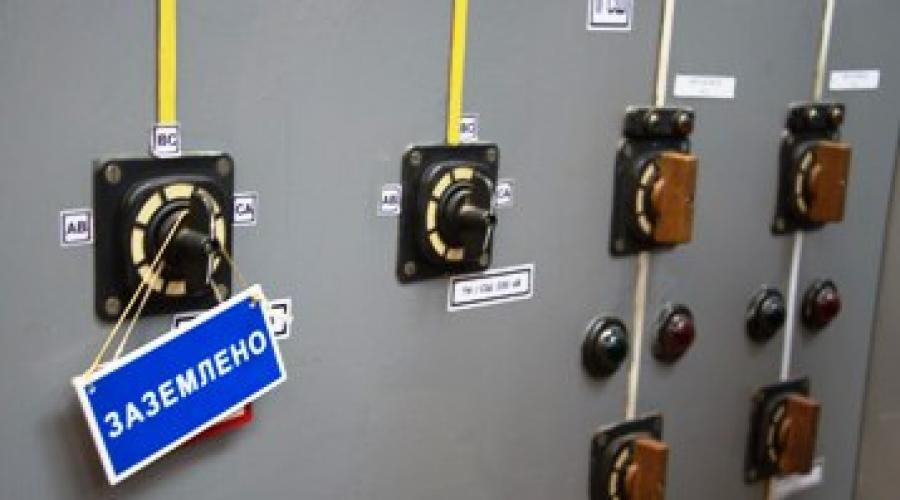
5. Grounding the transformer (switching on stationary grounding blades, installing grounding connections on all sides from which voltage can be supplied).
It should be noted that in the switching form, in addition to basic operations with equipment and switching devices, it is necessary to include test operations. Here are a few basic test operations that must be performed when making operational switches.
Before disconnecting the disconnector, it is necessary to check the open position of the switch of this connection in order to prevent operations with the disconnector under load. In addition, before performing a switching operation, it is necessary to check the integrity of the support and traction insulation of the disconnectors. Very often, the unsatisfactory condition of the insulation of disconnectors leads to accidents.
Likewise, before rolling out or rolling in the switchgear trolley, it is necessary to check the open position of the circuit breaker of a given cell, and also take measures to prevent erroneous or spontaneous activation of the circuit breaker.
When turning off (on) the switch remotely, it is necessary to check its off (on) position according to warning lights and instrument readings (ammeters). There are times when the warning light shows the on position, but in fact the switch is off.
If this is, for example, a sectional switch, then further disconnection of the section's input switch will lead to de-energization of the section, since the sectional switch was not initially turned on. Therefore, it is necessary to check the on (off) position of the switches, both by signal lamps and by the presence (absence) of load.
Before installing grounding on the equipment site, you must ensure that the disconnectors, separators, roll-out trolleys from all sides from which voltage can be applied. Immediately before installing the grounding, the absence of voltage is checked on those live parts on which grounding blades will be connected or portable protective grounding connections will be installed.
After complete completion of the work, if it is necessary to unground and put into operation the equipment taken out for repair, it is imperative to check the readiness of the equipment for commissioning, in particular the absence of short circuits and grounding. Turning equipment on to ground or short leads to accidents and emergency situations.
If it is necessary to re-fix the connection from one bus system to another, it is necessary to check the switched position of the bus coupling switch and its disconnectors from the bus systems. Otherwise, that is, if the SHSV is disabled, the rupture of the bus disconnector fork will occur under load, which is unacceptable.
Before commissioning, after performing operations on the equipment and with switching devices, it is necessary to check the differential current of the DZSh. Putting the DPS into operation with a differential current value greater than the maximum permissible will lead to false alarm this protection and de-energization of the bus system(s).
When removing voltage transformers for repair, as well as transformers feeding low-voltage switchboards, it is necessary to make sure that there is no possibility of supplying voltage through the secondary winding. Combining the secondary windings of a transformer being taken out for repair and a transformer in operation leads to reverse transformation and the appearance of a primary winding at the terminals high voltage, which is potentially dangerous for personnel working on equipment taken out for repair.
Therefore, it is necessary to ensure a visible break not only in the primary chains, but also in the secondary chains. For example, when taking a voltage transformer out for repair, a visible break is ensured by removing the covers of the test blocks, and in their absence, by disconnecting and short-circuiting the secondary windings.
In addition to the operations being performed, the switching form indicates the initial state of the substation circuit and specifically the network section where the switching is performed, as well as the start and end time of the switching.
If it is necessary to perform operations at substations of adjacent networks, for example, withdrawing automatic reclosure at the other end of the line, removing the load and analyzing the circuit on the consumer’s side, it is necessary to include the corresponding item in the switching form.
For example, before grounding the line, write down the following point: “receive confirmation from the duty dispatcher about the disconnection of the line from the consumer side and the possibility of installing grounding.”
The above rules may differ or be supplemented in accordance with the characteristics of a particular electrical installation. Each energy enterprise has appropriate instructions and rules regarding the production of operational switching.
To simplify the preparation of switching forms, as well as to prevent operational errors, in addition to standard switching forms, repair diagrams are drawn up, which provide the sequence of actions when taking out a particular section of the electrical network for repair.
After the switching form has been compiled, it must be checked. If switching is carried out with a supervisory person, then the switching form is additionally checked by the supervisory person.
If the switches are simple and can be performed by an operational worker alone, then the form is checked by a dispatcher who gives the command to make the switches. A list of simple and complex switchings is compiled and approved by the management of the enterprise.

In addition to the above, it should be noted A few guidelines to follow when performing operational switchovers:
Switching should be done in sufficient light;
During operational switching, you cannot conduct extraneous conversations, including being distracted by phone calls;
Before performing an operation with a switching device, you must ensure that the selected connection and piece of equipment is correct;
If doubts arise regarding the correctness of a particular operation, then it is necessary to immediately stop switching and report this to higher operational personnel (dispatcher);
If the electromagnetic lock fails, you must first make sure that the operation is actually performed correctly and that all the necessary conditions to perform this operation. You cannot make hasty conclusions about the malfunction of the electromagnetic locking;
It is prohibited to change the order of operations specified in the switching form;
When performing operational switching, you should use the necessary protective equipment and follow the rules safe operation electrical installations.
All changes in the substation equipment diagram are recorded manually on a layout diagram (mnemonic diagram). If the substation is installed, then the diagram depicted on it is brought into compliance with the current diagram automatically. If for one reason or another the position of the switching devices on the SCADA system diagram does not change automatically, it must be set manually in accordance with the actual state of the equipment. The same applies to portable grounding connections, the installed position of which is not automatically displayed on the SCADA diagram.
Operational switching in emergency situations
If an emergency occurs in an electrical installation, operating personnel must immediately begin making operational switches to restore the normal circuit or eliminate the possibility of damage to equipment and danger to people.
In emergency situations, operating personnel perform switching without switching forms, recording all performed operations in the operational log.
It is allowed to make draft entries during the liquidation of the accident, and after the accident is liquidated, it is necessary to record all the operations performed in strict chronological order in the operational journal. If complex switching operations need to be performed during an emergency, operating personnel can use standard forms for this purpose.
The above measures are aimed at speeding up the elimination of the emergency situation, but this does not mean that you need to act hastily. In the event of an emergency, it is very important to correctly formulate an overall picture of what happened, soberly assess the situation and act slowly and carefully.
Exploitation electrical substations and distribution devices Krasnik V.V.
12.3. Switching forms
12.3. Switching forms
Switching form (usual) is an operational document that provides a strict sequence of operations with switching devices, grounding disconnectors (knives), operational current circuits, relay protection devices, emergency and regime automation, operations to check the absence of voltage, applying and removing portable groundings, hanging and removal of posters, as well as necessary (for the safety of personnel and safety of equipment) inspection operations.
Standard switching form is an operational document that specifies a strict sequence of operations when performing repeated complex switchings in electrical installations of different control levels or different power facilities.
Using switching forms, complex switchings are performed, as well as all switchings (except single ones) on electrical installations that are not equipped locking devices or having faulty locking devices.
In addition to conventional switching forms for repeated complex switchings, standard programs And standard forms switching.
TO complex include switching that requires a strict sequence of operations with switching devices, grounding disconnectors and relay protection devices, emergency and regime automation. When performing the sequence of operations specified in the programs and switching forms, the safety of operating and maintenance personnel is ensured and the occurrence or development of disturbances in the operation of the electrical installation is prevented.
When making complex switchings, replacing forms or switching programs with any other operational documents is not allowed.
For each power plant, substation and electrical installation of distribution power networks, lists of switching types performed using conventional switching forms, standard forms and switching programs are developed, as well as a list of switching types that can be performed without switching forms. Each list indicates the number of operational personnel involved in certain switches.
Lists of complex switchings, approved by the technical managers of the relevant power facilities, are stored at control centers, central (main) control panels of power plants and substations.
Lists of complex switchings are revised when the circuit, composition of equipment, and relay protection and automation devices change.
The usual switching form is drawn up by operational or operational-repair personnel who will carry out the switching, after recording the order in the operational log.
It is allowed to draw up a switching form by the specified personnel in advance during the shift.
Standard switching forms are developed in advance by the personnel of power enterprises in relation to complex switching in the main electrical connection diagram of an electrical installation, in circuits own needs, relay protection and automation devices, taking into account the fact that switching operations containing operations with secondary switching equipment in emergency system automation circuits are among the complex ones.
Standard switching forms are signed at power plants by the heads of electrical shops and their deputies for relay protection and automation; at electrical network enterprises - heads of dispatch services and heads of local relay protection and automation services.
Standard forms for switching to substations are agreed upon with the heads of the relevant dispatch service, in whose operational management the equipment is located, and approved by the chief engineer of the enterprise.
Switching programs (standard programs) are used by operational managers when making switching in electrical installations of different management levels and different power facilities.
The switching program is approved by the head of the dispatch control, who is operationally subordinate to all switched equipment.
The level of detail of programs is taken to correspond to the level of dispatch control.
Persons directly performing switching operations are permitted to use the switching programs of the corresponding dispatcher, supplemented by switching forms.
Standard programs and switching forms are promptly adjusted in case of changes in the main electrical connection diagram of electrical installations associated with the introduction of new equipment, replacement or partial dismantling obsolete equipment, reconstruction of switchgear, as well as when new relay protection and automation devices are switched on or changes in electrical installations.
With planned changes in the circuit and operating modes of the power system and changes in relay protection and automation devices, the production services of power systems, which manage the equipment and relay protection and automation devices, make the necessary changes and additions in advance to standard programs and switching forms at the appropriate levels of operational management.
Switching forms (standard forms) are used by operational dispatch personnel who directly perform switching.
Switching forms establish the order and sequence of operations when carrying out switching in electrical connection diagrams of electrical installations and relay protection and automation circuits.
The switching form (regular and standard) records all operations with switching devices and operational current circuits, operations with relay protection and automation devices (as well as with the power circuits of these devices), operations on turning on and off grounding blades, applying and removing portable groundings, phasing operations equipment, results of inspection of support-rod insulators (presence of cracks and chips) before performing operations with disconnectors, operations with telemechanics devices and others in a certain sequence of their implementation.
The switching forms indicate the most important personnel check actions:
checking the absence of voltage before applying ground connections (turning on grounding blades) to live parts;
on-site check of the switched-on position of the busbar before commencing operations to transfer connections from one bus system to another;
on-site check of the open position of the switch, if the next operation is with disconnectors;
checking on site or using signaling devices the position of each switching device of the primary circuit after the device has performed an operation;
checking at the end of the switchings the compliance of the switching devices in the relay protection and automation circuits with the regime cards.
Each operation (or action) in the switching form is recorded under a serial number.
Immediately before switching using a regular switching form, the correctness of the operations recorded in it is checked using an operational diagram (or layout diagram), which accurately reflects the actual position of the switching devices of the electrical installation at the time of verification.
After checking, the switching form is signed by two persons - those performing the switching and those monitoring them.
When switching is carried out by one person from the operational staff, the correctness of the switching form is controlled by the operational manager who gave the order for the switch, and his name is entered on the form.
At power plants, when the shift supervisor of the electrical shop (as a supervisor) and the electrician on duty (as the one performing the operations) participate in switching operations, the inscription “I authorize switchings” is written on the switching form, signed by the shift supervisor of the power plant.
When using standard switching forms, the following conditions are met:
the decision to use a standard switching form when performing specific operations is made by the person performing the switching and the supervisory person;
the standard switching form indicates for which connections, when performing which task and for which electrical installation diagram it can be used;
Before starting switching, the standard switching form is checked against the operational diagram or layout diagram of the electrical installation by the supervisor. On checking the standard switching form and the correctness of the sequence of operations and check actions set out in it, in the operational log after recording the dispatcher's order for switching, a record is made that the corresponding standard switching form has been checked, corresponds to the diagrams and switching in the sequence specified in it can be performed. It is allowed to make the specified entry in the standard switching form signed by the person performing the operations and the person controlling the switching data;
It is not allowed to use a standard switching form if the electrical installation diagram or the state of the relay protection and automation devices does not correspond to the diagram for which the standard form was drawn up. Operational personnel are not allowed to make changes or additions to the standard switching form if it corresponds to the scheme and specifications;
if changes have occurred in the primary connection diagram or in the electrical installation circuits that exclude the possibility of performing operations on individual items of the standard switching form, or errors are found in it, the operating personnel of the power plant, the substation makes an appropriate entry in the operational log and informs the persons who signed the standard form about this switches, or persons replacing them by position, as well as the operational manager. The use of a standard form in this case is not permitted; a regular switching form is drawn up;
in the case when, when using a standard switching form for carrying out the next operation on a given electrical installation, it is necessary to receive an order from the dispatcher (for example, an order to turn on the grounding blades on a power line that is being switched off), in the standard switching form, before recording this next operation, a note is made “Performed by order of the dispatcher” .
In case of complex switching in electrical installations using conventional and standard switching forms, it is allowed to involve persons from among the employees of local relay protection and automation services assigned to these devices in performing individual operations in relay protection and automation circuits. The relay protection and automation service worker involved in the switching checks the correctness and order of the operations recorded in the switching form, signs the switching form as a participant in the switching and performs the next operations in the relay protection and automation circuits on the orders of the person performing the switching in the primary connection diagram. In this case, orders and messages about their implementation can be transmitted using communication means.
Switching forms (regular and standard) are reporting documents and are strictly accounted for.
Backup copies of operational switching forms (both regular and standard) issued to operational personnel are numbered. The numbers of all backup switching forms issued to operational personnel are recorded in the operational log. When turning in a shift, the numbers of the last used (filled out) forms are indicated. Used switching forms (including damaged ones) are stored in the order of their numbers.
Already used switching forms are stored for at least 10 days.
The correctness of filling out, applying and maintaining reports on switching forms is periodically monitored by the management of the electrical department at power plants and operational personnel in electrical networks.
From book encyclopedic Dictionary(B) author Brockhaus F.A. From the book Great Soviet Encyclopedia (BL) by the author TSB From the book of Aphorisms author Ermishin OlegLouis-Auguste Blanqui (1805-1881) politician One can yield to force, but only one submits without complaint
From the book Operation of Electrical Substations and Switchgears author Krasnik V.V.Chapter 10. The order and sequence of operational switching at substations 10.1. General provisions Switching is a change from one set of connections to another (ST IEC 50(151)-78). The main document regulating the organization and switching order,
From book Big dictionary quotes and catchphrases authorBLANQUI, Louis Auguste (1805–1881), French communist revolutionary, leader of the Paris Commune of 1070 Capital is stolen labor. "Social Criticism" (1869–1870) ? Carlier R. Dictionnaire des citations fran?aises et ?trang?res. – Paris, 1982, p. 93 1071 Neither God nor master. // Ni Dieu, ni ma?tre. Blanca's motto,
From book The World History in sayings and quotes author Dushenko Konstantin VasilievichBLANQUI, Louis Auguste (Blanqui, Louis Auguste, 1805–1881), French revolutionary communist, leader of the Paris Commune91 First, let's cross the river, and then we'll see! Prison notes from the 1850s. (regarding debates about post-revolutionary socialist society)? Gorev B.I. Auguste Blanqui. – M., 1923, p.