Related and unrelated regulation. Regulation of heat supply to consumers. Single-circuit and multi-circuit self-propelled guns
o i i s l i n e viols of bending
Union of Soviets
Socialist
Wrestblick
Automatic dependent certificate no.
Declared on November 11, 1965 (No. 943575/24-6) with the addition of application No.
UDC 621.165.7-546 (088.8) Committee on Affairs of Inventions and Discoveries under the Council of Ministers
V. B. Rubin, G. I. Kuzmin and A. V. Rabinovich;
Chg n,b, All-Union Thermal Engineering Institute named after. F. E. Dzernvzshchsky
Applicant
METHOD FOR REGULATING HEATING TURBINES
There is a known method related regulation heating turbines, in which static autonomy is achieved by installing isodromic (or with low uneven) regulators of each parameter.
This method cannot be used when several objects are working in parallel according to at least one of the parameters, because parallel connection isodromic regulators is unacceptable and, in addition, during parallel operation it is necessary to stabilize not the parameters, but the generalized forces of the objects acting on the parallel parameters. Therefore, when operating turbines in parallel, more the hard way related regulation.
Coupled systems in principle provide not only static but also dynamic control autonomy in all conditions. However, achieving dynamic autonomy in most cases is associated with significant design difficulties, so in real systems, for economic reasons, complete BBTOHQM is rarely ensured. In addition, and from an operational point of view, only in very rare cases is it necessary to strictly observe the dynamic autonomy of the control loops. The transition from simpler uncoupled systems to more complex coupled systems is often dictated only by the impossibility of obtaining static autonomy in known uncoupled control schemes if parallel operation is required on any of the parameters. This transition leads not only to the complication of the scheme. In systems built using the method of coupled regulation, autonomy is achieved parametrically - by selecting the gain coefficients (transmission ratios) of cross connections between regulators. If the transmission ratios are constant, autonomy is not maintained in all modes. In unrelated regulation, autonomy is ensured compensatory (by regulators). In addition, the use connected system regulation significantly complicates the methods of changing the structure of the circuit when transferring the turbine to special modes (for example, to work with back pressure, etc.). Stability issues are resolved satisfactorily with coupled and uncoupled regulation.
The proposed method allows to achieve
25 static autonomy in uncoupled control systems, both in isolated and parallel operation, and thereby eliminates the need to use complex non-compensation coupled control systems in heating turbines.
The essence of the invention lies in the fact that regulators of the derivative (mechanical) power of the turbine and the steam flow rate are introduced into the unconnected speed and pressure control loops as tracking subsystems.
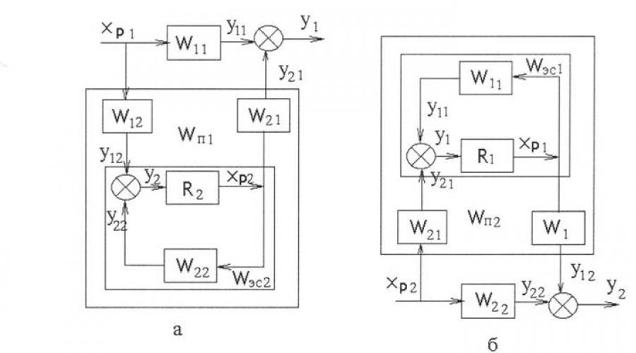
The diagram of the proposed method is shown in the drawing. An executive circuit 2 for regulating the derivative (mechanical) power is introduced into the speed control loop 1 of the turbines, i.e., a generalized control loop inner strength object influencing the system frequency from the side of the turbogenerator.
The power control circuit is made in isodromes. Power regulator 8 receives orders from speed regulator 4, from manual sensor 5, from system regulators o and acts only on the valves high pressure 7, In the pressure control circuit 8, an executive circuit 9 is introduced for stabilizing the steam flow into the selection, i.e., a control circuit for the generalized internal force of the object is also introduced, acting from the turbogenerator on the pressure in the selection. The flow regulator 10 receives tasks from the pressure regulator 11, from the manual set point 12, from the system regulators 18 and affects only the channels low pressure 14.
The rest of the designations adopted in the drawing 1b - the produced (mechanical) power of the turbine, 1b - the steam flow directed by the turbine regulators to the extraction, 17 - we give out the (electrical) power of the generator, 18 - the steam consumption of the thermal consumer, 19 - the frequency (for isolated operation) or the phase angle of the generator (for parallel operation), 20 - pressure in the extraction (for isolated operation) or the pressure difference between the extraction chamber and the consumer (for parallel operation with steam).
When the unit operates in isolation according to the electrical and thermal load, static independence of regulation is ensured in the circuit in the same way as in conventional uncoupled control systems of heating turbines. In case of indignation from the outside heat consumer and moving the low-pressure valves, the speed of the turbogenerator is stabilized by the speed regulator (the power regulator makes this task easier, since it stabilizes the turbine power). In case of disturbance from an electrical consumer5
40 When moving high-pressure valves, the pressure in the outlet is stabilized by a pressure regulator; the flow regulator makes this task easier, as it stabilizes the flow.
Static independence is maintained in the circuit even during parallel operation of the turbogenerator under electrical load and thermal load. In this case, the circuit works as follows. In case of indignation from the outside electrical consumer(frequency change) when manually adjusting high-pressure control valves, a constant pressure in the selection statically maintains the flow regulator. In the event of disturbance from the heat consumer and rearrangement of the low-pressure valves, the constancy of the electrical load is ensured statically by the power regulator. The connections inherent in coupled control circuits (between the speed controller and the low pressure valves and between the pressure regulator and the high pressure valves) are absent in the system. The input of power and flow pulses into the turbine control system can be carried out through electro-hydraulic converters serially produced by turbine-building plants.
In the most common mode of operation of heating turbines - parallel operation of the electrical load and isolated work according to the heat load (on insulated boilers) - the control method is simplified. In this case, the flow control loop 9 is not needed and only a power control loop is introduced.
Using the same principle, instead of pressure and flow control circuits, circuits for regulating the temperature of network water and flow rates can be introduced.
Subject of the invention
Method for regulating heating turbines equipped with unconnected systems regulation of speed and pressure, characterized in that, in order to ensure static autonomy both in isolated and parallel operation, a power control circuit is introduced into the turbine speed control system, and a steam flow control circuit is introduced into the pressure control system into the selection for neutralization of mutual influence of loads in statics.
Compiled by M. Mirimsky
Editor E. A. Krechetova Technical editor A. A. Kamyshnikova Proofreader E. D. Kurdyumova
Order 2527/8 Circulation 1220 Paper format. 60>
TsNIIPI Committee for Inventions and Discoveries under the Council of Ministers of the USSR
Moscow, Center, Serova Ave., 4
Printing house, Sapunova Ave., 2
IZVESTIYA
GOMSK ORDER OF THE RED BANNER OF LABOR POLYTECHNIC
INSTITUTE NAMED AFTER S. M. KIROV
RESEARCH OF THE SYSTEM OF CONNECTED REGULATION OF ONE CLASS OF OBJECTS WITH DISTRIBUTED
PARAMETERS
V. I. KARNACHUK, V. Y. DURNOVTSEV
(Presented by the scientific seminar of the Department of Physics and Technology)
Multiply connected control systems (MCC) are currently finding increasing use in the automation of complex objects. This is due to the fact that complex automation production processes requires a transition from the regulation of one parameter to the associated regulation of several quantities that influence each other. Among similar systems great place are occupied by the same type of installation and installation works, consisting of several identical, identically configured regulators operating from a common source of raw materials or a common load. Multi-channel ACS of objects with distributed parameters, the task of which is to automatically optimize the parameter distribution, can be classified as the same type of SMR. This problem cannot be solved correctly if the mutual influence is not taken into account adjustable parameters. Taking into account mutual influence significantly complicates the analysis of the system, since in a coupled system the dynamics of each parameter is described differential equation high order.
The founder of the theory of regulation of several parameters is I. N. Voznesensky. He showed that in order to eliminate the influence of parameters on each other, it is necessary to introduce artificial connections into the system to compensate for the influence of natural connections. In this case, the connected system turns into an unconnected one, i.e., autonomous. The problem of autonomy is a specific problem that is absent in the theory of one-dimensional ATS. I. N. Voznesensky solved this problem for a first-order plant controlled by an ideal controller. Later, physically and technically feasible conditions for autonomy were found for more complex systems. In these works, the range of objects considered is, as a rule, limited to first-order objects. However, in practice, when researching in the field of regulation of objects with distributed parameters such as distillation column, oil and gas reservoir, vulcanization chambers, various types of reactors, etc., a more complex approximation is often required.
IN this work Some issues of synthesis of two-dimensional SMR of an astatic object with phase advance are considered.
when the object for each controlled variable is described by a second-order differential equation:
t dH dx 2 dt2 dt
koTi -U- +kou. dt
The block diagram of the coupled regulation system is shown in Fig. 1. The system is designed to maintain the specified value of parameter X in two various areas large object.
2 regulator w
Rice. 1. Block diagram of two-dimensional construction and installation work
The object of regulation is a multiply connected system with a ^-structure according to the accepted classification. The transfer functions of objects for each direct channel are equal:
K0(T,p+1) ■
SR) - ^02 (P)
P(T2P+> 1)
The relationship between the adjustable parameters is presented in the block diagram through constant coefficients Li2 = ¿2b, although in the general case it is not time invariant. Integrated regulators with a transfer function are considered:
The regulators receive control signals from inertial sensors (thermocouples) located near the corresponding regulators. Transfer functions of sensors:
Wn(p) = WT2(p) =
Analysis of a coupled system using equations of motion, written even in operator form, is inconvenient due to the high order of the equations. The matrix method of writing equations has much greater convenience, especially for structural synthesis.
In a matrix form of notation, the equation for an object with a Y-structure has the form:
■ WciWcalia^i 1 - W 01^02^12^21
1 - 1^0] 1 - 12^21
a ^ and the column matrices of the controlled and regulating quantities, respectively.
For the controller you can write:
^^(¿y-X). (6)
u%(p)=G 0 [o
5 - transforming matrix of control actions; y is a matrix-column of control actions.
Elements of matrices and 5 can be obtained after simple structural transformations:
p(Tar+\)(TTr+\)
Then the equation of closed SMR can be written in the following form(hereinafter we will assume that the disturbances acting on the system / = 0):
X = (/ + Г0г р)"1 - W оГ р5Г, (7)
where / is the identity matrix.
From (7) we can obtain the characteristic equation of a closed SMR if we equate the determinants of the matrix (/ + WqWp) to zero:
| / + W0WP | = 0. (8)
Sufficient for construction and installation work has not yet been found general criteria stability checks. Determining the roots of the characteristic equation (8) is also a rather cumbersome task, since it can be shown that even in the two-dimensional case it is necessary to solve a tenth order equation. Under such conditions, the use of funds computer technology for calculating construction and installation work is not only desirable, but also necessary. The importance of analogue models is especially great for solving problems of synthesizing construction and installation equipment that have certain specified properties, and, above all, autonomous installation and installation equipment. It is known that the implementation of the conditions of autonomy is often impossible; in any case, for each specific system, finding the conditions of autonomy that could be implemented in fairly simple steps is an independent task. From expression (7) it is clear that the conditions of autonomy are reduced to the diagonalization of the matrix
Ф, = (/ + ^р)-1" wQwps.
In this case, the SMR equations break down into independent equations. Obviously, the matrix Fu will be diagonal only if the matrix W0Wpj, which is the transfer matrix of the open-loop SMR, is diagonal. To implement these conditions, artificial compensating connections, transmission
Rice. 2. Electronic model of autonomous construction and installation work,
the functions of which can be determined from a more convenient for these purposes notation of the matrix equation SMR:
Fu= ^o Gr(5-Fu). (9)
Exists big number options for implementing compensating connections. However, calculations carried out according to equation (9) show that the most convenient option for implementation is block diagram, when cross-connections are imposed between the inputs of the regulator amplifiers. For this case, the transfer functions of the compensating connections have the form:
/Xu (/>) = - №«¿12; K2\(p) = -
Taking into account expression (2) we have: * and (P)<= К21 (р) =
To study two-dimensional SMR, an electronic model of the system was used, assembled on the basis of the EMU-8 analog installation. The diagram of the electronic model of the SMR is shown in Fig. 2. The following numerical values of the parameters were adopted: a;o=10; KuK^/(r == 0.1; Tx = 10 sec; G2 = 0.1 sec; Tt = 0.3 Tg = 0.5 sec/s; I = 0.1 0.9.
Rice. 3. Curves of transient processes in the channels of non-autonomous (a) and autonomous (c) construction and installation works
Studies of the model have shown that a system without compensating connections remains stable up to the value of the relationship ¿ = 0.5. A further increase in L leads to divergent oscillations of the controlled variable. However, even with L<0,5 характер переходного процесса в системе является неудовлетворительным. Полное время успокоения составляет 25-ъЗО сек при максимальном выбросе 50%. Введение перекрестных связей, соответствующих условиям автономности, позволяет резко улучшить качество регулирования.
As can be seen from the graphs (Fig. 3), the sensitivity of each channel to changes in the setting in the adjacent channel is noticeably reduced. The duration of the transient process and the magnitude of the maximum overshoot can be reduced by reducing the gain of the amplifiers of both channels by a factor of 2 compared to the gain adopted for an uncoupled separate system.
1. Autonomy conditions have been found that are realized by simple active CN circuits for SMR of second-order objects - with phase advance.
2. Analysis of complex construction and installation work using analog computers allows you to select the optimal values of construction and installation work parameters.
An electronic model of two-dimensional autonomous construction and installation work has been proposed.” The influence of the magnitude of the relationship on the stability of the system is shown.
LITERATURE
1. M. V. Meerov, Multiply connected control systems. Ed. "Science", 1965.
2. V. T. Morozovsky. “Automation and telemechanics”, 1962, No. 9.
3. M. D. Mezarovich. Multiply connected control systems. Proceedings of the I FAC Congress, Ed. USSR Academy of Sciences, 1961.
Associated control systems include, in addition to the main regulators, additional dynamic compensators. Calculation and adjustment of such systems is much more complicated than single-circuit automated control systems, which prevents their widespread use in industrial automation systems.
Let's consider methods for calculating multiply connected control systems using the example of an object with two inputs and two outputs.
3.1.1.Synthesis of unrelated regulation
The block diagram of the system is presented in Figure 3.1. The transformation of the two-coordinate control system to equivalent single-circuit ACS is given in Figure 3.2.
Figure 3.1 - Block diagram of disconnected control with interconnected coordinates

Figure 3.2 - Conversion of a two-axis control system to equivalent single-circuit ACS
a is the equivalent object for the first controller; b - equivalent object for the second controller.
Let us derive the transfer function of the equivalent object in a single-circuit ASR with controller R1. As you can see, such an object consists of a main control channel and a complex system associated with it in parallel, including a second closed control loop and two cross channels of the object. The transfer function of the equivalent object has the form:
The second term on the right side of equation (7) reflects the influence of the second control loop on the one under consideration and is essentially a corrective amendment to the transfer function of the forward channel.
Similarly, for the second equivalent object we obtain the transfer function in the form:
Based on the formulas, it can be assumed that if at some frequency the module of the correction correction is negligible compared to the amplitude-frequency characteristic of the direct channel, the behavior of the equivalent object at this frequency will be determined by the direct channel.
The most important correction value is at the operating frequency of each circuit. In particular, if the operating frequencies of two control loops co p i and oz p2 are significantly different, then we can expect that their mutual influence will be insignificant, provided:
|W p2 (iω pl)|<< |W 11 (iω pl)| ; (9)
Where |W p2 (iω pl)| = ![]()
The greatest danger is the case when the inertia of direct and cross channels is approximately the same. Let for example, Wn(p)=W12(p)=W21(p)=W22(p)=W(p). Then for equivalent objects, provided that R1(p)=R2(p)=R(p), we obtain the transfer functions:
frequency characteristics
 (11)
(11)
At the stability boundary, according to the Nyquist criterion, we obtain:
![]() or
or ![]() ; (12)
; (12)
Where ![]() =l or |R(iω)|=0.5/|W(iω)|
=l or |R(iω)|=0.5/|W(iω)|
Thus, the setting of the P-regulator, at which the system is on the border of stability, is half that in a single-circuit ASR.
To qualitatively assess the mutual influence of control loops, a complex coupling coefficient is used:
![]() ;(13)
;(13)
which is usually calculated at zero frequency (i.e. in steady-state modes) and at the operating frequencies of the controllers co p i and co P 2. In particular, when w = 0, the value of ks B is determined by the ratio of the gains across the cross and main channels:
VSWR (0)=Ri2 R21 /(R11 R22); (14) If at these frequencies ks B = 0, then the object can be considered as simply connected; at ks B > 1 it is advisable to swap direct and cross channels; 0<кс В <1 расчет одноконтурных АСР необходимо вести по передаточным функциям эквивалентных объектов (7) и (8).
Let's calculate ks B for our option:
kcв = (ki2*k2i)/(k11*k22)=(0.47*0.0085)/(0.015*3.25)~0.11
3.1.2 Linked regulatory systems
Figure 8 shows block diagrams of autonomous automated control systems

Figure 3.3 – block diagrams of autonomous automated control systems
a - compensation of influences from the second regulator in the first control loop;
b - compensation of influences from the first regulator in the second control loop;
c - autonomous two-coordinate control system. Figure Figure 8 - Block diagrams of autonomous automated control systems
When analyzing complex automatic control systems, their structural diagrams, showing the points of application of influences and possible paths of propagation of signals that interact between system elements, become of particular importance.
Structural diagrams consist of the following structural elements:
dynamic, carrying out some functional or operator connection between their input and output signals;
transformative, serving to transform the nature or structure of signals;
comparisons in which signals are subtracted or added;
branch points, at which the signal propagation path branches into several paths leading to different points in the system;
connections or lines of a block diagram indicating the directions of signal propagation;
points of application of influences;
logical, performing logical operations.
We indicated above that any automatic control system, according to the very principle of its operation, always
has at least one feedback that serves to compare the actual and required value of the controlled variable. We agreed to call this kind of feedback the main one.
It should, however, be noted that modern automatic control systems, in addition to the main feedback loops, the number of which is equal to the number of controlled quantities, often have several more auxiliary or local feedback loops. Automatic control systems with one controlled variable, having only one main feedback and no local feedback, are called single-circuit. In single-loop systems, a force applied to any point can bypass the system and return to the original point, following only one bypass path (see Fig. II.8). Automatic control systems that, in addition to one main feedback, have one or more main or local feedbacks are called multi-circuit. Multi-circuit systems are characterized by the fact that in them an impact applied to any point can bypass the system and return to the original point, following several different bypass paths.
As an example of a multi-circuit (double-circuit) automatic control system with one controlled variable, we can cite a servo system in which, in addition to the main feedback, which serves to generate an error signal and is carried out using a selsyn sensor and a selsyn receiver, there is also local feedback; the latter is carried out using a tachogenerator and an RC circuit connected to it, the voltage from the output of which is subtracted from the error signal.
An example of a multi-circuit automatic control system with several controlled variables is an aircraft engine control system, in which the controlled variables can be engine speed, boost pressure, ignition timing, oil temperature, coolant temperature and other values.
The reasons for introducing local feedback into an automatic control system are very different. For example, they are used in correcting elements to convert a signal in accordance with the required control law, in amplifying elements - for linearization, lowering the noise level, lowering the output resistance, in actuating elements - to increase power.
Feedbacks covering several series-connected system elements can be introduced to give them the required dynamic properties.
Multidimensional automatic control systems, i.e. systems with several controlled quantities, are divided into
into systems of unrelated and connected regulation.
Unrelated control systems are those in which regulators designed to regulate various quantities are not connected to each other and can only interact through a common object of regulation. Systems of unrelated regulation, in turn, can be divided into dependent and independent.
Dependent systems of unrelated regulation are characterized by the fact that in them a change in one of the controlled quantities depends on a change in the others. As a result, in such systems the processes of regulation of various controlled quantities cannot be considered independently, in isolation from each other.
An example of a dependent system of unrelated control is an airplane with an autopilot that has independent rudder control channels. Suppose, for example, that an airplane deviates from its intended course. This will cause, thanks to the presence of the autopilot, a deflection of the rudder. When returning to a given course, the angular velocities of both bearing surfaces of the aircraft, and therefore the lifting forces acting on them, will become unequal, which will cause the aircraft to roll. The autopilot will then deflect the ailerons. As a result of rudder and aileron deflections, the aircraft's drag will increase. Therefore, it will begin to lose height, and its longitudinal axis will deviate from the horizontal. In this case, the autopilot will deflect the elevator.
Thus, in the considered example, the processes of regulation of three controlled quantities - course, lateral roll and longitudinal roll - strictly speaking, cannot be considered independent of each other, despite the presence of independent control channels.
An independent system of unrelated regulation is characterized by the fact that in it the change in each of the controlled quantities does not depend on the change in the others, due to which the processes of regulation of various quantities can be considered in isolation from each other. As an example of independent uncoupled control systems, one can often consider the speed control system of a hydraulic turbine and the voltage control system of the synchronous generator it rotates. The regulation processes in these systems are independent, due to the fact that the voltage regulation process usually proceeds many times faster than the speed regulation process.
Systems of coupled regulation are those systems in which regulators of various controlled quantities have mutual connections with each other, interacting between them outside the object of regulation.
A system of coupled regulation is called autonomous if the connections between its constituent regulators
are such that a change in one of the regulated quantities during the regulation process does not cause changes in the remaining regulated quantities.
Cascade control is control in which two or more control loops are connected so that the output of one controller adjusts the setpoint of the other controller.
The figure above is a block diagram that illustrates the concept of cascade control. The blocks in the diagram actually represent the components of two control loops: the master loop, which is made up of control elements A, E, F, and G, and the slave loop, which is made up of control elements A, B C, and D. The output of the master loop controller is the reference (setpoint) for the slave control loop controller. The slave circuit controller produces a control signal for the actuator.
For processes that have significant lag characteristics (capacitance or resistance that slow down changes in a variable), the slave control loop of a cascade system can detect mismatch in the process earlier and thereby reduce the time required to clear the mismatch. We can say that the slave control loop “shares” the delay and reduces the impact of the disturbance on the process.
In a cascade control system, more than one primary sensing element is used, and the controller (in the slave control loop) receives more than one input signal. Therefore, a cascade control system is a multi-loop control system.
Example of a cascade control system

In the example above, the control loop will ultimately be the leading loop when building a cascade control system. The slave circuit will be added later. The purpose of this process is to heat the water passing through the interior of the heat exchanger, flowing around the pipes through which the steam is passed. One of the features of the process is that the heat exchanger body has a large volume and contains a lot of water. A large amount of water has a capacity that allows it to retain a large amount of heat. This means that if the temperature of the water entering the heat exchanger changes, these changes will be reflected at the outlet of the heat exchanger with a long delay. The reason for the delay is the large capacity. Another feature of this process is that the steam pipes resist the transfer of heat from the steam inside the pipes to the water outside the pipes. This means that there will be a lag between changes in steam flow and corresponding changes in water temperature. The reason for this delay is resistance.
The primary element in this control loop controls the temperature of the water leaving the heat exchanger. If the leaving water temperature has changed, the corresponding physical change in the primary element is measured by a transducer, which converts the temperature value into a signal sent to the controller. The controller measures the signal, compares it to the set point, calculates the difference, and then produces an output signal that controls the control valve on the steam line, which is the end element of the control loop (regulator). The steam control valve either increases or decreases the steam flow, allowing the water temperature to return to the set point. However, due to the lag characteristics of the process, the change in water temperature will be slow and it will take a long time before the control loop can read how much the water temperature has changed. By then, too large changes in water temperature may have occurred. As a result, the control loop will generate an excessively strong control action, which can lead to a deviation in the opposite direction (overshoot), and again it will “wait” for the result. Due to a slow response like this, the water temperature may cycle up and down for a long time before settling back to the set point.

The transient response of the control system is improved when the system is supplemented with a second cascade control loop, as shown in the figure above. The added loop is a cascade control slave loop.
Now, when the steam flow changes, these changes will be sensed by the flow sensing element (B) and measured by the transmitter (C), which sends a signal to the slave controller (D). At the same time, the temperature sensor element (E) in the master control loop senses any change in the temperature of the water leaving the heat exchanger. These changes are measured by a measuring transducer (F), which sends a signal to the master controller (G). This controller performs the functions of measurement, comparison, calculation and produces an output signal that is sent to the slave controller (D). This signal corrects the setpoint of the slave controller. The slave controller then compares the signal it receives from the flow sensor (C) with the new setpoint, calculates the difference, and generates a correction signal that is sent to the control valve (A) to adjust the steam flow.
In a control system with the addition of a slave control loop to the main loop, any change in steam flow is immediately sensed by the additional loop. The necessary adjustments are made almost immediately, before the disturbance from the steam flow affects the water temperature. If there are changes in the temperature of the water leaving the heat exchanger, the sensing element perceives these changes and the master control loop adjusts the setpoint of the regulator in the slave control loop. In other words, it sets a set point or "biases" the regulator in the slave control loop so as to adjust the steam flow to achieve the desired water temperature. However, this response of the slave loop controller to changes in steam flow reduces the time required to compensate for disturbances from the steam flow.