Heavy-duty long-range spotlight: assembling a homemade LED portable flashlight with your own hands. Homemade flashlight from an LED strip and a dead screwdriver battery How to make a powerful flashlight with your own hands
Read also
More recently, the word LED was associated only with indicator devices. Since they were quite expensive and emitted only a few colors, they also shone faintly. With the development of technology, the price of LED products has gradually decreased, and the scope of application has expanded rapidly.
Today they are used in various devices and are used almost everywhere where lighting devices are needed. Headlights and lamps in cars are equipped with LEDs; advertising on billboards is highlighted by LED strips. In domestic conditions they are also used no less often.
Reasons to use LEDs
Lanterns were not spared either. Thanks to powerful LEDs, it has become possible to assemble a super-powerful and at the same time quite autonomous flashlight. Such lanterns can emit very strong and bright light over a long distance or over a large area.
In this article we will tell you about the main advantages of high-power LEDs, and we will tell you how to fold an LED flashlight with your own hands. If you have already encountered this, then you will be able to supplement your knowledge; for beginners in this area, the article will answer many questions related to LEDs and flashlights with their use.
If you want to save money by using LED, there are some factors to consider. Since sometimes the price of such a lamp can exceed all the savings. If you have to spend a lot of money and time on maintaining light sources, and the total number of them consumes a lot of electricity, then you should consider whether an LED would be a better replacement.
Compared to conventional lamps, LEDs have a number of advantages that elevate them:
- There is no need for maintenance.
- Significant energy savings, sometimes savings up to 10 times.
- High quality luminous flux.
- Very high service life.
Necessary components
If you decide to assemble an LED flashlight with your own hands, for moving in the dark or for working at night, but don’t know where to start? We will help you with this. The first thing you need to do is find the necessary elements for assembly.
Here is a preliminary list of required parts:
- Light-emitting diode
- Winding wire, 20-30 cm.
- The ferrite ring is approximately 1-.1.5 cm in diameter.
- Transistor.
- 1000 ohm resistor.
Of course, this list needs to be supplemented with a battery, but this is an element that can be easily found in any home and does not require special preparation. You should also select a housing or some kind of base on which the entire circuit will be installed. A good case would be an old, non-working flashlight or one that you are going to modify.
How to assemble it yourself
When assembling the circuit, we will need a transformer, but it was not added to the list. We will make it ourselves from a ferrite ring and wire. This is very simple to do, take our ring and start winding the wire forty-five times, this wire will connect to the LED. We take the next wire, wind it thirty times already, and direct it to the base of the transistor.
The resistor used in the circuit should have a resistance of 2000 ohms, only by using such resistance can the circuit work without failure. When testing the circuit, replace resistor R1 with a similar one with adjustable resistance. Turn on the entire circuit and adjust the resistance of this resistor, adjust the voltage to approximately 25mA.
As a result, you will know what resistance should be at this point, and you will be able to select a suitable resistor with the resistance value you need.
If the circuit is drawn up in full accordance with the above requirements, then the flashlight should work immediately. If it doesn't work, then you may have made the following mistake:
- The ends of the winding are connected in reverse.
- The number of turns does not correspond to what is required.
- If the wound turns are less than 15, then current generation in the transformer ceases.
Assembling a 12 volt LED flashlight
If the amount of light from the flashlight is not enough, then you can assemble a powerful flashlight powered by a 12-volt battery. This flashlight is still portable, but much larger in size.
To assemble the circuit of such a lantern with our own hands, we will need the following parts:
- Plastic pipe, about 5 cm in diameter and PVC glue.
- Threaded fitting for PVC, two pieces.
- Threaded plug.
- Tumblr.
- Actually the LED lamp itself is designed for 12 volts.
- Battery for powering the LED, 12 volts.
Electrical tape, heat shrink tubing and small clamps to keep the wiring in order.
You can make your own battery from small batteries that are used in radio-controlled toys. You may need 8-12 pieces, depending on their power, to give a total of 12 volts.
Solder two wires to the contacts on the light bulb, the length of each should exceed the length of the battery by several centimeters. Everyone is carefully isolated. When connecting the lamp and battery, install the toggle switch so that it is located at the opposite end from the LED lamp.
At the ends of the wires coming from the lamp and from the battery pack, which we made with our own hands, we install special connectors for easy connection. We assemble the entire circuit and check its functionality.
Assembly diagram
If everything works, then we proceed to creating the case. Having cut the required length of the pipe, we insert our entire structure into it. We carefully secure the battery inside with glue so that it does not damage the light bulb during operation.
We install a fitting at both ends, secure it with glue, this way we will protect the lantern from accidental moisture getting inside. Next, we bring our toggle switch to the opposite edge from the lamp, and also carefully secure it. The rear fitting must completely cover the switch with its walls, and when the plug is screwed in, prevent moisture from entering there.
To use, simply unscrew the cap, turn on the flashlight and screw it back tightly.
Price issue
The most expensive thing you will need is a 12 volt LED lamp. It costs about 4-5 dollars. After rummaging through children's old toys, batteries from a broken car will be free for you.
The toggle switch and pipe can also be found in the garage; cuttings of such pipes are always left after repairs. If there are no pipes and batteries, you can ask friends and neighbors or buy them at the store. If you buy absolutely everything, then such a flashlight can cost you about $10.
Summarize
LED technology is gaining more and more popularity. Having good characteristics, they can soon completely displace all competitors in the field of lighting. And assembling a powerful portable flashlight with an LED lamp yourself will not be difficult for you.
For safety and the ability to continue active activities in the dark, a person needs artificial lighting. Primitive people pushed back the darkness by setting fire to tree branches, then they came up with a torch and a kerosene stove. And only after the invention of the prototype of a modern battery by the French inventor George Leclanche in 1866, and the incandescent lamp in 1879 by Thomson Edison, did David Meisel have the opportunity to patent the first electric flashlight in 1896.
Since then, nothing has changed in the electrical circuit of new flashlight samples, until in 1923, Russian scientist Oleg Vladimirovich Losev found a connection between luminescence in silicon carbide and the p-n junction, and in 1990, scientists managed to create an LED with greater luminous efficiency, allowing them to replace a light bulb incandescent The use of LEDs instead of incandescent lamps, due to the low energy consumption of LEDs, has made it possible to repeatedly increase the operating time of flashlights with the same capacity of batteries and accumulators, increase the reliability of flashlights and practically remove all restrictions on the area of their use.
The LED rechargeable flashlight that you see in the photograph came to me for repair with a complaint that the Chinese Lentel GL01 flashlight I bought the other day for $3 does not light, although the battery charge indicator is lit.

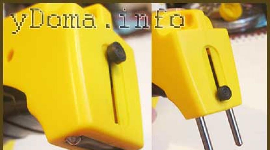
The external inspection of the lantern made a positive impression. High-quality casting of the case, comfortable handle and switch. The plug rods for connecting to a household network for charging the battery are made retractable, eliminating the need to store the power cord.
Attention! When disassembling and repairing the flashlight, if it is connected to the network, you should be careful. Touching exposed parts of a circuit connected to an electrical outlet may result in electric shock.
How to disassemble the Lentel GL01 LED rechargeable flashlight
Although the flashlight was subject to warranty repair, remembering my experiences during the warranty repair of a faulty electric kettle (the kettle was expensive and the heating element in it burned out, so it was not possible to repair it with my own hands), I decided to do the repair myself.

It was easy to disassemble the lantern. It is enough to turn the ring that secures the protective glass a small angle counterclockwise and pull it off, then unscrew several screws. It turned out that the ring is fixed to the body using a bayonet connection.

After removing one of the halves of the flashlight body, access to all its components appeared. On the left in the photo you can see a printed circuit board with LEDs, to which a reflector (light reflector) is attached using three screws. In the center there is a black battery with unknown parameters; there is only a marking of the polarity of the terminals. To the right of the battery there is a printed circuit board for the charger and indication. On the right is a power plug with retractable rods.

Upon closer examination of the LEDs, it turned out that there were black spots or dots on the emitting surfaces of the crystals of all LEDs. It became clear even without checking the LEDs with a multimeter that the flashlight did not light due to their burnout.

There were also blackened areas on the crystals of two LEDs installed as backlight on the battery charging indication board. In LED lamps and strips, one LED usually fails, and acting as a fuse, it protects the others from burning out. And all nine LEDs in the flashlight failed at the same time. The voltage on the battery could not increase to a value that could damage the LEDs. To find out the reason, I had to draw an electrical circuit diagram.
Finding the cause of the flashlight failure
The electrical circuit of the flashlight consists of two functionally complete parts. The part of the circuit located to the left of switch SA1 acts as a charger. And the part of the circuit shown to the right of the switch provides the glow.

The charger works as follows. The voltage from the 220 V household network is supplied to the current-limiting capacitor C1, then to a bridge rectifier assembled on diodes VD1-VD4. From the rectifier, voltage is supplied to the battery terminals. Resistor R1 serves to discharge the capacitor after removing the flashlight plug from the network. This prevents electric shock from capacitor discharge in the event of your hand accidentally touching two pins of the plug at the same time.
LED HL1, connected in series with current-limiting resistor R2 in the opposite direction with the upper right diode of the bridge, as it turns out, always lights up when the plug is inserted into the network, even if the battery is faulty or disconnected from the circuit.
The operating mode switch SA1 is used to connect separate groups of LEDs to the battery. As you can see from the diagram, it turns out that if the flashlight is connected to the network for charging and the switch slide is in position 3 or 4, then the voltage from the battery charger also goes to the LEDs.

If a person turns on the flashlight and discovers that it does not work, and, not knowing that the switch slide must be set to the “off” position, about which nothing is said in the flashlight’s operating instructions, connects the flashlight to the network for charging, then at the expense If there is a surge voltage at the output of the charger, the LEDs will receive a voltage significantly higher than the calculated voltage. A current that exceeds the permissible current will flow through the LEDs and they will burn out. As an acid battery ages due to sulfation of the lead plates, the battery charge voltage increases, which also leads to LED burnout.
Another circuit solution that surprised me was the parallel connection of seven LEDs, which is unacceptable, since the current-voltage characteristics of even LEDs of the same type are different and therefore the current passing through the LEDs will also not be the same. For this reason, when choosing the value of resistor R4 based on the maximum permissible current flowing through the LEDs, one of them may overload and fail, and this will lead to an overcurrent of parallel-connected LEDs, and they will also burn out.
Rework (modernization) of the electrical circuit of the flashlight
It became obvious that the failure of the flashlight was due to errors made by the developers of its electrical circuit diagram. To repair the flashlight and prevent it from breaking again, you need to redo it, replacing the LEDs and making minor changes to the electrical circuit.

In order for the battery charge indicator to actually signal that it is charging, the HL1 LED must be connected in series with the battery. To light an LED, a current of several milliamps is required, and the current supplied by the charger should be about 100 mA.
To ensure these conditions, it is enough to disconnect the HL1-R2 chain from the circuit in the places indicated by red crosses and install in parallel with it an additional resistor Rd with a nominal value of 47 Ohms and a power of at least 0.5 W. The charge current flowing through Rd will create a voltage drop across it of about 3 V, which will provide the necessary current for the HL1 indicator to light. At the same time, the connection point HL1 and Rd must be connected to pin 1 of switch SA1. In this simple way, it will be impossible to supply voltage from the charger to the LEDs EL1-EL10 while charging the battery.
To equalize the magnitude of the currents flowing through the LEDs EL3-EL10, it is necessary to exclude resistor R4 from the circuit and connect a separate resistor with a nominal value of 47-56 Ohms in series with each LED.
Electrical diagram after modification
Minor changes made to the circuit increased the information content of the charge indicator of an inexpensive Chinese LED flashlight and greatly increased its reliability. I hope that LED flashlight manufacturers will make changes to the electrical circuits of their products after reading this article.

After modernization, the electrical circuit diagram took the form as in the drawing above. If you need to illuminate the flashlight for a long time and do not require high brightness of its glow, you can additionally install a current-limiting resistor R5, thanks to which the operating time of the flashlight without recharging will double.
LED battery flashlight repair
After disassembly, the first thing you need to do is restore the functionality of the flashlight, and then start upgrading it.

Checking the LEDs with a multimeter confirmed that they were faulty. Therefore, all the LEDs had to be desoldered and the holes freed from solder to install new diodes.

Judging by its appearance, the board was equipped with tube LEDs from the HL-508H series with a diameter of 5 mm. LEDs of type HK5H4U from a linear LED lamp with similar technical characteristics were available. They came in handy for repairing the lantern. When soldering LEDs to the board, you must remember to observe polarity; the anode must be connected to the positive terminal of the battery or battery.
After replacing the LEDs, the PCB was connected to the circuit. The brightness of some LEDs was slightly different from others due to the common current-limiting resistor. To eliminate this drawback, it is necessary to remove resistor R4 and replace it with seven resistors, connected in series with each LED.
To select a resistor that ensures optimal operation of the LED, the dependence of the current flowing through the LED on the value of the series-connected resistance was measured at a voltage of 3.6 V, equal to the voltage of the flashlight battery.
Based on the conditions for using the flashlight (in case of interruptions in the power supply to the apartment), high brightness and illumination range were not required, so the resistor was chosen with a nominal value of 56 Ohms. With such a current-limiting resistor, the LED will operate in light mode, and energy consumption will be economical. If you need to squeeze out maximum brightness from the flashlight, then you should use a resistor, as can be seen from the table, with a nominal value of 33 Ohms and make two modes of operation of the flashlight by turning on another common current-limiting resistor (in the diagram R5) with a nominal value of 5.6 Ohms.

To connect a resistor in series with each LED, you must first prepare the printed circuit board. To do this, you need to cut any one current-carrying path on it, suitable for each LED, and make additional contact pads. The current-carrying paths on the board are protected by a layer of varnish, which must be scraped off with a knife blade to the copper, as in the photograph. Then tin the bare contact pads with solder.
It is better and more convenient to prepare a printed circuit board for mounting resistors and soldering them if the board is mounted on a standard reflector. In this case, the surface of the LED lenses will not be scratched, and it will be more convenient to work.

Connecting the diode board after repair and modernization to the flashlight battery showed that the brightness of all LEDs was sufficient for illumination and the same brightness.

Before I had time to repair the previous lamp, the second one was repaired, with the same fault. I didn’t find any information about the manufacturer or technical specifications on the flashlight body, but judging by the manufacturing style and the cause of the breakdown, the manufacturer is the same, Chinese Lentel.

Based on the date on the flashlight body and on the battery, it was possible to establish that the flashlight was already four years old and, according to its owner, the flashlight worked flawlessly. It is obvious that the flashlight lasted a long time thanks to the warning sign “Do not turn on while charging!” on a hinged lid covering a compartment in which a plug is hidden for connecting the flashlight to the mains for charging the battery.

In this flashlight model, the LEDs are included in the circuit according to the rules; a 33 Ohm resistor is installed in series with each one. The resistor value can be easily recognized by color coding using an online calculator. A check with a multimeter showed that all the LEDs were faulty, and the resistors were also broken.
An analysis of the cause of the failure of the LEDs showed that due to sulfation of the acid battery plates, its internal resistance increased and, as a result, its charging voltage increased several times. During charging, the flashlight was turned on, the current through the LEDs and resistors exceeded the limit, which led to their failure. I had to replace not only the LEDs, but also all the resistors. Based on the above-mentioned operating conditions of the flashlight, resistors with a nominal value of 47 Ohms were chosen for replacement. The resistor value for any type of LED can be calculated using an online calculator.
Redesign of the battery charging mode indication circuit
The flashlight has been repaired, and you can begin making changes to the battery charging indication circuit. To do this, it is necessary to cut the track on the printed circuit board of the charger and indication in such a way that the HL1-R2 chain on the LED side is disconnected from the circuit.

The lead-acid AGM battery was deeply discharged, and an attempt to charge it with a standard charger was unsuccessful. I had to charge the battery using a stationary power supply with a load current limiting function. A voltage of 30 V was applied to the battery, and at the first moment it consumed only a few mA of current. Over time, the current began to increase and after a few hours increased to 100 mA. After fully charging, the battery was installed in the flashlight.
Charging deeply discharged lead-acid AGM batteries with increased voltage as a result of long-term storage allows you to restore their functionality. I have tested the method on AGM batteries more than a dozen times. New batteries that do not want to be charged from standard chargers are restored to almost their original capacity when charged from a constant source at a voltage of 30 V.
The battery was discharged several times by turning on the flashlight in operating mode and charged using a standard charger. The measured charge current was 123 mA, with a voltage at the battery terminals of 6.9 V. Unfortunately, the battery was worn out and was enough to operate the flashlight for 2 hours. That is, the battery capacity was about 0.2 Ah and for long-term operation of the flashlight it is necessary to replace it.

The HL1-R2 chain on the printed circuit board was successfully placed, and it was necessary to cut only one current-carrying path at an angle, as in the photograph. The cutting width must be at least 1 mm. Calculation of the resistor value and testing in practice showed that for stable operation of the battery charging indicator, a 47 Ohm resistor with a power of at least 0.5 W is required.

The photo shows a printed circuit board with a soldered current-limiting resistor. After this modification, the battery charge indicator lights up only if the battery is actually charging.
Modernization of the operating mode switch
To complete the repair and modernization of the lights, it is necessary to resolder the wires at the switch terminals.
In models of flashlights being repaired, a four-position slide-type switch is used to turn on. The middle pin in the photo shown is general. When the switch slide is in the extreme left position, the common terminal is connected to the left terminal of the switch. When moving the switch slide from the extreme left position to one position to the right, its common pin is connected to the second pin and, with further movement of the slide, sequentially to pins 4 and 5.

To the middle common terminal (see photo above) you need to solder a wire coming from the positive terminal of the battery. Thus, it will be possible to connect the battery to a charger or LEDs. To the first pin you can solder the wire coming from the main board with LEDs, to the second you can solder a current-limiting resistor R5 of 5.6 Ohms to be able to switch the flashlight to an energy-saving operating mode. Solder the conductor coming from the charger to the rightmost pin. This will prevent you from turning on the flashlight while the battery is charging.
Repair and modernization
LED rechargeable spotlight "Foton PB-0303"
I received another copy of a series of LED flashlights made in China called LED spotlight “Photon PB-0303” for repair. The flashlight did not respond when the power button was pressed; an attempt to charge the flashlight battery using a charger was unsuccessful.

The flashlight is powerful, expensive, costs about $20. According to the manufacturer, the luminous flux of the flashlight reaches 200 meters, the body is made of impact-resistant ABS plastic, and the kit includes a separate charger and a shoulder strap.

The Photon LED flashlight has good maintainability. To gain access to the electrical circuit, simply unscrew the plastic ring holding the protective glass, rotating the ring counterclockwise when looking at the LEDs.

When repairing any electrical appliances, troubleshooting always starts with the power source. Therefore, the first step was to measure the voltage at the terminals of the acid battery using a multimeter turned on in mode. It was 2.3 V, instead of the required 4.4 V. The battery was completely discharged.
When connecting the charger, the voltage at the battery terminals did not change, it became obvious that the charger was not working. The flashlight was used until the battery was completely discharged, and then it was not used for a long time, which led to a deep discharge of the battery.

It remains to check the serviceability of the LEDs and other elements. To do this, the reflector was removed, for which six screws were unscrewed. On the printed circuit board there were only three LEDs, a chip (chip) in the form of a droplet, a transistor and a diode.

Five wires went from the board and battery into the handle. In order to understand their connection, it was necessary to disassemble it. To do this, use a Phillips screwdriver to unscrew the two screws inside the flashlight, which were located next to the hole into which the wires went.

To detach the flashlight handle from its body, it must be moved away from the mounting screws. This must be done carefully so as not to tear the wires off the board.

As it turned out, there were no radio-electronic elements in the pen. Two white wires were soldered to the terminals of the flashlight on/off button, and the rest to the connector for connecting the charger. A red wire was soldered to pin 1 of the connector (the numbering is conditional), the other end of which was soldered to the positive input of the printed circuit board. A blue-white conductor was soldered to the second contact, the other end of which was soldered to the negative pad of the printed circuit board. A green wire was soldered to pin 3, the second end of which was soldered to the negative terminal of the battery.
Electrical circuit diagram
Having dealt with the wires hidden in the handle, you can draw an electrical circuit diagram of the Photon flashlight.

From the negative terminal of the battery GB1, voltage is supplied to pin 3 of connector X1 and then from its pin 2 through a blue-white conductor it is supplied to the printed circuit board.
Connector X1 is designed in such a way that when the charger plug is not inserted into it, pins 2 and 3 are connected to each other. When the plug is inserted, pins 2 and 3 are disconnected. This ensures automatic disconnection of the electronic part of the circuit from the charger, eliminating the possibility of accidentally turning on the flashlight while charging the battery.
From the positive terminal of battery GB1, voltage is supplied to D1 (microcircuit-chip) and the emitter of a bipolar transistor type S8550. The CHIP performs only the function of a trigger, allowing a button to turn on or off the glow of EL LEDs (⌀8 mm, glow color - white, power 0.5 W, current consumption 100 mA, voltage drop 3 V.). When you first press the S1 button from the D1 chip, a positive voltage is applied to the base of the transistor Q1, it opens and the supply voltage is supplied to the LEDs EL1-EL3, the flashlight turns on. When you press button S1 again, the transistor closes and the flashlight turns off.
From a technical point of view, such a circuit solution is illiterate, since it increases the cost of the flashlight, reduces its reliability, and in addition, due to the voltage drop at the junction of transistor Q1, up to 20% of the battery capacity is lost. Such a circuit solution is justified if it is possible to adjust the brightness of the light beam. In this model, instead of a button, it was enough to install a mechanical switch.
It was surprising that in the circuit, LEDs EL1-EL3 are connected in parallel to the battery like incandescent light bulbs, without current-limiting elements. As a result, when turned on, a current passes through the LEDs, the value of which is limited only by the internal resistance of the battery and when it is fully charged, the current may exceed the permissible value for the LEDs, which will lead to their failure.
Checking the functionality of the electrical circuit
To check the serviceability of the microcircuit, transistor and LEDs, a 4.4 V DC voltage was applied from an external power source with a current limiting function, maintaining polarity, directly to the power pins of the printed circuit board. The current limit value was set to 0.5 A.

After pressing the power button, the LEDs lit up. After pressing again, they went out. The LEDs and the microcircuit with the transistor turned out to be serviceable. All that remains is to figure out the battery and charger.
Acid battery recovery
Since the 1.7 A acid battery was completely discharged, and the standard charger was faulty, I decided to charge it from a stationary power supply. When connecting the battery for charging to a power supply with a set voltage of 9 V, the charging current was less than 1 mA. The voltage was increased to 30 V - the current increased to 5 mA, and after an hour at this voltage it was already 44 mA. Next, the voltage was reduced to 12 V, the current dropped to 7 mA. After 12 hours of charging the battery at a voltage of 12 V, the current rose to 100 mA, and the battery was charged with this current for 15 hours.

The temperature of the battery case was within normal limits, which indicated that the charging current was not used to generate heat, but to accumulate energy. After charging the battery and finalizing the circuit, which will be discussed below, tests were carried out. The flashlight with a restored battery illuminated continuously for 16 hours, after which the brightness of the beam began to decrease and therefore it was turned off.
Using the method described above, I had to repeatedly restore the functionality of deeply discharged small-sized acid batteries. As practice has shown, only serviceable batteries that have been forgotten for some time can be restored. Acid batteries that have exhausted their service life cannot be restored.
Charger repair
Measuring the voltage value with a multimeter at the contacts of the output connector of the charger showed its absence.

Judging by the sticker pasted on the adapter's body, it was a power supply that produced an unstabilized DC voltage of 12 V with a maximum load current of 0.5 A. There were no elements in the electrical circuit that limited the amount of charging current, so the question arose, why in Did you use a regular power supply as a charger?
When the adapter was opened, a characteristic smell of burnt electrical wiring appeared, which indicated that the transformer winding had burned out.
A continuity test of the primary winding of the transformer showed that it was broken. After cutting the first layer of tape insulating the primary winding of the transformer, a thermal fuse was discovered, designed for an operating temperature of 130°C. Testing showed that both the primary winding and the thermal fuse were faulty.
Repairing the adapter was not economically feasible, since it was necessary to rewind the primary winding of the transformer and install a new thermal fuse. I replaced it with a similar one that was on hand, with a DC voltage of 9 V. The flexible cord with a connector had to be resoldered from a burnt adapter.

The photo shows a drawing of the electrical circuit of a burnt-out power supply (adapter) of the Photon LED flashlight. The replacement adapter was assembled according to the same scheme, only with an output voltage of 9 V. This voltage is quite sufficient to provide the required battery charging current with a voltage of 4.4 V.

Just for fun, I connected the flashlight to a new power supply and measured the charging current. Its value was 620 mA, and this was at a voltage of 9 V. At a voltage of 12 V, the current was about 900 mA, significantly exceeding the load capacity of the adapter and the recommended battery charging current. For this reason, the primary winding of the transformer burned out due to overheating.
Finalization of the electrical circuit diagram
LED rechargeable flashlight "Photon"
To eliminate circuit violations in order to ensure reliable and long-term operation, changes were made to the flashlight circuit and the printed circuit board was modified.

The photo shows the electrical circuit diagram of the converted Photon LED flashlight. Additional installed radio elements are shown in blue. Resistor R2 limits the battery charging current to 120 mA. To increase the charging current, you need to reduce the resistor value. Resistors R3-R5 limit and equalize the current flowing through the LEDs EL1-EL3 when the flashlight is illuminated. The EL4 LED with a series-connected current-limiting resistor R1 is installed to indicate the battery charging process, since the developers of the flashlight did not take care of this.

To install current-limiting resistors on the board, the printed traces were cut, as shown in the photo. The charge current-limiting resistor R2 was soldered at one end to the contact pad, to which the positive wire coming from the charger had previously been soldered, and the soldered wire was soldered to the second terminal of the resistor. An additional wire (yellow in the photo) was soldered to the same contact pad, intended to connect the battery charging indicator.

Resistor R1 and indicator LED EL4 were placed in the flashlight handle, next to the connector for connecting the charger X1. The LED anode pin was soldered to pin 1 of connector X1, and a current-limiting resistor R1 was soldered to the second pin, the cathode of the LED. A wire (yellow in the photo) was soldered to the second terminal of the resistor, connecting it to the terminal of resistor R2, soldered to the printed circuit board. Resistor R2, for ease of installation, could also be placed in the flashlight handle, but since it heats up when charging, I decided to place it in a freer space.
When finalizing the circuit, MLT type resistors with a power of 0.25 W were used, except for R2, which is designed for 0.5 W. The EL4 LED is suitable for any type and color of light.

This photo shows the charging indicator while the battery is charging. Installing an indicator made it possible not only to monitor the battery charging process, but also to monitor the presence of voltage in the network, the health of the power supply and the reliability of its connection.
How to replace a burnt out CHIP
If suddenly a CHIP - a specialized unmarked microcircuit in a Photon LED flashlight, or a similar one assembled according to a similar circuit - fails, then to restore the flashlight's functionality it can be successfully replaced with a mechanical switch.

To do this, you need to remove the D1 chip from the board, and instead of the Q1 transistor switch, connect an ordinary mechanical switch, as shown in the above electrical diagram. The switch on the flashlight body can be installed instead of the S1 button or in any other suitable place.
Repair with modernization
LED flashlight Keyang KY-9914
Site visitor Marat Purliev from Ashgabat shared in a letter the results of repairing the Keyang KY-9914 LED flashlight. In addition, he provided a photograph, diagrams, a detailed description and agreed to publish the information, for which I express my gratitude to him.
Thank you for the article “Do-it-yourself repair and modernization of Lentel, Photon, Smartbuy Colorado and RED LED lights.”

Using examples of repairs, I repaired and upgraded the Keyang KY-9914 flashlight, in which four of the seven LEDs burned out, and the battery life expired. The LEDs burned out due to the switch being toggled while the battery was charging.

In the modified electrical diagram, changes are highlighted in red. I replaced the faulty acid battery with three used Sanyo Ni-NH 2700 AA batteries connected in series, which were on hand.
After reworking the flashlight, the LED consumption current in two switch positions was 14 and 28 mA, and the battery charging current was 50 mA.
Repair and alteration of LED flashlight
14Led Smartbuy Colorado
The Smartbuy Colorado LED flashlight stopped turning on, although three new AAA batteries were installed.

The waterproof body was made of anodized aluminum alloy and had a length of 12 cm. The flashlight looked stylish and was easy to use.
How to check batteries for suitability in an LED flashlight
Repairing any electrical device begins with checking the power source, therefore, despite the fact that new batteries were installed in the flashlight, repairs should begin with checking them. In the Smartbuy flashlight, the batteries are installed in a special container, in which they are connected in series using jumpers. In order to gain access to the flashlight batteries, you need to disassemble it by rotating the back cover counterclockwise.

Batteries must be installed in the container, observing the polarity indicated on it. The polarity is also indicated on the container, so it must be inserted into the flashlight body with the side on which the “+” sign is marked.
First of all, it is necessary to visually check all contacts of the container. If there are traces of oxides on them, then the contacts must be cleaned to a shine using sandpaper or the oxide must be scraped off with a knife blade. To prevent re-oxidation of the contacts, they can be lubricated with a thin layer of any machine oil.
Next you need to check the suitability of the batteries. To do this, touching the probes of a multimeter turned on in DC voltage measurement mode, you need to measure the voltage at the contacts of the container. Three batteries are connected in series and each of them should produce a voltage of 1.5 V, therefore the voltage at the terminals of the container should be 4.5 V.
If the voltage is less than specified, then it is necessary to check the correct polarity of the batteries in the container and measure the voltage of each of them individually. Perhaps only one of them sat down.

If everything is in order with the batteries, then you need to insert the container into the flashlight body, observing the polarity, screw on the cap and check its functionality. In this case, you need to pay attention to the spring in the cover, through which the supply voltage is transmitted to the flashlight body and from it directly to the LEDs. There should be no traces of corrosion on its end.
How to check if the switch is working properly
If the batteries are good and the contacts are clean, but the LEDs do not light, then you need to check the switch.

The Smartbuy Colorado flashlight has a sealed push-button switch with two fixed positions, closing the wire coming from the positive terminal of the battery container. When you press the switch button for the first time, its contacts close, and when you press it again, they open.

Since the flashlight contains batteries, you can also check the switch using a multimeter turned on in voltmeter mode. To do this, you need to rotate it counterclockwise, if you look at the LEDs, unscrew its front part and put it aside. Next, touch the body of the flashlight with one multimeter probe, and with the second touch the contact, which is located deep in the center of the plastic part shown in the photo.
The voltmeter should show a voltage of 4.5 V. If there is no voltage, press the switch button. If it is working properly, then voltage will appear. Otherwise, the switch needs to be repaired.
Checking the health of the LEDs
If the previous search steps failed to detect a fault, then at the next stage you need to check the reliability of the contacts supplying the supply voltage to the board with LEDs, the reliability of their soldering and serviceability.

A printed circuit board with LEDs sealed into it is fixed in the head of the flashlight using a steel spring-loaded ring, through which the supply voltage from the negative terminal of the battery container is simultaneously supplied to the LEDs along the flashlight body. The photo shows the ring from the side it presses against the printed circuit board.

The retaining ring is fixed quite firmly, and it was possible to remove it only with the help of the device shown in the photo. You can bend such a hook from a steel strip with your own hands.

After removing the retaining ring, the printed circuit board with LEDs, which is shown in the photo, was easily removed from the head of the flashlight. The absence of current-limiting resistors immediately caught my eye; all 14 LEDs were connected in parallel and directly to the batteries via a switch. Connecting LEDs directly to a battery is unacceptable, since the amount of current flowing through the LEDs is limited only by the internal resistance of the batteries and can damage the LEDs. At best, it will greatly reduce their service life.

Since all the LEDs in the flashlight were connected in parallel, it was not possible to check them with a multimeter turned on in resistance measurement mode. Therefore, the printed circuit board was supplied with a DC supply voltage from an external source of 4.5 V with a current limit of 200 mA. All LEDs lit up. It became obvious that the problem with the flashlight was poor contact between the printed circuit board and the retaining ring.
Current consumption of LED flashlight
For fun, I measured the current consumption of LEDs from batteries when they were turned on without a current-limiting resistor.

The current was more than 627 mA. The flashlight is equipped with LEDs of type HL-508H, the operating current of which should not exceed 20 mA. 14 LEDs are connected in parallel, therefore, the total current consumption should not exceed 280 mA. Thus, the current flowing through the LEDs more than doubled the rated current.
Such a forced mode of LED operation is unacceptable, as it leads to overheating of the crystal, and as a result, premature failure of the LEDs. An additional disadvantage is that the batteries drain quickly. They will be enough, if the LEDs do not burn out first, for no more than an hour of operation.

The design of the flashlight did not allow soldering current-limiting resistors in series with each LED, so we had to install one common one for all LEDs. The resistor value had to be determined experimentally. To do this, the flashlight was powered from standard batteries and an ammeter was connected to the gap in the positive wire in series with a 5.1 Ohm resistor. The current was about 200 mA. When installing an 8.2 Ohm resistor, the current consumption was 160 mA, which, as tests showed, is quite sufficient for good lighting at a distance of at least 5 meters. The resistor did not get hot to the touch, so any power will do.
Redesign of the structure
After the study, it became obvious that for reliable and durable operation of the flashlight, it is necessary to additionally install a current-limiting resistor and duplicate the connection of the printed circuit board with the LEDs and the fixing ring with an additional conductor.

If previously it was necessary for the negative bus of the printed circuit board to touch the body of the flashlight, then due to the installation of the resistor, it was necessary to eliminate the contact. To do this, a corner was ground off from the printed circuit board along its entire circumference, from the side of the current-carrying paths, using a file.

To prevent the clamping ring from touching the current-carrying tracks when fixing the printed circuit board, four rubber insulators about two millimeters thick were glued onto it with Moment glue, as shown in the photograph. Insulators can be made from any dielectric material, such as plastic or thick cardboard.

The resistor was pre-soldered to the clamping ring, and a piece of wire was soldered to the outermost track of the printed circuit board. An insulating tube was placed over the conductor, and then the wire was soldered to the second terminal of the resistor.


After simply upgrading the flashlight with your own hands, it began to turn on stably and the light beam illuminated objects well at a distance of more than eight meters. Additionally, the battery life has more than tripled, and the reliability of the LEDs has increased many times over.
An analysis of the causes of failure of repaired Chinese LED lights showed that they all failed due to poorly designed electrical circuits. It remains only to find out whether this was done intentionally in order to save on components and shorten the life of the flashlights (so that more people would buy new ones), or as a result of the illiteracy of the developers. I am inclined to the first assumption.
Repair of LED flashlight RED 110
A flashlight with a built-in acid battery from the Chinese manufacturer RED brand was repaired. The flashlight had two emitters: one with a beam in the form of a narrow beam and one emitting diffused light.

The photo shows the appearance of the RED 110 flashlight. I immediately liked the flashlight. Convenient body shape, two modes of operation, a loop for hanging around the neck, a retractable plug for connecting to the mains for charging. In the flashlight, the diffused light LED section was shining, but the narrow beam was not.

To make the repair, we first unscrewed the black ring securing the reflector, and then unscrewed one self-tapping screw in the hinge area. The case easily separated into two halves. All parts were secured with self-tapping screws and were easily removed.

The charger circuit was made according to the classical scheme. From the network, through a current-limiting capacitor with a capacity of 1 μF, voltage was supplied to a rectifier bridge of four diodes and then to the battery terminals. The voltage from the battery to the narrow beam LED was supplied through a 460 Ohm current-limiting resistor.

All parts were mounted on a single-sided printed circuit board. The wires were soldered directly to the contact pads. The appearance of the printed circuit board is shown in the photograph.

10 side light LEDs were connected in parallel. The supply voltage was supplied to them through a common current-limiting resistor 3R3 (3.3 Ohms), although according to the rules, a separate resistor must be installed for each LED.

During an external inspection of the narrow beam LED, no defects were found. When power was supplied through the flashlight switch from the battery, voltage was present at the LED terminals, and it heated up. It became obvious that the crystal was broken, and this was confirmed by a continuity test with a multimeter. The resistance was 46 ohms for any connection of the probes to the LED terminals. The LED was faulty and needed to be replaced.

For ease of operation, the wires were unsoldered from the LED board. After freeing the LED leads from the solder, it turned out that the LED was tightly held by the entire plane of the reverse side on the printed circuit board. To separate it, we had to fix the board in the desktop temples. Next, place the sharp end of the knife at the junction of the LED and the board and lightly hit the knife handle with a hammer. The LED bounced off.
As usual, there were no markings on the LED housing. Therefore, it was necessary to determine its parameters and select a suitable replacement. Based on the overall dimensions of the LED, the battery voltage and the size of the current-limiting resistor, it was determined that a 1 W LED (current 350 mA, voltage drop 3 V) would be suitable for replacement. From the “Reference Table of Parameters of Popular SMD LEDs,” a white LED6000Am1W-A120 LED was selected for repair.

The printed circuit board on which the LED is installed is made of aluminum and at the same time serves to remove heat from the LED. Therefore, when installing it, it is necessary to ensure good thermal contact due to the tight fit of the rear plane of the LED to the printed circuit board. To do this, before sealing, thermal paste was applied to the contact areas of the surfaces, which is used when installing a radiator on a computer processor.

In order to ensure a tight fit of the LED plane to the board, you must first place it on the plane and slightly bend the leads upward so that they deviate from the plane by 0.5 mm. Next, tin the terminals with solder, apply thermal paste and install the LED on the board. Next, press it to the board (it’s convenient to do this with a screwdriver with the bit removed) and warm up the leads with a soldering iron. Next, remove the screwdriver, press it with a knife at the bend of the lead to the board and heat it with a soldering iron. After the solder has hardened, remove the knife. Due to the spring properties of the leads, the LED will be pressed tightly to the board.

When installing the LED, polarity must be observed. True, in this case, if a mistake is made, it will be possible to swap the voltage supply wires. The LED is soldered and you can check its operation and measure the current consumption and voltage drop.
The current flowing through the LED was 250 mA, the voltage drop was 3.2 V. Hence the power consumption (you need to multiply the current by the voltage) was 0.8 W. It was possible to increase the operating current of the LED by decreasing the resistance to 460 Ohms, but I did not do this, since the brightness of the glow was sufficient. But the LED will operate in a lighter mode, heat up less, and the flashlight’s operating time on a single charge will increase.

Testing the heating of the LED after operating for an hour showed effective heat dissipation. It heated up to a temperature of no more than 45°C. Sea trials showed a sufficient illumination range in the dark, more than 30 meters.
Replacing a lead acid battery in an LED flashlight
A failed acid battery in an LED flashlight can be replaced with either a similar acid battery or a lithium-ion (Li-ion) or nickel-metal hydride (Ni-MH) AA or AAA battery.
The Chinese lanterns being repaired were equipped with lead-acid AGM batteries of various sizes without markings with a voltage of 3.6 V. According to calculations, the capacity of these batteries ranges from 1.2 to 2 A×hours.

On sale you can find a similar acid battery from a Russian manufacturer for the 4V 1Ah Delta DT 401 UPS, which has an output voltage of 4 V with a capacity of 1 Ah, costing a couple of dollars. To replace it, simply re-solder the two wires, observing the polarity.
After several years of operation, the Lentel GL01 LED flashlight, the repair of which was described at the beginning of the article, was again brought to me for repair. Diagnostics showed that the acid battery had exhausted its service life.

A Delta DT 401 battery was purchased as a replacement, but it turned out that its geometric dimensions were larger than the faulty one. The standard flashlight battery had dimensions of 21x30x54 mm and was 10 mm higher. I had to modify the flashlight body. Therefore, before buying a new battery, make sure that it will fit into the flashlight body.

The stop in the case was removed and a part of the printed circuit board from which a resistor and one LED had previously been soldered off was cut off with a hacksaw.

After modification, the new battery installed well in the flashlight body and now, I hope, will last for many years.
Replacing a lead acid battery
AA or AAA batteries
If it is not possible to purchase a 4V 1Ah Delta DT 401 battery, then it can be successfully replaced with any three AA or AAA size AA or AAA pen-type batteries, which have a voltage of 1.2 V. For this, it is enough connect three batteries in series, observing polarity, using soldering wires. However, such a replacement is not economically feasible, since the cost of three high-quality AA-size AA batteries may exceed the cost of purchasing a new LED flashlight.
But where is the guarantee that there are no errors in the electrical circuit of the new LED flashlight, and it will not have to be modified either. Therefore, I believe that replacing the lead battery in a modified flashlight is advisable, as it will ensure reliable operation of the flashlight for several more years. And it will always be a pleasure to use a flashlight that you have repaired and modernized yourself.
In my article, I will tell you how to make an insanely bright rechargeable LED flashlight and turn night into day with your own hands.


Show 4 more images


Most of us use flashlights when hiking, for night walks, or simply when going out into the dark. We usually buy these lights at hardware stores, and they shine quite dimly. To fix this, I designed and built a heavy-duty flashlight that is suitable for illuminating the road at night, creating cool photo and video effects (like glowing spheres in science fiction), illuminating a work site and much more, all at a reasonable cost.
Step 1: Materials Used


Show 7 more images


I give a list of the materials I used, you can take the same ones or choose something similar.
- Switches
- Lithium-polymer batteries 11.1V (take those that are more suitable for your flashlight), I give you links to suitable models:
You will also need wires, a terminal block, fuses and fuse holders, solder, heat shrink, etc.
The resulting long-range flashlight will be about three times cheaper than store-bought counterparts. And don't forget that the battery and charger can be used in other devices. Also, while assembling a hand-held lantern, you will gain new knowledge and experience, and this is priceless.
Step 2: Basic operating points for assembling the lantern


Since the diode in our spotlight consumes a huge amount of energy, up to 100 W (33 V and 3 A), it gives off a lot of heat, so it needs a serious heat sink. The one I indicated in my list may seem too big to you, and so it is, but our flashlight itself is “too much”.
To provide energy to this “beast” you will need a powerful battery for devices with high energy consumption, it must also be light and compact, because after all, we are making a portable flashlight - lead-acid ones are immediately eliminated. Lithium polymer batteries meet these requirements. These are usually installed on drones and RC models. They are small, light and can be quickly discharged - just what we need for our flashlight. I installed an 11.1V battery in my flashlight (link above).
Since the battery power is 11.1V, and the diode needs 33V, we took a boost converter. It uses a built-in potentiometer to boost the 11.1V input voltage to 33V output. You must ensure that the diode does not receive more than 34V, and not less than 26V. In order to monitor the output voltage of the converter, you will need a digital volt-ampere meter. It shows you the voltage and current going to the diode. All this allows us to adjust the brightness of the light and helps prevent the current from being supplied at too high a voltage. For additional protection, we will install 4A fuses at the converter output. As fun as it would be to blow up a 100W diode, you don't want to wait for delivery again.
A discharge indicator is necessary to prevent deep discharge, due to the sensitive internal chemistry of lithium polymer batteries, such an indicator is necessary. Each battery cell will be charged at a voltage of up to 4.2V per cell, and not lower than 3V. If the voltage drops below 3V, it will quickly drop to 1V, which will damage the cell. We will prevent this by setting the discharge indicator to 3.2V (a beep will sound) using the button on the top. But if for some unknown reason the voltage drops below 3.2V, quickly charge the battery to the lowest charge level, this will allow the battery cell to be restored with minimal damage.
In my flashlight I installed two switches - one, the main one, for general power, the second - only for the diode. I did this so that when the light is turned off, the cooling system, discharge indicator and digital voltammeter continue to work. This way I can see the battery voltage with the lights on or off, plus I like to hear my unit make noise when the main switch is turned on.
Step 3: Mount the diode to the heat sink


To begin installation, apply thermal paste to the diode as shown in the picture above (since the use of thermal paste has many conflicting reviews, you may not want to do this). After that, I screwed an aluminum heatsink I had lying around onto the diode, and secured them to the large heatsink, like in the other picture above.
Do not tighten the nuts too tightly to avoid bending the diode.
You can glue the reflector lens at this stage using epoxy resin.
Step 4: Body


Show 3 more images


I took the body from an old broken lantern. First I took out its contents - two car headlight bulbs and two small lead acid batteries. I then modified the case a bit to accommodate the new contents. For this I needed: hot glue, epoxy resin, sandpaper and an engraver.
First I removed some of the calipers using an engraver. Then I pre-assembled all the parts and attached the wires to the reflector; I cut off the extra length of wires later. In such cases, epoxy resin always helps. Now I need to try how the assembled parts fit in the case; everything fits perfectly for me. I then cut some vents for the cooler and covered them with a piece of grill from an old broken iPod speaker. I also cut and sanded holes for the digital volt-amp meter, discharge indicator, main switch and trim pot, and installed them and the boost converter using a lot of hot melt glue because it is not visible inside the case.
Then I added a few finishing touches - Velcro on the battery and on the handle of the light so it could be easily attached to something, and applied the stickers that came with the battery. Now it's time to do the wiring.
I don't think everyone will have the luxury of a pre-made flashlight housing, and I'm really interested in how you solve this problem.
Step 5: Wiring


I sketched out a primitive wiring diagram for the lantern. When you wire the light, leave the wires long enough to accommodate the size of the housing. I connected most of the wires before I placed everything in the housing, but you can place the components first and then run the wires through, depending on your flashlight housing.
At this point you will need a terminal block for ground and power connections, wires (12 or 14 US gauge for high power connections), a 4A fuse and fuse holder, and other small items.
Do not forget to hide all connections in heat shrink. First solder the wire to the XT60 connector socket, connect the switch in series with the ground wire, this switch will be the main switch. Then secure the ends to the terminal block, creating a positive and ground line (depending on the terminal block you use, you may have to run wires from each connection to the terminals).
Boost converter
Solder the power and ground wires to the inputs.
Connect the switch to the fuse holder and connect to the negative output. Here we will connect a 4A fuse.
To adjust the voltage going to the diode, you will need access to a potentiometer. For this purpose, I made the trimmer potentiometer already available in the converter available.
Digital voltammeter and diode
Connect two thin wires (red to positive, black to ground) to power the terminal block. Connect the larger diameter black wire to the negative output of the boost converter, after the fuse holder.
The yellow wire will go to the negative output of the diode. The larger red wire will go to the positive output of the boost converter.
Discharge indicator
To connect the discharge indicator, connect the balancing connector to pins from ground to three, cut the grounded wire and connect it to the main ground connector on the terminal block.
Step 6: What not to do


Here is a list of things NOT to do.
Blocking - generator is a generator of short-term pulses repeated at fairly large intervals.
One of the advantages of blocking generators is their comparative simplicity, the ability to connect a load through a transformer, high efficiency, and connection of a sufficiently powerful load.
Blocking oscillators are very often used in amateur radio circuits. But we will run an LED from this generator.
Very often when hiking, fishing or hunting you need a flashlight. But you don’t always have a battery or 3V batteries at hand. This circuit can run the LED at full power from a nearly dead battery.

A little about the scheme. Details: any transistor (n-p-n or p-n-p) can be used in my KT315G circuit.
The resistor needs to be selected, but more on that later.
The ferrite ring is not very large.
And a high-frequency diode with a low voltage drop.
So, I was cleaning out a drawer in my desk and found an old flashlight with an incandescent bulb, burnt out, of course, and recently I saw a diagram of this generator.

And I decided to solder the circuit and put it in a flashlight.
Well, let's get started:

First, let's assemble according to this scheme.

We take a ferrite ring (I pulled it out from the ballast of a fluorescent lamp) and wind 10 turns of 0.5-0.3 mm wire (it could be thinner, but it won’t be convenient). We wound it, make a loop, or a branch, and wind it another 10 turns.
Now we take the KT315 transistor, an LED and our transformer. We assemble according to the diagram (see above). I also placed a capacitor in parallel with the diode, so it glowed brighter.

So they collected it. If the LED does not light, change the polarity of the battery. Still not lit, check that the LED and transistor are connected correctly. If everything is correct and still does not light up, then the transformer is not wound correctly. To be honest, my circuit didn’t work the first time either.
Now we complement the diagram with the remaining details.

By installing diode VD1 and capacitor C1, the LED will glow brighter.

The last stage is the selection of the resistor. Instead of a constant resistor, we put a 1.5 kOhm variable one. And we start spinning. You need to find the place where the LED shines brighter, and you need to find the place where if you increase the resistance even a little, the LED goes out. In my case it is 471 Ohm.
Okay, now closer to the point))
We disassemble the flashlight

We cut a circle from one-sided thin fiberglass to the size of the flashlight tube.
Now we go and look for parts of the required denominations of several millimeters in size. Transistor KT315

Now we mark the board and cut the foil with a stationery knife.
We tinker the board

We fix bugs, if any.
Now to solder the board we need a special tip, if not, it doesn’t matter. We take wire 1-1.5 mm thick. We clean it thoroughly.
Now we wind it on the existing soldering iron. The end of the wire can be sharpened and tinned.

Well, let's start soldering the parts.

You can use a magnifying glass.
Well, everything seems to be soldered, except for the capacitor, LED and transformer.
Now test run. We attach all these parts (without soldering) to the “snot”

Hooray!! Happened. Now you can solder all the parts normally without fear
I suddenly became interested in what the output voltage was, so I measured
LEDs today are built into everything - into toys, lighters, household appliances and even office supplies. But the most useful invention with them is, of course, a flashlight. Most of them are autonomous and produce a powerful glow from small batteries. You won’t get lost in the dark with it, and when working in a dimly lit room, this tool is simply irreplaceable.
Small copies of a wide variety of LED flashlights can be bought in almost any store. They are inexpensive, but the build quality can sometimes be disappointing. Or maybe it’s homemade devices that can be made using the simplest parts. It is interesting, educational and has a developing effect on those who love to make things.
Today we will look at another homemade product - an LED flashlight, made literally from scrap parts. Their cost is no more than a few dollars, and the efficiency of the device is higher than that of many factory models. Interesting? Then do it with us.

How the device works
This time the LED is connected to the battery only through a 3 ohm resistor. Since it contains a ready source of energy, it does not require a storage thyristor and transistor to distribute the voltage, as is the case with the Faraday Eternal Flashlight. An electronic charging module is used to charge the battery. A tiny micromodule provides protection against voltage surges and prevents the battery from overcharging. The device is charged from a USB connector, and on the module itself there is a micro USB connector.Required Parts
- Plastic syringe 20 ml;
- Lenses for LED flashlight with housing;
- Micro button switch;
- 3 Ohm/0.25 W resistor;
- A piece of aluminum plate for the radiator;
- Several copper wires;
- Superglue, epoxy resin or liquid nails.

Assembling a powerful LED flashlight
Preparing an LED with lenses
We take a plastic cap with lenses and mark the circumference of the radiator. It is needed to cool the LED. We mark the mounting grooves and holes on the aluminum plate and cut out the radiator according to the markings. This can be done, for example, using a drill.


We take out the magnifying lenses for a while, they won’t be needed now. Glue the radiator plate onto the back of the cap with superglue. The holes and grooves in the cap and radiator must match.


We tin the LED contacts and solder them with copper wiring. We protect the contacts with heat-shrinkable casings and warm them up with a lighter. We insert an LED with wiring from the front side of the cap.


Processing the flashlight body from a syringe
We unlock the piston with the handle of the syringe; we will no longer need them. We cut the needle cone with a painting knife.We completely clean the end of the syringe, making holes in it for the LED contacts of the flashlight.
We attach the lantern cap to the end surface of the syringe using any suitable glue, for example, epoxy resin or liquid nails. Don’t forget to place the LED contacts inside the syringe.


Connecting the charging micromodule and battery
We attach terminals with contacts to the lithium battery and insert it into the syringe body. We tighten the copper contacts to clamp them with the battery body.
The syringe has only a few centimeters of free space, which is not enough for the charging module. Therefore, it will have to be divided into two parts.
We run a paint knife in the middle of the module board and break it along the cut line. Using double tape we connect both halves of the board together.


We tin the open contacts of the module and solder them with copper wiring.


Final assembly of the flashlight
We solder a resistor to the module board and connect it to the micro-button, insulating the contacts with heat shrink.

We solder the remaining three contacts to the module according to its connection diagram. We connect the micro button last, checking the operation of the LED.