Slinging of scaffolding. Slinging schemes for different types of cargo. Special methods for slinging pipes
TYPICAL TECHNOLOGICAL CARD
SLINGING OF CARGOES FOR VARIOUS PURPOSE
I. SCOPE OF APPLICATION
I. SCOPE OF APPLICATION
1.1. A standard technological map (hereinafter referred to as TTK) is a comprehensive regulatory document that establishes, according to a specific technology, the organization of work processes for the construction of a structure using the most modern means mechanization, progressive designs and methods of performing work. They are designed for some average operating conditions. The TTK is intended for use in the development of Work Performance Projects (WPP), other organizational and technological documentation, as well as for the purpose of familiarizing (training) workers and engineers with the rules for carrying out work on slinging cargo for various purposes.
1.2. This map provides instructions on the organization and technology of work on slinging cargo for various purposes, rational means of mechanization, data on quality control and acceptance of work, requirements industrial safety and labor protection during work.
1.3. The regulatory framework for the development of technological maps is: SNiP, SN, SP, GESN-2001 ENiR, production standards for material consumption, local progressive standards and prices, labor cost standards, material and technical resource consumption standards.
1.4. The purpose of creating the TC is to describe solutions for the organization and technology of work on slinging cargo for various purposes in order to ensure their high quality, as well as:
- reducing the cost of work;
- reduction of construction duration;
- ensuring the safety of work performed;
- organization of rhythmic work;
- rational use labor resources and cars;
- unification of technological solutions.
1.5. On the basis of the TTK, as part of the PPR (as mandatory components of the Work Project), Workers are being developed technological maps(RTK) for execution individual species for slinging cargo for various purposes. Working technological maps are developed on the basis of standard maps for the specific conditions of a given construction organization taking into account its design materials, natural conditions, existing vehicle fleet and building materials, tied to local conditions. Working technological maps regulate the means of technological support and the rules for performing technological processes during the production of work. Design features for slinging cargo for various purposes are decided on a working project basis in each specific case. The composition and degree of detail of materials developed in the RTK are established by the relevant contracting construction organization, based on the specifics and volume of work performed.
Working flow charts are reviewed and approved as part of the PPR by the head of the General Contracting Construction Organization, in agreement with the Customer's organization, the Customer's Technical Supervision.
1.6. The technological map is intended for work producers, foremen and foremen who perform work on slinging cargo for various purposes, as well as the Customer’s technical supervision workers and is designed for specific conditions of work in the third temperature zone.
II. GENERAL PROVISIONS
2.1. The technological map has been developed for a set of works on slinging cargo for various purposes.
2.2. Work on slinging cargo for various purposes is carried out in one shift, the duration of working hours during a shift is:
Where 0.06 is the coefficient of decrease in performance due to increased duration work shift from 8 o'clock to 10 o'clock.
2.3. The work performed sequentially when slinging cargo for various purposes includes:
- selection lifting devices;
- slinging loads and securing guy ropes.
2.4. The technological map provides for the work to be carried out by an integrated mechanized unit with automobile jib crane KS-45717 "Ivanovets"(maximum load capacity 25.0 t, boom length 21.7 m), as a driving mechanism.
Fig.1. Automotive jib crane KS-45717
Fig.2. Chart of crane lifting capacity depending on availability and boom radius
2.5. Work on slinging cargo for various purposes should be carried out in accordance with the requirements of the following regulatory documents:
- SP 48.13330.2011. Organization of construction;
- SNiP 12-03-2001. Occupational safety in construction. Part 1. General requirements;
- SNiP 12-04-2002. Occupational safety in construction. Part 2. Construction production;
- RD 11-05-2007. The procedure for maintaining a general and (or) special log of work performed during construction, reconstruction, major renovation capital construction projects;
- PB 10-14-92*. Rules for the design and safe operation of load-lifting cranes;
________________
* PB 10-14-92 lost force with the introduction of the “Rules for Design and Safe Operation” lifting cranes"(PB 10-382-00).
- RD 10-33-93. Cargo slings general purpose. Requirements for the device and safe operation;
- GOST 25573-82. Cargo rope slings for construction.
III. ORGANIZATION AND TECHNOLOGY OF WORK EXECUTION
3.1. In accordance with SP 48.13330.2001 “Construction Organization”, before the start of unloading and loading work at the site, the Contractor is obliged to obtain from the Customer in the prescribed manner project documentation and permission to carry out construction and installation work. Carrying out work without permission is prohibited.
3.2. Before loading and unloading operations begin, it is necessary to carry out a set of organizational and technical measures, including:
- appoint persons responsible for the quality and safety of work;
- conduct safety training for team members;
- install temporary inventory household premises for storing building materials, tools, equipment, heating workers, eating, drying and storing work clothes, bathrooms, etc.;
- arrange temporary driveways and entrances to the loading area;
- prepare the base of the site for installing the crane;
- provide workers with tools and personal protective equipment;
- prepare places for storing materials, inventory and other necessary equipment;
- protect the loading area with warning signs illuminated at night;
- provide the loading area with fire-fighting equipment and alarm systems;
- draw up an act of readiness of the facility for work;
- obtain permission to carry out work from the Customer’s technical supervision.
3.3. Before loading and unloading operations begin, you must:
- conduct a technical examination of load-handling devices;
- carry out culling of load-handling devices;
- check the completeness of the load-handling devices.
3.3.1. During technical inspection, slings must be subjected to external inspection and tested with a load 1.25 times their rated load capacity.
Slings that have passed acceptance tests at the manufacturer after manufacture are not subject to initial technical examination.
Identified during the inspection or technical examination Damaged slings are removed from service until repairs are carried out.
The results of the inspection of slings are recorded in the registration and inspection log. (For the journal form, see Appendix 5, RD 10-33-93).
3.3.2. Rejection of ropes and chains of slings must be carried out in accordance with the requirements of Article 7.3.28 “Rules for the design and safe operation of load-lifting cranes”.
Rejection of rings, loops and hooks is carried out:
- in the presence of cracks;
- when the surface of elements is worn out or local dents lead to a decrease in area cross section on 10%;
- in the presence of residual deformations leading to a change in the original size of the element by more than 5%.
The following slings are not allowed for use:
- having the defects stated above;
- if the marking tag is missing or damaged;
- with deformed thimbles or when the latter are worn out with a decrease in the original cross-sectional dimensions by more than 15%;
- with cracks on the crimp bushings or when the size of the latter changes by more than 10% of the original;
- with signs of displacement of the rope in the braid or bushings;
- with damaged or missing braids or other protective elements in the presence of protruding ends of the wire at the braiding point;
- with hooks that do not have safety locks.
The manufacturer must guarantee compliance of slings with the requirements of RD 10-33-93, subject to the consumer's compliance with storage and operating conditions.
3.3.3. The sling delivery package should include:
- lanyard with marking tag;
- passport.
The label must indicate:
- serial number of the sling according to the manufacturer’s numbering system;
- lifting capacity of the sling;
- test date (month, year).
The method of attaching the marking tag must ensure its safety until the end of the sling’s operation.
On each element and sling grip in the place established for marking, by stamping or by impact, the following must be applied:
- name of the manufacturer or its trademark;
- symbol of the element or grip according to the manufacturer’s system;
- serial number according to the manufacturer’s numbering system or batch number.
3.3.4. The warranty period for rope slings during single-shift operation is 3 months from the date of commissioning, for chain slings - 18 months.
3.3.5. The completion of preparatory work is recorded in the General Work Log (The recommended form is given in RD 11-05-2007).
3.4. Equipment for loading and unloading steel pipes
3.4.1. It is used for loading and unloading steel pipes using a truck-mounted jib crane. traverses
(see Fig. 3) and end grips
(see Fig. 4) with different load capacities and for different pipe diameters. To prevent damage to the ends of the pipes, the lifting hooks of the traverses and grips are equipped with caprolon pads. The devices must be checked for burrs and distortions on the end grips in contact with the pipe.
Fig.3. Diagram of the TRV-162 traverse with a lifting capacity of 16.0 t
1 - detachable part of the beam; 2 - traverse beam; 3 - earring; 4 - hooks for hanging slings when working with different lengths of pipes; 5 - sling with hook
Fig.4. Scheme of the end gripper ZT-1422 with a lifting capacity of 9.0 t
1 - earring; 2 - sling; 3 - hook; 4 - cheeks; 5 - bracket; 6 - lower caprolon pad; 7 - upper caprolon lining; 8 - cotter pin; 9 - heel
3.4.2. For unloading from pipe carriers insulated pipes and two-pipe sections and their further movement over short distances, pipe-laying cranes equipped with assembly towels
(see Fig. 5) or pincer grips
(see Fig. 6).
Fig.5. Diagram of soft towel PM-1428R with a load capacity of 63.0 tons
1 - towel; 2 - rocker axles; 3 - rocker arm; 4 - axis for hanging on a crane hook
Fig.6. Scheme of pincer gripper ZTA-102 with a lifting capacity of 28.0 tons
1 - earring; 2 - link; 3 - fixation mechanism; 4 - lever; 5 - body; 6 - axis; 7 - foot; 8 - foot axis
3.4.3. The lifting devices used must be branded and labeled indicating the load capacity and test date. In this case, it is necessary to use only such devices that are designed to work with pipes of a given diameter, and monitor their condition during the work.
3.4.4. Persons who must monitor the operation of machines and mechanisms must periodically inspect lifting devices during operation:
- every 10 days - slings;
- every 6 months - traverses.
3.4.5. Load-handling devices for lifting pipes must prevent unintentional release and ensure stability of the load during lifting.
Slingers must be assigned to hook and strap (sling) the load onto the hook of the lifting machine. Other workers (riggers, assemblers, etc.) trained in the profession of slinger in the manner established by the State Mining and Technical Supervision Authority of Russia may be allowed as slingers.
3.4.6. The lifting devices used must be designed only for working with pipes of a given diameter. Slinging of pipes during unloading is carried out by certified slingers.
3.5. To lift building structures, various lifting devices are used in the form of flexible steel ropes, various traverse systems, mechanical and vacuum grips. Load-handling devices must provide simple and convenient slinging and unslinging of elements, reliable engagement or gripping, excluding the possibility of free uncoupling and falling of the load. Load-handling devices must be tested with a test static or dynamic load exceeding their rated load-carrying capacity.
3.5.1. Flexible slings
made from steel ropes. They are used when lifting light columns, beams, slabs, wall panels, containers, etc. Slings are made universal and lightweight depending on the technological purpose - one-, two-, four- and six-legged (Fig. 4). Universal slings are made in the form of closed loops 6...15 m long, made from cables with a diameter of 18...30 mm, lightweight slings - from cables with a diameter of 12...20 mm. Loops on thimbles, hooks or carabiners are installed at the ends. Select the lifting capacity of the sling depending on the weight of the mounting unit.
Fig.7. Flexible slings made from steel ropes
A - flexible slings; b - two-branch rope; c - four-branch rope; 1 - universal sling; 2, 3 - lightweight with hook and loop; 4 - carbines
3.5.2.
Traverses
performed in the form metal beams or triangular welded trusses. At the ends of the lower belt, blocks are installed through which the slings pass. This sling suspension system ensures uniform transmission of forces to all gripping points. Long structures are lifted using traverses. Slinging can be done at two or four points. To lift large-sized structures, spatial traverses are used, and for lifting heavy elements with a shifted center of gravity - traverses with a balancing system. Lightweight slings and grips can be installed on the traverse.
Fig.8. Traverse designs:
A - beam; b - console; c - spatial; 1 - suspension; 2 - flexible rods; 3 - beam; 4 - bracket for suspension to the cargo hook; 5 - block
3.5.3.
Grips
designed for loopless lifting of mounted elements. Structurally, the grippers are mechanical, electromagnetic and vacuum.
With mechanical grippers, the structure is held by frictionally engaging, clamping or picking up protruding parts.
Electromagnetic grippers are based on holding conductive structures using a magnetic field. Such grips are used primarily for installation and loading and unloading of sheet metal structures.
Vacuum grippers are used to lift thin-walled flat designs. The structure is held in place by forces caused by rarefaction of air.
Fig.9. Designs of grippers for loopless installation of elements:
A- friction grip for slinging columns; b- mechanical grip for lifting beams; V- device for slinging slabs; G- fork for mounting ribbed slabs; d- device for slinging structures; e- collet grip; and- pincer grip; h- traverse with vacuum grippers;
1 - mounted structural element; 2 - friction grip beam; 3 - traverse; 4 - mechanical grip; 5 - threaded bracket; 6 - clamp; 7 - fork element; 8, 9 - system of rods for fixation; 10 - wedge liner; 11 - friction sleeve; 12 - pincer grip; 13 - pressure gauge; 14 - vacuum pump; 15 - vacuum cross-beam; 16 - vacuum chamber
3.6. Cargo slinging work includes the following operations:
- moving the crane and installing it in working position on all existing outriggers;
- preparing cargo for slinging;
- selection of removable load-handling devices;
- hanging load-handling devices on a hook;
- inspection and slinging of cargo, and, if necessary, securing guy ropes (for long cargo);
- giving signals to the crane operator;
- loading and unloading cargo with lifting or lowering it and turning the crane boom;
- laying linings and gaskets under structures or parts;
- unslinging the load, uncoupling the guy ropes.
3.6.1. In a certain place, on a prepared site, the person responsible for the safe performance of work with cranes checks the correct installation of the crane in the specified place and then makes an entry in the crane operator’s logbook about permission to carry out the work, putting his signature. Also checks the correct installation of safety signs on the border of the dangerous zone from crane operation and the coordinate protection system.
3.6.2. Hanging lifting devices on the crane hook and removing them from the hook (see Fig. 10) is performed by a worker performing rigging work in the following sequence:
- checks the serviceability of the sling 1
, inspecting it from the load-carrying organs to the ring-bracket;
- takes the ring-clip with both hands 4
, lifts it, dragging the branches of the sling behind it, and puts it on the hook 2
tap;
- checks the correctness of the technique by comparing it with the diagram;
- with both hands, slightly lifts the sling by the ring-bracket and removes it from the hook;
- places the sling on the table.
Fig. 10. Scheme of hanging load-handling devices on a crane hook
1 - ropes (staples); 2 - hook; 3 - latch; 4 - ring-bracket
3.6.3. Preparing loads for slinging and selecting load-handling equipment is carried out in the following sequence:
- the slinger approaches the prefabricated structure and checks whether its quality meets the standards of the tolerance table (surface cleanliness, number of concrete edges and cracks, serviceability of mounting loops and their readiness for slinging, presence of bent reinforcement outlets, concrete sagging on embedded metal parts in grooves and in sockets for mounting loops). If the number of defects exceeds the norm, then the element is rejected;
- if necessary, performs the following: straightens bent reinforcement outlets with an overhead reinforcing wrench, removes concrete deposits using a scarpel and a hammer, additionally cleans embedded parts with a wire brush, removes dirt and ice with a brush, scrapes off with a scraper, sweeps away with a broom;
- checks the markings;
- using tables, determines the mass of the structure;
- depending on the weight of the structure and the slinging scheme, selects a load-handling device;
- goes to the table with lifting equipment and, using the tables, selects slings;
- using the tag, checks the compliance of the selected means with the weight of the load being lifted;
- using the table of permissible defects, checks the suitability of the product for work.
3.6.4. Slinging and lifting of prefabricated structures is carried out in the following sequence:
- the slinger climbs onto the platform where the purlin, beam, etc. lie. cargo;
- gives a signal to the crane operator to bring the slings to the slinging point;
- alternately inserts both hooks of the sling into the throat of the mounting loops with outside parts towards its center of gravity in order to prevent the safety lock from lowering inside the hook;
- moves away from the structure, checks the correctness of the sling and gives the crane operator a signal to tighten the slings;
- checks the quality of the sling and descends from the platform;
- gives a signal to the crane operator to raise the structure by 20...30 cm;
- climbs onto the platform and once again checks the sling and the tension of the slings;
- gives a command to the crane operator to lift the load to a height of 1.0 m;
- after a short pause (20...30 seconds), signals the crane operator about the need to lower the load;
- at a height of 20...30 cm from the surface of the platform, at the command of the worker performing rigging work, the crane operator stops the structure;
- climbs onto the platform, orients and places the structure in place;
- gives a signal to the crane operator to loosen the slings;
- removes the sling hooks from the mounting loops;
- gives the command to the crane operator to lift the slings and move them to the side (raise them to a height of 1.0 m). During lifting, make sure that the hooks do not cling to the loops and protruding parts of the prefabricated element, and keeps the slings from swinging;
- slingers accept the load at a height of up to 1.0 m from the platform (ground) level, orient it in accordance with the storage diagram, and the senior slinger gives a signal to the crane operator to lower the load in such a way that Bottom part the cargo was located from the level of the storage area at a height of 0.4-0.5 m;
- having made sure that the load is correctly oriented above the storage area (stack), the slinger gives a signal to the crane operator to lower the load onto the platform. The slings remain taut. When the load is lowered and the slinger is convinced that the load is in a stable position, the slinger signals the crane operator to loosen the slings;
- then the slinger unslings the load.
STRAPING DIAGRAMS FOR VARIOUS CARGOES
Fig. 11. Slinging structures with flexible slings:
G- slinging with a four-legged sling; d- the same, three-traverse; e- the same, three-block
Fig. 12. Slinging diagrams for pipe assemblies and products
Fig. 13. Slinging diagrams for ball valve units
Fig. 14. Slinging diagrams for crane units with pneumatic-hydraulic drive
Slinger is a sought-after profession. His task is the correct slinging (tying) of the load, giving commands to the crane operator when performing rigging work- lifting, moving, lowering. The work is very responsible. First of all, people’s lives, as well as the safety of the cargo and the performance of the machine depend on correct slinging. For safe conduct technological operations The slinger is required to have certain knowledge, which he receives by completing training and receiving the appropriate certificate.
It is better to entrust the work of moving goods to a professional. But, frankly speaking, almost everyone who has a private house or a dacha, those working in production had to be a slinger. Someone had slabs delivered to their home and needed to be unloaded. Someone ordered a brick concrete fence, septic tank or pipes. Or you urgently need to remove a container or kiosk from the platform. Situations when it is necessary for a non-professional to sling a load arise quite often and basic knowledge they will never interfere here. Even though in such cases, as a rule, the crane operator supervises the loading and unloading.
What types of cargo are there?
Cargoes are classified according to the following criteria:
Type (pieces, bulk, stackable, liquid, gaseous (cylinders))
- weight (lightweight - up to 250 kg; heavy - 0.25-50 tons, very heavy - more than 50 tons)
- size (oversized, oversized, long)
How to properly sling a load?
To perform slinging, you need to know or determine the following parameters of the load: slinging scheme, weight.
Slinging scheme
Stack diagram - a drawing indicating the points and methods of gripping / tying the load. It is handed over to the slinger before starting work. It is prohibited to carry out work without familiarizing yourself with the slinging diagram. Naturally, in private conditions there is not always a slinging scheme and loading/unloading is carried out according to standard rules. Here are some standard schemes slings:
Moving building slabs or blocks is carried out with a hook using specially provided loops. The number of slings must correspond to the number of loops, otherwise the structure may break.
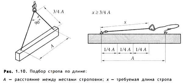
Loads up to 2 meters long can be moved by slinging onto a noose at its center of gravity as in the figure below

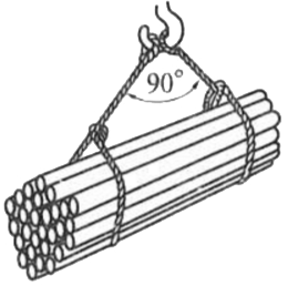
A typical scheme for slinging a long load (logs, pipes, shaped metal products) is carried out using 2 universal USK slings on a noose with a distance from the edge of the load of no more than a quarter of the length of the load. The length of the sling must be at least three quarters of the length of the load, which ensures the maximum permissible angle between the slings less than 90 degrees.
Stropovka sheet metal performed using special clamps or eccentric grips. It is allowed to tie with universal (for example, USK) slings using pads (for example, square wooden blocks, boards)

Slinging of equipment is carried out using specially provided rigging - eye bolts, axles, hinges, hooks, mortgages, etc.
Cargo weight
The weight of the cargo is indicated on the packaging. To perform lifting / rigging work, the parameter used is gross weight (packed). Also, the weight of the cargo can be indicated in the shipping documents. Information about the weight of a product or structure can be obtained from the manufacturer’s website or by telephone. It is prohibited to perform slinging with an unknown mass or if it is a “dead weight” - frozen, buried in the ground, sprinkled, anchored, etc.
Cargo strapping
The tying of the load provides for its capture and movement without the use of embedded elements. There are two main (typical) strapping methods:
Free styling
- “to the noose”
The first method is more gentle on the load and rigging, since it is simply placed between the slings. It can only be used if it is guaranteed that the slings do not have the opportunity to move along the load. To prevent slings from sliding (moving along the load), spacers can be used.
When tying a load “on a noose”, it is clamped with a sling under its own weight. Grabbing the load when correct execution reliable, but there is a possibility of damage to the cargo and the slings wear out more.
When tying long loads (pipes, sheets, timber), you need to take into account that the angle between the slings should not be more than 90 degrees. When gripping a load with sharp edges, special spacers or spacers made from improvised materials are placed at the corners, since there is a possibility of the sling being destroyed and the load falling. You can use a piece of board or timber, rubber of sufficient thickness, etc.
Dependence of the sling's carrying capacity on the tying method
The lifting capacity of the sling, which is indicated on the tag for standard conditions, varies depending on the method of tying the load. The dependency is as follows:
Tightening the load with a loop - minus 20% of the load capacity indicated on the tag
- free laying on 2 slings - plus 100%
- the angle between the branches is 45 degrees. - minus 10%
- the angle between the branches is 90 degrees. - minus 30%
If during tying there are several conditions that change the load capacity, they are summed up. For example, when tightening a long load with 2 loops at an angle between the branches of 45 degrees, for each sling the load capacity should be reduced by (20+30) 50%.
Hooking the load with branch slings
When slinging a load with branch slings, the following rules must be observed:
The size of the hook must be suitable for the size of the loop or eyebolt and fit freely into them. Insert the hook into the loop as shown in the figure below
- the hooks of the slings are installed from the center of gravity of the load
- all loops (eyes) provided by the load manufacturer must be captured by the hook. If the load is not caught on all the provided parts, it may cause damage or breakage.
- 90 degrees - maximum angle between lines
There are three main types of slings - chain, rope and textile. The most vulnerable in terms of exploitation are textile ones. They are not recommended to be used wet in the cold (ice can cause their destruction); they should not be exposed to open fire, concentrated alkalis and acids. To prevent cutting, they must be used very carefully on loads with sharp edges and protected with pads.
It is highly undesirable to carry out work during strong gusts of wind.
To give commands to the crane operator, use special words, having the following designation:
- “vira” - raise
- “mine” - lower it
- “hare” - stop
A huge selection of rigging in the KREPKOM online store - rope, chain, textile slings, lanyards, clamps, thimbles, grips, hooks and other products.
Useful tips
Loads are slinged in accordance with slinging diagrams. To sling a load intended for lifting, slings are used that correspond to the weight and nature of the load being lifted, taking into account the number of branches and their angle of inclination; General purpose slings should be selected so that the angle between the branches does not exceed 90° diagonally.
15.7. Lifting devices are equipped with a brand or firmly attached metal tag indicating the number, load capacity and test date. The load capacity of general purpose slings is calculated at an angle between the branches of 90°, with the exception of ring and single-leg slings, the load capacity of which is given at vertical position. When using ring and single-leg slings in an inclined position for slinging, it is necessary to enter their load capacity correction factor depending on the angle of inclination.
The coefficient is determined by the cosine of the angle alpha formed between the inclined branch of the sling and the vertical. For alpha = 15°, 30°, 45°, the coefficient is respectively equal to 0.966; 0.866; 0.707.
Example. Two ring slings, each with a lifting capacity of 5 tons, are inclined to the vertical at an angle of 45°, therefore load bearing capacity each sling will be equal to 5 tf x 0.707 = 3.535 tf.
15.8. Load-handling devices manufactured for third-party organizations, in addition to the stamp, are supplied with a passport.
15.9. On the container (boxes for solution, bunkers, containers, etc.), in addition to special technological data, its purpose, number, dead weight and carrying capacity are indicated. Safe Operation containers are produced in accordance with GOST 12.3.010-82. The container capacity must prevent the possibility of overloading the machine (crane).
For moving concrete mixture Bunkers (tubs) made in accordance with GOST 21807-76* should be used. Depending on the purpose, the container must meet the relevant regulatory requirements.
15.10. When slinging structures with sharp edges using the strapping method, it is necessary to install gaskets between the edges of the elements and the rope to protect the rope from chafing. The spacers are attached to the load or are permanently attached to the sling as inventory.
15.11. When slinging, the hooks of the slings should be directed away from the center of the load.
15.12. It is prohibited to have faulty or non-standard containers and faulty load-handling devices at the facility under construction.
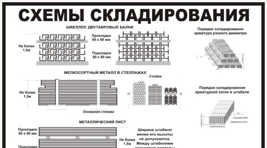
15.13. When developing cargo slinging schemes, it is necessary to take into account the position of cargo during transportation by road, storage of cargo in an on-site warehouse, installation and necessary tilting.
15.14. To store load-handling devices and containers at the construction site, a special place is allocated, where slings are stored in special cabinets or chests, where precipitation does not fall, traverses are stored on special stable stands, and containers are stored on pads.
15.15. Slinging loads from stacks (rolled metal, pipes, timber, etc.) should be carried out in the following sequence:
At the most protruding end of the structure, located in the top row, a loop of a ring sling is put on, hanging on the hook of a two- or four-strand sling;
The slinger moves to a safe distance and gives the command to raise the end of the load to a height of 0.4 - 0.5 m;
The slinger approaches the raised load from the side and places wooden pads with a cross-section of 100 x 100 mm under it at a distance of 1/4 from its ends (when lifting pipes and logs, there should be stops on the pad to prevent the load from rolling out);
The slinger moves to a safe distance and gives the command to lower the load onto the pads and loosen the sling (under safe distance refers to the distance to places that are outside the danger zone at the appropriate lifting height. These places should not be located in the danger zone from the building under construction);
The slinger approaches the load and, using a metal hook (made of wire with a diameter of 6 mm), places ring slings under the load at a distance of 1/4 of the length of the load from its end, then removes the first sling, and tightens the supplied ring slings with a “noose” and puts them on the hooks two- or four-legged sling;
The slinger gives the command to lift the load to a height of 20 - 30 cm, makes sure that the sling is secure and gives the command to further move the load.
15.16. When performing loading and unloading operations at picking depots, slinging of timber laid in bulk should be done using a hydraulic grab or pincer grip.
15.17. Unslinging of structures installed in the design position should be done only after they have been permanently or securely temporarily secured.
15.18. To avoid spontaneous loss of cargo, the container is loaded 100 mm below its sides.
15.19. To install structures at height, it is necessary to use load-handling devices with remote slinging.
15.20. The main provisions for slinging are given on the load slinging diagrams included in the work project.
Slinging diagrams, graphic image methods of slinging and hooking loads should be handed out to slingers and crane operators or posted at work sites. The crane owner or operating organization must also develop methods for tying parts and assemblies of machines moved by cranes during their installation, dismantling and repair, indicating the devices used, as well as methods for safely tilting loads when such an operation is performed using a crane.
Schemes for slinging and tilting loads and a list of used load-handling devices must be given in technological regulations. The movement of cargo for which slinging schemes have not been developed must be carried out in the presence and under the guidance of a person responsible for the safe performance of work with cranes. The management of sea and river ports is obliged to ensure that loading and unloading operations are carried out using cranes in accordance with the technological maps approved by them.
Example of safety posters for lifting operations 

Moving cargo is one of the most complex and critical activities in the production process. In production of all types of industry, the heaviest loads are moved using cranes, but many loads do not have special fastenings for transportation, so intermediate lifting elements are used. Rope and tape slings most often act as such intermediate elements. At our enterprise we produce most types of slings, which you can find in the catalog of our website.
To sling a load intended for lifting, cargo slings must be used that correspond to the weight and nature of the load being lifted, taking into account the number of branches and their angle of inclination. General purpose slings should be selected so that the angle between their branches does not exceed 90°. Depending on the type of sling, the lifting capacity of the slings is recalculated.


Sheet structures and small steel elements lifted and transported to the workplace using grippers and brackets. Steel and reinforced concrete elements (purlins, connections, floor slabs, lintels) are lifted using special traverses that allow multi-tiered arrangement of mounted parts. Crossbars are necessary for uniform load distribution and can be either linear or spatial, depending on the type of load being lifted. During the operation of our enterprise, the design department developed a large number of ready-made traverses, which you can order from us.
To lift and move a package of pipes, round bars or logs, the “noose” slinging method is used. To do this, one end of the sling is threaded through the loop, and the other end of the loop is put on the crane hook so that when lifting, the loop tightens and firmly holds the load suspended. Slinging of a bundle of sheet metal is also done with a universal two-loop sling for a “noose”. The hooks of a two-legged sling are inserted into the free loops, and when they are lifted with the hooks, the universal slings tighten the bundle of metal.
Methods of slinging various materials 


In order to prevent loads from falling during lifting and moving them by cranes, the following slinging rules should be observed:
- When tying the load, the slings must be applied without knots or twists. When moving loads with sharp edges using rope slings, spacers should be placed between the ribs and ropes to protect the latter from damage.
- The ends of a multi-leg sling that are not used for hooking must be strengthened so that when moving the load by crane, the possibility of these ends touching objects encountered on the way is excluded.
- when tying loads chain slings The links on the edges of the load should not be allowed to bend.
- When regularly using rope slings for tying loads with curves, the radii of which are less than 10 rope diameters, it is recommended to reduce the permissible load on the sling branches. When slinging a load and tightening it with a loop of a rope sling, it is recommended to reduce its carrying capacity by 20%.
- movement of loads with their free placement on loop slings is allowed only if there are elements on the load that reliably prevent it from shifting in the longitudinal direction.