Standard pressure gauge scales. Pressure gauges. Pressure units 2 3 from 10 kg pressure gauge scale
In this article we will try to consider in detail all the issues related to pressure gauges, their selection and their operation. We will also consider vacuum gauges and pressure-vacuum gauges together with pressure gauges. All recommendations for these devices are the same, so in the text we will only mention pressure gauges.
1. What is a pressure gauge, vacuum gauge and pressure-vacuum gauge?
2. What types of pressure gauges are there?
3. What parameters are important when choosing a pressure gauge?
4. Conversion of pressure gauge units.
5. How to install pressure gauges?
6. How to use pressure gauges?
7. How are pressure gauges checked?
8. Which pressure gauge is better to buy?
9. What is important to pay attention to when purchasing a pressure gauge?
1. What is a pressure gauge, vacuum gauge and pressure-vacuum gauge?
Technical pressure gauge.
A pressure gauge is a device designed to measure the excess pressure of a working medium through the deformation of a tubular spring (Bourdon tube).

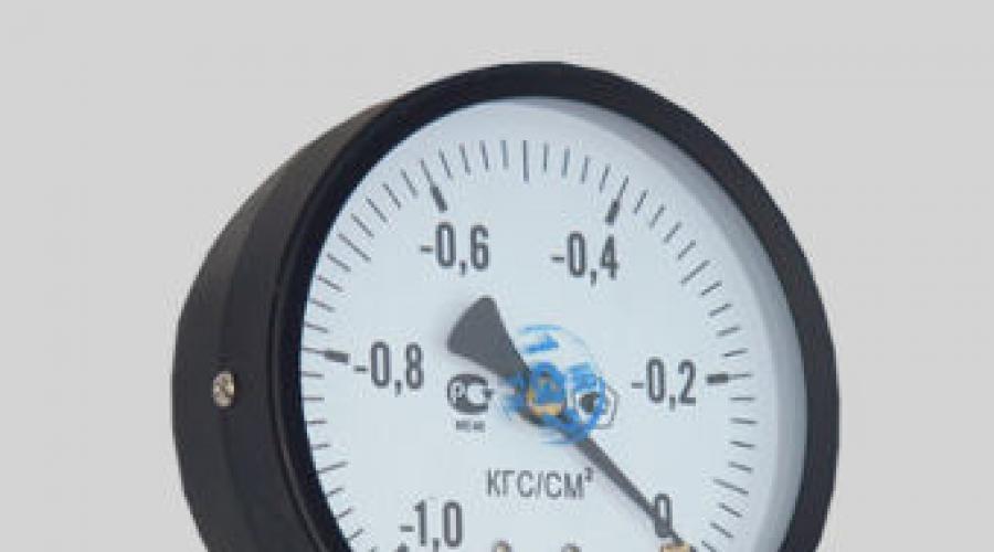
Technical vacuum gauge.
A vacuum gauge is a device designed to measure the vacuum of a working medium through the deformation of a tubular spring. The standard scale for a vacuum gauge is from -1..0 atm. The scale on the vacuum gauge is always negative, since the pressure measured is below atmospheric pressure.

Technical pressure and vacuum gauge.
A pressure vacuum gauge is a device designed to measure excess pressure and vacuum of the working medium through the deformation of a tubular spring.
The above is simple:
- if the instrument scale shows only positive pressure, then it is a pressure gauge.
- if the instrument scale shows only negative pressure, then it is a vacuum gauge.
- if there is both negative and positive pressure on the scale of the device, then it is a pressure and vacuum gauge.
In industry and housing and communal services, pressure gauges with a Bourdon tubular spring are most widely used. This is due to the simplicity of the design and relatively low cost.

Pressure gauge "from the inside".
2. What types of pressure gauges are there?
Technical pressure gauges are the most common instruments for measuring the pressure of water, air, gases, which have been found wide application in the field of housing and communal services and industry. If you do not have any specific requirements for the device, then you should definitely consider technical pressure gauges.
Technical pressure gauge TM610R.
Boiler pressure gauges are technical pressure gauges with a body diameter of 250 mm. These pressure gauges are used when installed at high altitudes or in hard to reach places, which allows you to take readings from a long distance.

Boiler pressure gauge TM810R.
Vibration-resistant pressure gauges are devices for measuring pressure in conditions of increased vibration on a pipeline or installation. These devices are widely used in pumping stations, compressors, cars, ships and trains.

Vibration-resistant pressure gauge TM-320R.
Corrosion-resistant pressure gauges are devices made entirely of stainless steel and designed to work with aggressive environments.
 Corrosion-resistant pressure gauge TM621R.
Welding pressure gauges are devices designed to monitor pressure on oxygen and acetylene reducers, propane cylinders. Welding pressure gauges are oxygen (case color blue), acetylene (case color white or gray) and propane (case color red). On the dial of each device, the type of medium is indicated in a circle.
Precision pressure gauges (example pressure gauges) - devices with a low accuracy class of 0.6 or 0.4 are used for pressure testing of gas pipelines, checking technical pressure gauges, as well as for measuring the pressure of technological lines that require increased measurement accuracy.

Model pressure gauge.
Ammonia pressure gauges are instruments for measuring pressure in refrigeration systems. These devices are manufactured on the basis of corrosion-resistant pressure gauges with a modified dial.

Ammonia pressure and vacuum gauge.
Automotive pressure gauges are devices for measuring air pressure in tires. These devices can be purchased at automobile stores or service centers.

Digital electronic pressure gauges come in two varieties: in a monoblock case and in a set of a pressure transducer and an electronic unit for indicating and adjusting parameters. These devices are used for accurate pressure measurement and in process automation systems.
Electric contact pressure gauges are technical pressure gauges with an electrical contact attachment designed for switching contacts in automation systems.
The fundamental difference between these devices and the entire variety of pressure gauges is the presence of the pressure gauge design parameter. To date, these devices are available in six versions.
3. What parameters are important when choosing a pressure gauge?
In this section, we will look at all the parameters that need to be considered when purchasing a pressure gauge. This is very useful information for buyers who do not have the exact brand of the device or have a brand, but these devices cannot be purchased and need to correctly select analogues.The measuring range is the most important parameter.
Standard range of pressures for pressure gauges:
0-1, 0-1.6, 0-2.5, 0-4, 0-6, 0-10, 0-16, 0-25, 0-40, 0-60, 0-100, 0-160, 0- 250, 0-400, 0-600, 0-1000 kgf/cm2=bar=atm=0.1MPa=100kPa
Standard range of pressures for pressure and vacuum gauges:
-1..+0.6, -1..+1.5, -1..+3, -1..+5, -1..+9, -1..+15, -1..+24 kgf/ cm2=bar=atm=0.1MPa=100kPa
Standard range of pressure gauges:
-1..0 kgf/cm2=bar=atm=0.1MPa=100kPa.
If you don’t know which scale to buy, then choosing a range is quite simple, the main thing is that operating pressure fell in the range from 1/3 to 2/3 of the measurement scale. For example, your pipe usually has a water pressure of 5.5 atm. For stable operation you need to choose a device with a scale of 0-10 atm, because a pressure of 5.5 atm falls in the range from 1/3 to 2/3 of the scale of 3.3 atm and 6.6 atm, respectively. Many people ask the question - what happens if the operating pressure is less than 1/3 of the scale or more than 2/3 of the measurement scale? If the measured pressure is less than 1/3 of the scale, the pressure measurement error will increase sharply. If the measured pressure is more than 2/3 of the scale, then the device mechanism will operate in overload mode and may fail before the warranty period.
Accuracy class is the permissible percentage of measurement error from the measurement scale.
Standard range of accuracy classes for pressure gauges: 4, 2.5, 1.5, 1, 0.6, 0.4, 0.25, 0.15.
How to calculate the pressure gauge error yourself? Let’s say you have a 10 atm pressure gauge with accuracy class 1.5.
This means that the permissible error of the pressure gauge is 1.5% of the measurement scale, i.e. 0.15 atm. If the device error is greater, then the device must be changed. Understand without special equipment Whether the device is working or not, in our experience, is unrealistic.
Only an organization that has a calibration facility with a reference pressure gauge with an accuracy class four times less than the accuracy class of the problematic pressure gauge can make a decision about a discrepancy in the accuracy class. Two instruments are installed in line with the pressure and the two readings are compared.
The diameter of the pressure gauge is an important parameter for pressure gauges in a round case. Standard range of diameters for pressure gauges: 40, 50, 63, 80, 100, 150, 160, 250 mm.
The location of the fitting - there are two varieties: radial, in which the fitting comes out of the pressure gauge from below, and end (rear, axial), in which the connecting fitting is located at the rear of the device.
Connecting thread - greatest distribution On the pressure gauges we found two threads: metric and pipe. Standard range of threads for pressure gauges: M10x1, M12x1.5, M20x1.5, G1/8, G1/4, G1/2. It is used on almost all imported pressure gauges pipe thread. Metric thread used mainly on domestic devices.
The inter-verification interval is the period when it is necessary to re-verify the device. All new devices come with an initial factory verification, which is confirmed by the presence of a verification mark on the dial of the device and a corresponding mark in the passport. On this moment Primary verification can be for 1 year or 2 years. If the pressure gauge is used for personal purposes and verification is not critical, then choose any device. If the pressure gauge is installed at a departmental facility (heating station, boiler room, plant, etc.), then after the end of the initial verification period it is necessary to re-verify the pressure gauge at the CSM (standardization and metrology center) of your city or at any organization that has a license for verification And necessary equipment. For those who are constantly faced with the verification of pressure gauges, it is no secret that very often re-verification is more expensive or comparable to the cost of a new device, and also submitting the device for verification costs money even if the device does not pass re-verification and repair of the device with subsequent verification may be added to the price .
Based on this, we have two recommendations:
- buy devices with initial verification for 2 years, because saving 50-100 rubles on the purchase of a device with a verification period of 1 year can already in a year lead to expenses of 200-300 rubles and unnecessary “running around”.
- before making a decision to re-verify devices, calculate the costs of re-verification - in most cases it is much more profitable to buy new devices. What you need to calculate is the cost of verification, several trips to the verifier. If the system has water hammer, pulsation of the medium (close proximity of pumps), vibration of the pipeline, then after 2 years of operation, usually 50% of the devices do not pass re-verification, and you have to pay for it, because calibration work was carried out.
Operating conditions - if the device will operate in a viscous or aggressive environment, as well as when using the device in difficult conditions - vibration, pulsation, high (more than +100C) and low temperatures (less than -40C), then it is necessary to choose a specialized pressure gauge.
4. Conversion of pressure gauge units.
When purchasing a pressure gauge, there is often a need to measure pressure in non-standard units of measurement. Our work experience says that if we are talking about a small number of devices (less than 100 pieces), then the factories will not change anything on their scales and will have to convert the units of measurement themselves.1kgf/cm2=10.000kgf/m2=1bar=1atm=0.1MPa=100kPa=100.000Pa=10.000mm.water column=750mm. Hg Art. = 1000 mbar
5. How to install pressure gauges?
To install a pressure gauge on a pipe, three-way taps and needle valves are used. Damper blocks, loop taps and diaphragm seals are used to protect pressure gauges.A three-way valve for a pressure gauge is a three-way ball or plug valve designed to connect a pressure gauge to a pipeline or any other equipment. It is possible to install a two-way valve with the ability to manually relieve pressure from the pressure gauge when switched off. The use of standard ball valves is not recommended, because after closing the valve, the pressure gauge mechanism is under residual pressure of the medium, which can lead to its premature failure. Today this is the most common type for connecting pressure gauges at pressures up to 25 kgf/cm2. At high pressures, it is recommended to install needle valves. When purchasing a three-way valve, you need to make sure that the threads on the pressure gauge match the threads on the valve.
A needle valve is a control valve with the ability to smoothly supply a working medium, whose shut-off element is made in the form of a cone. Needle valves are widely used for connecting various instrumentation devices to equipment with high pressures. When purchasing needle valves, you must ensure that the threads on the pressure gauge match the threads on the valve.
The damper block is protective device, which is installed in front of the pressure gauge and is designed to dampen pulsations of the working environment. Under the pulsation in in this case This implies sudden and frequent changes in the pressure of the working environment. The main “organizers” of pulsations in the pipeline are powerful pumps without devices soft start and widespread installation of ball valves and butterfly valves, the rapid opening of which leads to hydraulic shocks.

Damper block.
Loop sampling devices (Perkins tube) are steel tubes that are designed to dampen the temperature in front of pressure gauges. A decrease in the temperature of the medium entering the pressure gauge occurs due to the “stagnation” of the medium in the loop. It is recommended to install these devices at a working environment temperature of more than 80C. There are two types of selection devices: straight and angular. Direct sampling devices are installed on horizontal sections of pipelines, and angular ones are intended for installation on vertical pipelines. Before purchasing, you need to make sure that the threads on the tube match the threads on the three-way valve or pressure gauge.

Selective devices (straight and angular).
Membrane media separators are a protective device for a pressure gauge, designed to protect the device mechanism from aggressive, crystallizing and abrasive media entering it. When choosing a diaphragm seal, you must pay attention to the matching threads on the pressure gauge and the seal.

Membrane separator RM.
When installing pressure gauges, there are several requirements that must be met:
- installation work with a pressure gauge must be done when there is no pressure in the pipeline
- the pressure gauge is installed with vertical arrangement dial
- the pressure gauge is rotated by the fitting using wrench
- it is prohibited to apply force to the pressure gauge body
6. How to use pressure gauges?
When using pressure gauges, you must follow the recommendations and physical parameters(medium temperature and permissible pressure) specified in the device passport. The most important requirement for operation is a smooth supply of pressure to the pressure gauge. If the device is selected correctly and is operated without violations, then there are usually no problems.Let's consider cases in which the operation of a pressure gauge is not allowed:
- when pressure is applied to the device, the needle does not move
- the instrument glass is damaged or broken
- the instrument needle moves irregularly
- after releasing pressure from the device, the needle does not return to zero
- measurement error exceeds the permissible value
7. How are pressure gauges checked?
A pressure gauge is a means of measuring pressure and is subject to mandatory verification. Checking pressure gauges can be divided into two types:- primary verification is a verification that is carried out by the manufacturer before selling the device and is confirmed by the presence of a verification mark on the glass or body of the pressure gauge, as well as a corresponding mark in the device passport. The initial verification is recognized by regulatory organizations without any problems and the device can be used until the end of this period.
Re-verification of the pressure gauge is a verification of the device, which is carried out after the end of the period for the initial verification of the pressure gauge. Before re-checking the pressure gauge, you need to make sure that the device is working properly, because if the device malfunctions, you will receive a nice notification for money comparable to the cost of the device that the device is not working and needs to be repaired or thrown away. Re-verification of the pressure gauge is carried out at the Center for Standardization and Metrology (center for standardization and metrology) in your city or at any organization that has a license for verification and the necessary equipment.
8. Which pressure gauge is better to buy?
Today there are about 10 on the market Russian manufacturers devices, 2 Belarusian manufacturers and a myriad of foreign manufacturers of devices. Let's look at the features of each device.Russian factories are the most optimal choice to buy pressure gauges. Many will ask - why? Everything is quite simple - Russian pressure gauges are significantly cheaper than imported ones with comparable quality, the initial verification period is 2 years, unlike Belarusian ones, a whole line of instruments is produced, from technical to corrosion-resistant.
Belarusian factories are quite cheap devices, but they have 3 significant drawbacks:
- initial verification for 1 year, which turns their cheapness into a “myth” and “running around” with double-checking.
- a simplified mechanism that does not work for a long time under heavy loads.
- plastic glass instead of an instrument one, it also introduces difficulties in the operation and reliability of the device.
Foreign pressure gauges - our many years of experience in trading instruments shows that the point of purchasing is similar to purchasing a Russian instrument, but only 2-3 times more expensive. All explanations from sellers of foreign devices about unique quality, super technologies, etc. are a common ploy to explain to the client why he overpays so steeply. If the operating conditions are difficult, you just need to buy a specialized device instead of a technical one and it will work without problems. If you are tormented by doubts and you have the opportunity to disassemble two similar pressure gauges, Russian and imported, with a screwdriver, then you are unlikely to be lucky in finding several differences.
The exception is highly specialized devices with non-standard scales and parameters, which are not produced in Russia.
9. What is important to pay attention to when purchasing a pressure gauge?
- the pressure gauge must be new. Many instrument sellers understand by the word new that the pressure gauge has not been used. But the pressure gauge may be 15 years old, and they will tell you that it is new. Check the year of manufacture of the device or you may be in for an unpleasant surprise in the form of purchasing an illiquid item.- there must be a mark on the initial verification on the pressure gauge or in the passport. There are sellers of illiquid goods who erase the verifier's mark so that they cannot be accused of selling old devices.
- verification of the pressure gauge must last for 2 years; if you buy a device with initial verification for 1 year, within a year the savings will disappear and unnecessary complications will begin.
- the pressure gauge must have a passport and a valid certificate for measuring instruments.
- if the device is new and verified for 2 years, choose the cheapest option.
- pay attention to the measurement range, scale diameter, type of fitting location, type of thread and design of the device - if you buy the wrong device, then replacing it may be difficult, because if the device has non-standard parameters and is made for you, then most likely you will have to keep it as a keepsake.
- you can search for reviews about pressure gauges on the Internet, but most of them are custom-made and it is better to rely on the advice of people who have experience in actually operating the devices.
- pressure gauges should be bought from an organization that inspires your trust, because the sale of surplus goods from the USSR still exists and then it will be quite difficult to return old instruments or exchange them for normal instruments.
In this article we tried to consider the most popular questions about the whole variety of pressure gauges. If you want other questions to be considered or you do not agree with any answers, write to us and we will try to expand the article based on your experience. In the letter, do not forget to indicate your details, location, conditions and region of installation.
Dear readers!
If you have any useful comments on this article, please write to, indicating the topic of this article.
If you liked this article, please subscribe to our channel.
· 0.6; 1.0; 1.6; 2.5; 4.0
· 6 10 16 25 40
· 60 100 160 250 400
· 600 1000 1600 kgf/cm 2
Ticket number 7
Pressure gauges with single-turn tubular spring OBM
OBM-100; OBM-160 - pressure gauges general purpose;
100, 160 - body diameter in mm.
These devices are the most common. Their advantages: simplicity of the device; reliability in operation; compactness; large measuring range; low cost.
The principle of operation is based on balancing the measured pressure with the force of elastic deformation of the spring.
Under the influence of pressure, the cross-section of the tube tends to take a round shape, as a result of which the tube rotates by an amount proportional to the pressure. When the pressure decreases to atmospheric pressure, the tube returns to its original shape.
The sensitive element (SE) of the pressure gauge is a single-turn tubular spring, which is a tube bent around the circumference with a cross-section in the shape of an oval. The tubular spring is made of bronze, brass or steel, depending on the purpose of the device and the measurement limits.
One end of the tube is soldered into a holder with a fitting, which is designed to connect the pressure gauge to a pressure source.
The second end of the tube is free and hermetically sealed.
A rod is attached to the free end of the tubular spring. The other end of the rod is connected to the shank of the gear sector. The shank of the gear sector has a slot (slide), along which the end of the rod can be moved when adjusting the device.
The toothed sector is held on an axle and meshes with a small gear called a trib. It is rigidly mounted on the arrow axis.
To eliminate the “backlash” of the pointer caused by the presence of backlash in the connections, the pressure gauge is equipped with an elastic spiral-shaped hair made of phosphor bronze. The inner end of the hair is attached to the arrow axis, and the outer end is attached to the stationary part of the device.
Under the influence of pressure inside the tube, its free end moves and pulls the rod along with it. At the same time, the gear sector and the trib, on the axis of which the arrow is mounted, rotate. The end of the arrow shows the measured pressure on the instrument scale.
Rice. 2.4 Spring pressure gauge:
1 – nipple;
2 – holder;
3 - (body) board;
5 – gear (tribe);
6 – spring;
7- Bourdon tube;
8 - sealed end;
9 - gear sector;
10 – arrow;
Depending on their purpose, pressure gauges have the following markings:
MTP, MVTP - vibration-resistant;
SV - ultra-high pressure;
MTI, VTI - precise measurements (accuracy class 0.6; 1.0);
MO, VO - exemplary (class 0.4);
MT, MOSH, OBM - technical.
Ticket No. 9
Selection of pressure gauges according to the permitted
working pressure
The pressure gauge scale must have a red line corresponding to the permitted operating pressure.
The red line is set at 2/3
pressure gauge scales.

Rice. 2.5. Pressure gauge red line
Ticket No. 10
If you need to select a pressure gauge according to the permitted pressure P, then 
and select the nearest one higher value from the manometric series.
Example:
Select the pressure gauge scale if P size = 10 kgf/cm 2

There is no such scale, so the scale is selected from 0 to 16 kgf/cm 2 .
Ticket No. 11
Electric contact pressure gauges
They have an electrical contact device that is activated when a preset pressure is reached and sends a pulse to the signaling devices.
The pressure gauge is equipped with two control arrows with contacts. The control arrows are set to “max” and “min” pressure, and the device arrow, which carries the contacts, moves and gives a signal if the pressure has reached the values set by the control arrows.
ECM - electric contact pressure gauge (used for signaling parameters in explosion-proof rooms);
EKV - electric contact vacuum gauge;
VE-16rb - electric contact pressure gauge, in explosion-proof design.
Ticket No. 12
Pressure control circuit
Some conditions for designating instrumentation and automation equipment:

– a device installed locally (on a pipeline, apparatus);

– a device installed on a panel, console;
P – pressure;
I – indication;
R – registration (record);
T – remote transmission;
V. FITTINGS, CONTROL AND MEASURING INSTRUMENTS, SAFETY DEVICES
5.1. General provisions
5.1.1.To manage work and provide safe conditions During operation, vessels, depending on their purpose, must be equipped with:
shut-off or shut-offgu lining fittings;
devices for measuring pressure;
instruments for measuring temperature;
safety devices;
liquid level indicators.
5. 1. 2. Vessels equipped with b quick release with our lids, we must n We must have safety devices that prevent the vessel from being put under pressure when the lid is not completely closed and opening it when there is pressure in the vessel. Such a vessel s must also be equipped with locks with a key mark.
5.2. Shut-off and shut-off and control valves
5. 2.1.Shut-off and shut-off gu lining fittings must be installed on fittings directly connected To vessel, or on pipelines supplying the vessel and discharging the working medium from it. In the case of a series connection of several vessels, the need to install such fittings between them is determined by the project developer.
5. 2. 2. The fittings must have the following markings:
manufacturer's name or trademark;
nominal diameter, mm;
conditional pressure, MP a (it is allowed to indicate the operating pressure and permissible temperature);
direction of medium flow;
brand of body material.
5. 2. 3. The quantity, type of fittings and installation locations must be selected by the vessel project developer based on specific operating conditions and the requirements of the Rules.
5. 2. 4. On the flywheel shut-off valves the direction of its rotation when opening or closing the valve must be indicated.
5. 2. 5. Vessels for explosive, flammable substances, substances 1st and 2nd hazard class according to GOST 12.1.007-76, as well as evaporators with fire or gas heating must have a check valve on the supply line from the pump or compressor that automatically closes with pressure from the vessel. Check valve must be installed between the pump (compressor) and the shut-off valves of the vessel.
5. 2. 6. Fittings with conditional passage more 20mm, made of alloy steel or non-ferrous metals, must have a passport established form, which should indicate data on the chemical composition, mechanical properties, heat treatment modes and the results of manufacturing quality control using non-destructive methods.
Reinforcement that is marked, but does not have a passport, may be used after an inspection of the reinforcement, testing and verification of the grade of material. In this case, the owner of the valve must draw up a passport.
5.3. Pressure gauges
5. 3.1.Each vessel and independent cavities with different pressures must be equipped with direct-acting pressure gauges V and I. The pressure gauge is installed on the vessel fitting or pipeline between the vessel and the shut-off valve.
5. 3. 2. Pressure gauges must have an accuracy class of at least: 2, 5- at the operating pressure of the vessel up to 2.5 MPa (25 kgf/cm2), 1.5 - when the operating pressure of the vessel is higher 2.5 MPa (25 kgf/cm2).
5. 3. 3. The pressure gauge must be selected with a scale such that the limit for measuring working pressure is in the second third of the scale.
5. 3. 4. The owner of the vessel must mark the pressure gauge scale with a red line indicating the operating pressure in the vessel. Instead of the red line, it is allowed to attach a metal plate painted red to the pressure gauge body and tightly adjacent to the glass of the pressure gauge.
5. 3. 5. The pressure gauge must be installed so that its readings are clearly visible to operating personnel.
5. 3. 6. Nominal diameter of the housing of pressure gauges installed at a height of up to 2m from the level of the observation platform for them, must be at least 100 mm, at a height of 2 to 3 m - at least 160 mm.
Installation of pressure gauges at a height of more than3m from the site level is not permitted.
5. 3. 7. A three-way valve or a device replacing it must be installed between the pressure gauge and the vessel, allowing periodic checking of the pressure gauge using a control valve.
If necessary, a pressure gauge, depending on the operating conditions and the properties of the medium located in the vessel, must be equipped withAnd either a siphon tube, or an oil buffer, or other devices protecting it from direct influence V environment and temperature and ensuring its reliable operation.
5. 3. 8. On vessels operating at pressures above 2.5 MPa (25 kgf/cm2) or at ambient temperatures higher 250 °C, as well as from explosion hazardous environment or harmful substances 1st and 2nd classes hazard assemblies according to GOST 12.1.007-76 instead of a three-way valve approved sk It is possible to install a separate that cer with a shut-off element for connecting a second pressure gauge.
On stationary vessels if it is possible to checkpressure gauge in established by the Rules timing by removing it from the vessel, installation of a three-way valve or a replacement device is optional.
On mobile vessels the need to install T rekhhod about The number of valves is determined by the developer of the vessel project.
5. 3. 9. Pressure gauges and pipelines connecting them to the vessel must be protected from freezing.
5. 3.10. The pressure gauge is not allowed for use in cases where:
there is no seal or stamp indicating verification;
the verification period has expired;
when it is turned off, the arrow does not return to the zero scale reading by an amount exceeding half the permissible error for this device;
the glass is broken or there is damage that may affect the accuracy of its readings.
5. 3. 11. Checking of pressure gauges with their sealing or branding must be carried out at least once every 12months. In addition, at least once every 6months, the owner of the vessel must carry out an additional check of the working pressure gauges with a control pressure gauge and record the results in the control check log. In the absence of a control pressure gauge, it is allowed to carry out an additional check with a proven working pressure gauge that has the same scale and accuracy class as the pressure gauge being tested.
The procedure and timing for checking the serviceability of pressure gauges by maintenance personnel during the operation of vessels should be determined by the instructions for the operating mode and safe service vessels approved by the management of the organization that owns the vessel.
5.4. Temperature measuring instruments
5. 4. 1.Vessels operating at varying temperatures walls must be equipped with instruments for monitoring the speed and uniformity of heating along the length and height of the vessel and benchmarks for monitoring thermal movements.
The need to equip vessels with the specified devices and benchmarksam and, as well as the permissible rate of heating and cooling with With uds are determined by the project developer and indicated by the manufacturer in the vessel passport or in the operating manual.
5.5. Pressure protection devices
5. 5.1.Each vessel (cavity of a combined vessel) must be equipped with safety devices against pressure increases above the permissible value.
5. 5. 2. As safety devices apply:
spring safety valves;
ry private goods e safety valves;
impulse safety devices (IP U), consisting of a main safety valve (MSV) and a control pulse valve ( IPC ) direct action;
safety devices with rupture membranes (membrane safety devices - MPU );
Other devices,the use of which has been agreed upon with the State Mining and Technological Committee Russia's watchdog.
Installation private goods x valves on mobile vessels are not allowed.
5. 5. 3. Design spring valve must exclude the possibility of tightening the spring beyond the established value, and the spring must be protected from unacceptable heating (cooling) and direct exposure to the working environment if it has a harmful effect on the spring material.
5. 5. 4. The design of the spring valve must include a device for checking the proper operation of the valve in operating condition by forcing it to open during operation.
It is allowed to install safety valves withoutWith aids for forced opening, if the latter is undesirable T depending on the properties of the medium (explosive, flammable, 1st and 2nd hazard class according to GOST 12.1.007-76) or according to technical conditions l ogical process. In this case, checking the operation cla Panov should be carried out at stands.
5. 5. 5. If the operating pressure of the vessel is equal to or greater than the pressure of the supply source and the possibility of pressure increase in the vessel from chemical reaction or heating, then installing a safety valve and pressure gauge on it is optional.
5.5.6. A vessel designed for a pressure less than the pressure of the source supplying it must have an automatic reducing device on the supply pipeline with a pressure gauge and a safety device installed on the side of lower pressure after the reducing device.
If a bypass line is installed, it must also be equipped with a reducing device.
5. 5. 7. For a group of vessels operating at the same pressure, it is allowed to install one reducing device with a pressure gauge and safety valve on the common supply pipeline to the first branch to one of the vessels.
In this case, the installation of safety devices on the vessels themselves is not necessary if the possibility of pressure increase in them is excluded.
5. 5. 8. In the case where the automatic reducing device due to physical properties working environment cannot operate reliably, a flow regulator may be installed. In this case, protection against pressure increase must be provided.
5.5.9. The number of safety valves, their dimensions and capacity must be selected according to calculations so that the vessel does not create a pressure exceeding the design value by more than 0.05 MPa (0.5 kgf/cm2) for vessels with a pressure of up to 0.3 MPa ( 3 kgf/cm2), by 15% - for vessels with pressure from 0.3 to 6.0 MPa (from 3 to 60 kgf/cm2) and by 10% - for vessels with pressure over 6.0 MPa (60 kgf/cm2) cm2).
When the safety valves are operating, the pressure in the vessel may be exceeded by no more than25 % of the worker, provided that this excess is provided for by the design and is reflected in the vessel passport.
5. 5. 10. The capacity of the safety valve is determined in accordance with ND.
5. 5. 11. The safety device must be supplied by the manufacturer with a passport and operating instructions.
The passport, along with other information, must indicate f f and valve flow rate for compressible and incompressible media, A also the area to which it is assigned.
5. 5. 12. Safety devices must be installed on pipes or pipes directly connected to the vessel.
Connecting pipelines of safety devices (supply, discharge and drainage) must be protected from freezing of the working environment in them.
When installing several safety devices on one branch pipe (pipeline), the area cross section branch pipe (pipeline) must be at least 1, 25the total cross-sectional area of the valves installed on it.
When determining the cross-section of connecting pipelines longer than1000mm, it is also necessary to take into account the value of their resistance.
Sampling of the working medium from the pipes (and in sections of connecting pipelines from the vessel to the valves) on which safety devices are installed is not allowed.
5. 5. 13. Safety devices must be placed in places accessible for their maintenance.
5. 5. 14. Installation of shut-off valves between the vessel and the safety device, as well as behind it, is not permitted.
5. 5.15. The fittings in front of (behind) the safety device can be installed provided that two safety devices are installed and locked to prevent them from being turned off simultaneously. In this case, each of them must have the capacity provided for in clause 5.5.9 of the Rules.
When installing a group of safety devices and armaturesT urs in front of (behind) them, the blocking must be performed in such a way that, in case of any option for turning off the valves provided for by the design, the remaining switched on safety devices have the total capacity provided for in clause 5.5.9 of the Rules.
5. 5. 16. Outlet pipelines of safety devices and impulse lines I PU in places of possible accumulation of n densat must be equipped drainage devices dl I removal of condensate.
Installation of shut-off devices or other fittings on drainages x pipelines is not allowed. The media escaping from safety devices and drains must be diverted to a safe place.
Discharged toxic, adults fire- and fire-hazardous technological media must be directed to closed systems for further disposal or into organized combustion systems.
It is prohibited to combine discharges containing substances that, when mixed, can form explosive mixtures or unstable compounds.
5. 5.17. Diaphragm safety devices are installed:
instead of p freight trains x and spring safety valves, when these valves cannot be used in the operating conditions of a particular environment due to their inertia or other reasons;
in front of safety valves in cases where the safety valves cannot operate reliably due to harmful effects working environment (corrosion, erosion, polymerization, crystallization, sticking, freezing) or possible leaks through a closed valve that are explosive, fire hazardous, toxic, environmentally harmful, etc. substances. In this case, a device must be provided to monitor the serviceability of the membrane;
in parallel with safety valves to increase bandwidth pressure relief systems;
on the outlet side of the safety valves to prevent harmful effects of working media from the discharge system and to eliminate the influence of back pressure fluctuations from this system on the accuracy of the safety valves.
The necessity and location of installation of membrane safety devices and their design are determined by the design organization.
5. 5.18. Safety membranes must be marked, and the marking must not affect the accuracy of operation of the membranes.
name (designation) or trademark of the manufacturer;
n membrane lot number;
T type of membranes;
nominal diameter;
working diameter;
material;
20 °C.
Marking should be applied along the edge ring section membranes or membranes must be equipped with marking shanks (labels) attached to them.
5. 5.19. Each batch of membranes must have a passport issued by the manufacturer.
name and address of the manufacturer;
membrane batch number;
membrane type;
nominal diameter;
working diameter;
material;
minimum and maximum response pressure of membranes in a batch at a given temperature and at temperature 20 °C;
number of membranes in a batch;
name of the regulatory document in accordance with which the membranes are manufactured;
name of the organization according to the technical specifications (order) of which the membranes were manufactured;
warranty obligations of the manufacturer;
procedure for admitting membranes to operation;
sample membrane operation log.
The passport must be signed by the head of the manufacturing organization, whose signature is sealed.
Should be with your passportT ь technical documentation is attached on the opposite side e supports, clamping and other elements, assembled with which the membrane of this type is allowed to be used steam t ii. Technical documentation is not included in cases where the membranes are manufactured in relation to fastening units already available to the consumer.
5.5. 20. Safety membranes must be installed only in the mounting points intended for them.
Work on assembly, installation and operation of membranes mustwives carried out by specially trained personnel.
5. 5. 21. Safety membranes of foreign manufacture, manufactured by organizations not controlled by the Gosgortekhnadzor of Russia, can only be approved for usesubject to special permits for the use of such m membranes issued by the Gosgortekhnadzor of Russia in the manner established by it.
5. 5. 22. Diaphragm safety devices must be placed in places that are open and accessible for inspection and installation/dismantling; connecting pipelines must be protected from freezing of the working environment in them, and the devices must s installed on pipes or pipelines directly connected to the vessel.
5. 5. 23. When installing a membrane safety device T devices in series with the safety valve (in front of the valve or behind it), the cavity between the membrane and the valve must be connected by an outlet tube with a signal pressure gauge (for I monitoring the serviceability of membranes).
5. 5. 24. It is allowed to install a switching device in front of membrane safety devices if there is a double number of membrane devices, while ensuring protection of the vessel from overpressure in any position of the switching device.
5. 5. 25. The procedure and timing for checking the serviceability of safety devices, depending on the conditions of the technological process, must be specified in the operating instructions for safety devices, approved by the owner of the vessel in the prescribed manner.
The results of checking the serviceability of safety devices and information about their settings are recorded in change magazine work of vessels by persons performing these operations.
5.6. Liquid level indicators
5. 6.1.If it is necessary to control the liquid level in vessels that have an interface between media, level indicators must be used.
In addition to level indicators, vessels can be equipped withV ocular, light and other signaling devices and level locks.
5.6. 2. Liquid level indicators must be installed in accordance with the manufacturer's instructions, and good visibility of this level must be ensured.
5. 6. 3. On vessels heated by flame or hot gases, in which the liquid level may drop below the permissible level, at least two level indicators must be installed P direct action.
5. 6. 4. The design, number and installation locations of level indicators are determined by the developer of the vessel project.
5. 6. 5. Each liquid level indicator must be marked with acceptable upper and lower levels.
5. 6. 6. The upper and lower permissible levels of liquid in the vessel are set by the project developer. The height of the transparent liquid level indicator must be at least 25mm respectively below the bottom and above the top permissible levels liquids.
If it is necessary to install several height indicators, they should be placed so that they ensure continuity of liquid level readings.
5. 6. 7. Level indicators must be equipped with fittings (taps and valves) for disconnecting them from the vessel and purging them with the discharge of the working medium to a safe place.
5. 6. 8. When used in level indicators as a transparent element of glass or mica, a protective device must be provided to protect personnel from injury when they rupture.
This article will discuss the advantages and disadvantages of the most common methods of placing a red arrow, as well as the correspondence of these methods regulatory documents and the needs of enterprises that operate pressure gauges.
The root of the problem
There must be a red mark on the dial of the pressure gauge - this provision is common to all standards that regulate the operation of devices operating under pressure.
Specialists responsible for compliance with production standards are often unaware of possible options applying a red mark and, receiving devices with a missing arrow, when installing pressure gauges, they independently try to implement this mark. As a rule, the problem is solved using simple technologies and with the use of available materials, which does not always meet operational needs, and does not fully ensure the stability of the position of the mark during the period of use of the device.
Standards that guide inspection bodies
To begin with, I would like to dwell on the standards that guide engineers when installing pressure gauges; some provisions are common to all devices operating under pressure, and some are mandatory for use only in certain sectors of the economy.
RULES FOR THE CONSTRUCTION AND SAFE OPERATION OF VESSELS OPERATING UNDER PRESSURE PB 03-576-03
5.3.4. The owner of the vessel must mark the pressure gauge scale with a red line indicating the operating pressure in the vessel. Instead of the red line, it is allowed to attach a metal plate painted red to the pressure gauge body and tightly adjacent to the glass of the pressure gauge.
SAFETY RULES FOR OPERATION OF MAIN GAS PIPELINES.
6.41. “... Pressure gauges on gas pipelines and devices with a pressure equal to or more than 10 MPa must have rubber plugs (plugs) to protect the housing from destruction in the event of gas passing into the Bourdon tubes, or a protective device made of plexiglass that protects operating personnel from fragments in the event of destruction."
SAFETY RULES IN THE OIL AND GAS INDUSTRY.
5.1.19. “Pressure gauges must be selected with such a scale that the limit for measuring working pressure is in the second third of the scale. There must be a red line on the dial of pressure gauges or a red plate attached to the glass of the pressure gauge across the scale division corresponding to the permitted operating pressure. ..."
STO GAZPROM 2-3.5-454-2010.
13.1.28 “... On stationary scales indicating measuring instruments draw a red line corresponding to the maximum permissible value of the measured value.”
RULES FOR TECHNICAL OPERATION OF MAIN GAS PIPELINES VRD 39-1.10-006-2000
9.1.29. “... On the scales of stationary measuring instruments there must be a red line corresponding to the limit value of the measured value.”
9.4.18. The scales of the most critical stationary measuring instruments that do not have corresponding limiting indicators should be marked with red marks of the limit values of the controlled parameter. The list of such devices is approved by the chief engineer of the facility.
REGULATIONS FOR TECHNICAL OPERATION OF GAS DISTRIBUTION STATIONS OF MAIN GAS PIPELINES VRD 39-1.10-069-2002
3.1.48. All pressure gauges must have a red mark indicating the maximum permissible operating gas pressure.
NAOP 1.1.23-1.02-83 RULES OF OPERATION AND SAFETY OF MAINTENANCE OF AUTOMATION, TELEMEHANIZATION AND COMPUTER EQUIPMENT IN THE GAS INDUSTRY
3.92. The scales of stationary electrical measuring instruments must have a red line corresponding to the nominal value of the measured value.
In addition, similar provisions on the presence and methods of implementing the “red mark” are contained in the following decrees of the Gosgortekhnadzor of Russia:
dated 27.05.03 N 40 approved Safety Rules for facilities using liquefied hydrocarbon gases(PB 12-609-03), registered by the Ministry of Justice of Russia on June 19, 2003, registration N 4777;
dated 04.03.2003 N 6 approved “Safety rules for the operation of automobile gas stations liquefied gas" (PB 12-527-03), registered by the Ministry of Justice of Russia on March 25, 2003, reg. N 4320 and officially published in Rossiyskaya newspaper, N 120/1, 06/21/2003 (special issue);
dated 03/18/2003 N 9 approved “Safety Rules for Gas Distribution and Gas Consumption Systems” (PB 12-529-03), registered by the Ministry of Justice of Russia on 04/04/2003, reg. N 4376, officially published in the Russian newspaper, N 102, 05/29/2003.
General provisions and nuances of the Safety Rules
The presented standards somewhat contradict each other regarding the method of applying the red mark, but what is common to all standards is the indication that this mark must be present on the pressure gauge.
Some regulations state that the arrow must indicate the nominal operating pressure, while other rules state that the arrow must be at the maximum acceptable value pressure;
The same differences exist in determining the method of applying the mark. Thus, “SAFETY RULES IN THE OIL AND GAS INDUSTRY” say that the pointer on the pressure gauge must be made in the form of a red line or a plate attached to the body. Other standards only say that the red mark must simply be present, without specific instructions on what type this mark should have.
Homemade solutions
It is immediately necessary to emphasize that any solution of this type can potentially become a source of trouble on the part of the inspection authorities, not to mention the fact that this approach rather poorly corresponds to the needs of production. TO artisanal methods can be attributed:
Applying a paint line to the protective glass of the pressure gauge;
The red line is made in the form of a sticker (polymer film), applied to the body and glass;
The pointer is made in the form of a rigid lining on the pressure gauge body, without reliable fastening (for the possibility of changing its position)
The red line looks like metal plate attached to the body
Applying a feature with paint or in the form of a sticker on the body and glass
These solutions can, in extreme cases, serve as a temporary measure, since they have a number of significant shortcomings. Thus, paint applied directly to protective glass may be subject to destruction due to humidity, and the line may be accidentally erased during equipment maintenance. The same applies to the polymer film from which the sticker is made. When pressure gauges operate in freely accessible conditions, anyone who happens to be nearby can change or damage the indicator; such a solution does not imply any anti-vandal protection.
In addition, if the arrow is painted, changing the operating parameters of the equipment may require changing the position of the arrow, for which it will need to be erased or painted over. When erased, the paint layer applied by the manufacturer may be damaged, and this leads to corrosion and premature failure of the pressure gauge. If the arrow is made in the form of a rigid pad that is not secured to the body, this pad may also be moved during maintenance.
The red line looks like a metal plate attached to the body
The arrow is in the form of a metal platinum, attached to the case with screws, welded seam, excludes both accidental and intentional displacement. However, this also determines the impossibility of using the method in conditions of periodic changes in the technological process, when the position of the arrow needs to be changed. In addition, the disadvantage is the possibility of breaking the seal of the device, which can occur when drilling holes for screws (or as a result of burning with an electrode during welding).
Ready solutions
The methods proposed by the device manufacturer themselves are much more reliable. When choosing a pressure gauge, a responsible employee can be guided solely by criteria related to production needs and be absolutely sure that the devices comply with Safety Rules. Device manufacturers can offer the following solutions:
The red line looks like a metal plate attached to the body;
The red line looks like metal or plastic plate, attached to the body by a non-stationary fastening;
The red line looks like a metal plate attached to a clamp;
The red line is made in the form of an arrow mounted on the pressure gauge mechanism itself (on the same element as the arrow indicating the actual pressure).
The red line is applied directly to the dial
The nominal (or maximum possible) pressure indicator is painted in red paint on the dial at the factory. This solution is quite reliable, since it fully corresponds to the expected operating conditions of the pressure gauge. It is impossible to accidentally remove or change the pointer, since the device is sealed and a special tool is required to open the protective glass.
Such a solution can be applied if the operating (maximum) pressure is known in advance (regulated by technical conditions, which are mandatory). On the other hand, such a solution cannot be applied if technical specifications(pressure levels) are determined independently at production. The initially applied line would have to be removed and a new one applied - this is a rather labor-intensive process, especially under the condition of permanent changes in the technological process under the influence of various factors.
The red line looks like a metal or plastic plate attached to the body with a non-stationary mount
To implement such a solution, a spacer mechanism or plastic clamps are used, this allows you to change the position of the pointer as needed, and this can be done directly during operation. However, this advantage also has reverse side– the indicator can be changed accidentally, under the influence of vibration, during equipment maintenance, or intentionally by a person wishing to cause harm.
The solution can only be applied if the listed factors are absent - maintenance is performed quite rarely, there are no vibrations, and access to pressure gauges is limited to a limited number of people.
The red line looks like a metal plate attached to a clamp
This method of installing the indicator is more reliable than the fastening mechanism described above with clamps, and also allows you to quickly change the position of the pressure indicator. The advantage is that this requires a certain effort - you need to unscrew the clamp, fix the arrow in the new position and secure the structure with a tool.
In this case not we're talking about about an accidental change in the position of the pointer, neither vibration of the device nor careless movements of personnel can cause the needle to move. However, in this case there is also no complete anti-vandal protection, if the pressure gauge is used on open area, the arrow may be broken off by unauthorized persons for hooligan reasons.
The red line is made in the form of an arrow, which is part of the pressure gauge design
This is the most reliable option compliance with regulatory requirements, since it fully provides protection against possible movement of the arrow. The pointer can only be accessed by removing protective glass by using special key. The solution is universal because it is suitable for operating the device under static pressure conditions, as well as in conditions where technical specifications may change.
The presence of the red arrow under the glass makes it impossible to accidentally change the pointer. The versatility of this marking option lies in the fact that when the pressure parameters or operating conditions of the pressure gauge change, the responsible employee can change the position of the pointer using a special key. Therefore, a device with a mark in the form of a red arrow under glass can be used in any production environment.
This approach to the implementation of the red mark is used in devices with a stainless steel body, in pressure gauges, the obligatory condition for the use of which is tightness; the method is used in the design of devices with a bayonet shell.
Conclusion
To summarize the description of ways to implement the “red arrow”, it must be said that there is no universal solution, which would unambiguously meet all the criteria at once - Safety Rules (requirements of inspection bodies), production needs, price preferences of owners. However, we hope that considering the advantages and disadvantages of each method of applying the “red arrow”, as well as the degree of compliance of each method with the standards governing the use of a pressure gauge, will make the choice easier optimal option for each specific case.
0,6; 1,0; 1,6; 2,5; 4,0
60 100 160 250 400
600 1000 1600 kgf/cm 2
Selection of pressure gauges according to the permitted
working pressure
The pressure gauge scale must have a red line corresponding to the permitted operating pressure.
The red line is set at 2/3
pressure gauge scales.
Rice. 2.5. Pressure gauge red line
If you need to select a pressure gauge according to the allowed pressure P raz, then (2.8)
and select the nearest larger value from the manometric series.
Example
Select the pressure gauge scale if P size = 10 kgf/cm 2
![]()
There is no such scale, so the scale is selected from 0 to 16 kgf/cm 2 .
Electric contact pressure gauges
They have an electrical contact device that is activated when a preset pressure is reached and sends a pulse to the signaling devices.
The pressure gauge is equipped with two control arrows with contacts. The control arrows are set to “max” and “min” pressure, and the device arrow, which carries the contacts, moves and gives a signal if the pressure has reached the values set by the control arrows.
ECM - electric contact pressure gauge (used for signaling parameters in explosion-proof rooms);
EKV - electric contact vacuum gauge;
VE-16rb - electric contact pressure gauge, in explosion-proof design.
Bellows pressure gauges
MCC is a self-recording bellows pressure gauge, designed for measuring pressure and recording it on disk chart paper.
The principle of operation of the MSS is based on balancing the measured pressure with the force of elastic deformation of the bellows.
The measured pressure enters through the fitting into the cavity of the bellows mechanism and causes the bottom of the bellows to move, which is transmitted through the transmission mechanism to the pen of the device. The internal cavity of the bellows is connected to the atmosphere.

Fig.2.6 Bellows pressure gauge MCC
The pressure measurement limit depends on the wall thickness, the size and number of bellows corrugations, as well as on the metal from which it is made.
Bellows instruments are divided into indicating and recording. They can be with a pneumatic output signal, with an alarm device, with a recording of one or two pressures, with a pneumatic regulating device.
MCC pressure gauges are used for direct pressure measurement and as secondary devices. If MSS are used to directly measure pressure, then they are connected directly to a pipeline or apparatus.
They have the following measurement limits:
0 ¸ 0.25; 0 ¸ 0.4; 0 ¸ 0.6; 0 ¸ 1; 0 ¸ 1.6; 0 ¸ 2.5; 0 ¸ 4 kgf/cm 2 .
If MSS are used as a secondary device, then they are connected to the apparatus or pipeline through the primary device.
In this case, MSS have measurement limits from 0.2 to 1 kgf/cm 2 .
In self-recording pressure gauges, the rotation of the diagram can be carried out using a clock mechanism or synchronous motor. Devices with a clock mechanism are used in explosive areas.
The diagram shows a time reference, with which you can determine the measured pressure relative to the operating time of the process equipment. The disk chart paper makes one revolution per day, then it is replaced with a new one.