Security tools and systems. Types of fire detectors Application in hazardous areas
Read also
The security point magnetic contact detector IO102-32 “POLYUS-2” is designed to detect unauthorized opening of doors, windows, hatches, etc. and issuing an “Alarm” notification to the control panel.
The detector opens the alarm loop when doors, windows, hatches are opened or when objects blocked by it are moved.
Peculiarities
The Polyus-2 detector has a completely new housing with modern design. The mounting of the detector to the surface is made hidden, it does not damage appearance interior "Polyus-2" can be installed on a metal surface;
- the operation of the detector is based on the closure of the reed switch contacts when exposed to a permanent magnet;
- structurally, the detector consists of two parts: a reed switch and a magnet, located in identical housings. The housing with the reed switch is mounted on the stationary part of the object, the housing with the magnet is mounted on the moving part. The housings must be installed parallel, with marks facing each other and maintaining the distance between them. Allowed installation on Double-sided tape on the prepared surface;
- the detector can be used both in industrial and residential premises. Not intended for use in chemically aggressive environments.
Study of the main characteristics of optical-electronic, vibration, capacitive, wired means of detecting unauthorized intrusions into protected objects.
2. Theoretical information.
Technical detection means are detectors built on various physical operating principles. A detector is a device that generates a specific signal when a particular controlled environmental parameter changes. Based on their area of application, detectors are divided into security, security-fire and fire detectors. Currently, security and fire detectors are practically not produced and are not used. Security detectors, based on the type of controlled area, are divided into point, linear surface and volumetric. According to the principle of action - electric contact, magnetic contact, shock contact, piezoelectric, optical-electronic, capacitive, sound, ultrasonic, radio wave, combined, combined, etc.
Fire detectors are divided into manual and automatic detectors. Automatic fire detectors are divided into thermal detectors, which respond to an increase in temperature, smoke detectors, which respond to the appearance of smoke, and flame detectors, which respond to the optical radiation of an open flame.
Security detectors.
Electric contact detectors- the simplest type of security detectors. They are a thin metal conductor (foil, wire), fixed in a special way to the protected object or structure. Designed to protect building structures (glass, doors, hatches, gates, non-permanent partitions, mills, etc.) from unauthorized penetration through them by destruction.
Magnetic contact (contact) detectors designed to block various building structures from opening (doors, windows, hatches, gates, etc.). A magnetic contact detector consists of a sealed magnetically controlled contact (reed switch) and a magnet in a plastic or metal non-magnetic housing. The magnet is installed on the moving (opening) part of the building structure (door leaf, window sash, etc.), and the magnetically controlled contact is installed on the stationary part (door frame, window frame, etc.). For blocking large opening structures - sliding and swing gates, having significant backlash, electric contact detectors such as travel limit switches are used.
Impact detectors designed to block various glazed structures (windows, showcases, stained glass, etc.) from breaking. The detectors consist of a signal processing unit (SPU) and from 5 to 15 glass break sensors (GBS). The location of the components of the detectors (BOS and DRS) is determined by the number, relative position and the area of blocked glass panels.
Piezoelectric detectors are intended for blocking building structures (walls, floors, ceilings, etc.) and individual objects from destruction. When determining the number of detectors of this type and their installation location on the protected structure, it is necessary to take into account that it is possible to use them with 100% or 75% coverage of the blocked area. The area of each unprotected section of the blocked surface should not exceed 0.1 m2.
Optical-electronic detectors are divided into active and passive. Active optical-electronic detectors generate an alarm when the reflected flow changes (single-position detectors) or the cessation (change) of the received flow (two-position detectors) of energy infrared radiation caused by the movement of the intruder in the detection zone. The detection zone of such detectors has the form of a “beam barrier” formed by one or more parallel narrowly directed beams located in a vertical plane. The detection zones of different detectors differ, as a rule, in the length and number of beams. Structurally, active optical-electronic detectors, as a rule, consist of two separate blocks - an emission unit (RU) and a receiver unit (RU), separated by a working distance (range).
Active optical-electronic detectors are used to protect internal and external perimeters, windows, showcases and approaches to individual objects (safes, museum exhibits, etc.).
Passive optical-electronic detectors are most widely used because, with the help of optical systems specially developed for them (Fresnel lenses), you can simply and quickly obtain detection zones of various shapes and sizes and use them to protect premises of any configuration, building structures and individual objects.
The operating principle of the detectors is based on recording the difference between the intensity of infrared radiation emanating from the human body and the background temperature environment. The sensitive element of the detectors is a pyroelectric converter (pyroelectric receiver), on which infrared radiation is recorded using a mirror or lens optical system (the latter are the most widely used).
The detector detection zone is a spatial discrete system consisting of elementary sensitive zones in the form of rays located in one or several tiers or in the form of wide plates located in vertical plane(type "curtain"). Conventionally, detector detection zones can be divided into seven the following types: wide-angle single-tier "fan" type; wide-angle multi-tiered; narrowly targeted "curtain" type; narrowly targeted "beam barrier" type; panoramic single-tier; panoramic multi-tiered; multi-tiered conical.
Due to the possibility of forming detection zones of various configurations, passive infrared optical-electronic detectors have universal application and can be used to block volumes of premises, places where valuables are concentrated, corridors, internal perimeters, passages between racks, windows and doorways, floors, ceilings, rooms with small animals, storage facilities and so on.
Capacitive detectors designed for blocking metal cabinets, safes, individual items, and creating protective barriers. The operating principle of detectors is based on a change in the electrical capacitance of the sensitive element (antenna) when a person approaches or touches a protected object. In this case, the protected item must be installed on a floor with a good insulating coating or on an insulating pad.
It is allowed to connect several metal safes or cabinets to one detector in a room. The number of connected items depends on their capacity, design features of the room and is specified when setting up the detector.
Sound (acoustic) detectors designed to block glazed structures (windows, shop windows, stained glass windows, etc.) from breaking. The operating principle of these detectors is based on a non-contact method of acoustic monitoring of the destruction of a glass sheet by vibrations that arise during its destruction in the audio frequency range and propagating through the air.
When installing the detector, all areas of the protected glazed structure must be within its direct vision.
Ultrasonic detectors designed to block volumes of enclosed spaces. The operating principle of the detectors is based on recording disturbances in the field of elastic waves in the ultrasonic range, created by special emitters, when moving in the detection zone of a person. The detection zone of the detector has the shape of an ellipsoid of rotation or teardrop shape.
Due to low noise immunity, they are currently practically not used.
Radio wave detectors designed to protect the volumes of enclosed spaces, internal and external perimeters, individual objects and building structures, and open areas. The operating principle of radio wave detectors is based on recording disturbances electromagnetic waves Microwave range emitted by the transmitter and registered by the detector receiver when a person moves in the detection zone. The detection zone of the detector (as with ultrasonic detectors) has the shape of an ellipsoid of rotation or a teardrop shape. The detection zones of different detectors differ only in size.
Radio wave detectors are available in one and two-position types. Single-position detectors are used to protect the volumes of enclosed spaces and open areas. Two-position - for protecting perimeters.
When choosing, installing and operating radio wave detectors, you should remember one of their features. For electromagnetic waves in the microwave range, some Construction Materials and the structures are not an obstacle (screen) and they freely, with some weakening, penetrate through them. Therefore, the detection zone of a radio wave detector may, in some cases, extend beyond the protected premises, which can cause false alarms.
Combined detectors are a combination of two detectors, built on different physical detection principles, combined structurally and circuitously in one housing. Moreover, they are schematically combined according to the “AND” scheme, i.e. Only when both detectors are triggered is an alarm notification generated. The most widely used combination is passive infrared and radio wave detectors.
Combined security detectors have very high noise immunity and are used to protect the premises of objects with complex noise conditions, where the use of other types of detectors is impossible or ineffective.
Combined detectors are two detectors built on different physical detection principles, combined structurally in one housing. Each detector operates independently of the other and has its own detection zone and its own output for connection to the alarm loop. The most widely used combination is passive infrared and audible detectors. There are other combinations as well.
Statistics of offenses related to the penetration of intruders into protected premises indicate that the most “popular” and simplest is breaking the glass of shop windows, windows, as well as breaking locks or doors. The probability of such a scenario developing, according to experts, is 66.5% today. Only breaking a wall can compete a little with beating window openings and breaking doors (16.9%), other options (picking keys, breaking the ceiling, entering through technological openings) barely exceed 5%.
Who is he, the guardian of doors and windows
In order to reliably protect doors, windows, gates, technological openings and other structures from the threat of damage or break-in by intruders, adequate technical security equipment. Magnetic contact detectors became such means, among which the most prominent position is occupied by the magnetic contact point security detector - a sensor that is reliable in operation and easy to install. The specialists give him highly appreciated regarding the probability of detecting an attempt to enter the territory of an object protected by this device: it is 0.99, that is, in 99% of cases the criminal will be detected by the sensor and the corresponding signal will go to the remote control of the security guard on duty.
With the help of such sensors it is possible not only to supply an electrical signal to turn on sound alarm, but also the inclusion of devices that block doors (gates), windows for opening, and objects for movement.
Protected structures can be made of both magnetic (iron) and non-magnetic materials (wood, aluminum, fiberglass, polyvinyl chloride). This does not affect the operation of the magnetic contact detector.
Construction principle and device of the detector
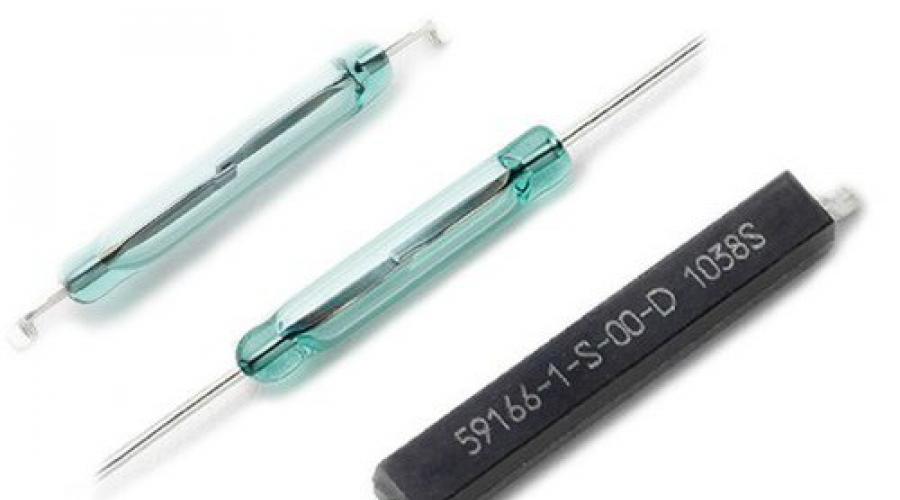
It is in the principle of constructing the sensor that its high reliability is based. It uses the interaction of a sealed magnetically controlled contact (abbreviated as a reed switch), which serves as an actuator, and a magnet, which serves as a control element.

The actuator (reed switch) has a very simple design: it immediately combines contact and magnetic systems, which are hermetically sealed in a glass container. This design of the reed switch made it possible to obtain characteristics superior to known contacts: speed, stable parameters, high wear resistance and reliability.
The contacts are made of soft magnetic material, they are separated by a gap of only 300-500 microns, which has certain disadvantages: increased sparking and increased contact resistance. This leads to sudden “sticking” of contacts and failure of the detector.
Since there are no intermediate links in the detector reed switch, and the contacts switch small electricity, then the actuator has almost zero wear. This is also facilitated by the fact that the cylinder contains nitrogen under high pressure, which eliminates contact oxidation.
The control (setting) element can be made in several versions: or magnetic circuit.
Classification of magnetic contact detectors
Detectors, like any other equipment, are subject to standardization, and this task is solved by the international standard IEC 62642-2-6. Its requirements apply to magnetic contact detectors, intended for blocking doors, hatches, windows, containers.
This standard introduces four risk classes for these sensors: 1 - low risk, 2 - risk intermediate between classes 1 and 3, 3 - medium risk, 4 - high risk.
The above classification determines the critical and non-critical parameters of the detector for each class. For example, response and recovery distances, protection against damage to the alarm loop and complete loss of supply voltage should be mandatory parameters for all four classes.
IN Russian Federation detectors of class 1 or 2 are used international standard IEC 62642-2-6, that is, they do not require indication of detection of damage to the protected structure, protection from foreign magnetic influence, or low supply voltage.
Requirements for the functionality of magnetic contact detectors
Magnetic contact detectors must meet certain requirements for their functionality, namely:
- the triggering distance excludes an attempt by an attacker to penetrate a controlled structure or move a protected item, as well as replace parts of the detector without sending an alarm signal;
- recovery distance must exclude false alarm detector. - relative displacement of the detector blocks (alignment) should not lead to the cessation of its operation;
The functionality of magnetic contact detectors depends on the type of sensor, its size, installation location, and the material of the protected structure.
Sensor markings
The magnetic contact sensor has a standardized name - security point magnetic contact detector IO. This is followed by a digital code characterizing the detection zones and the operating principle of the detector.

For example, a magnetic contact detector IO 102 (SMK) is marked IO 102, indicating that this equipment belongs to the type of detectors (letter I) and is used in security systems ah (letter O), has a point detection zone (number 1) and a magnetic contact operating principle (numbers 0 and 2).
Detector selection
The choice of equipment such as a magnetic contact security detector IO is important step. First of all, it must correspond to the installation location, the material of the protected structure, the conditions of detention, as well as your requirements.
If it is necessary to protect a separate object, then this task will be performed by the security magnetic contact detector IO 102-2 (push-button).
IO 102-20/A2 is perfect for blocking doors, windows and other room elements. He is also able to protect himself from sabotage ("trap"). That is, the noise immunity of the sensor is an important aspect in matters of its selection.
The conditions under which the detector is kept must also be taken into account, and if the environment is explosive, then the IO 102-26/V sensor is suitable for it.

The sensor is designed for air temperatures from minus 40 to plus 50 degrees Celsius.

Attention is also drawn to the characteristics of the reed switch: they must meet your conditions.
Installation of detector blocks
The magnetic contact point detector and the alarm loop are attached to the surface of the protected structure from the side of the room. The control element is mounted, as a rule, on a moving part of the structure (door, window, cover), and the control unit with an alarm loop is mounted on a stationary part ( doorjamb, frame, body).

The method of attaching the detector depends on the surface on which it is mounted: on wood - with screws, on metal - with screws, on glass - with “Contact” glue. Between the detector blocks and mounting surface A dielectric gasket must be installed.

The installation method described applies to open type, but in some cases there is a need for hidden installation sensor This is what detectors are for. cylindrical. The very shape of the sensor allows it to be installed hidden from prying eyes and not disturb the interior of the room. But this type of installation has a certain drawback: it is fundamentally important to maintain the alignment of the ends of the actuating and control elements of the detector (within 2-3 mm).
Sabotage of sensors and how to deal with it
According to amateurs, magnetic contact detectors are easily bypassed, that is, ignored. And this is done, in their opinion, with the help of external strong magnet.
In reality, this is far from the case, especially when it comes to In this case, sabotage of the sensors is practically impossible, since the steel will close the action of the external magnet and it will not reach the actuator.
In cases with a non-metallic structure, everything is also not simple: a certain orientation of the external magnet is required, otherwise its effect on the actuator can cause the reed switch to open and trigger the alarm.
If these arguments are unconvincing, then there are simple ways protection against sabotage of detectors:
- the use of two sets of magnetic contact sensors with multidirectional magnets located about 15 mm from each other and connected in series;
- the use of an additional screen in the form of a steel plate with a thickness of 0.5 mm or more;
Briefly about the disadvantages
Magnetic contact detector SMK has individual features actuator, limiting its use:
- dependence of contact pressing on the magnet strength of the control element and control current;
- dependence of the switching capacity on the volume of the reed switch cylinder;
the length of the contacts contributes to their significant rattling during vibration and shock;
Conclusion
The IO magnetic contact detector is deservedly considered the simplest and most reliable means of protecting objects and structures from intruders. A significant advantage of the sensor is its low cost. Security systems containing this type of detector are often preferred. Today there are many security systems created according to innovative technologies, but magnetic contact detectors remain in demand to this day.
Fire detector— a device for generating a fire signal. Using the term "sensor" is a misnomer because the sensor is part of the detector. Despite this, the term "sensor" is used in many industry regulations to mean "detector".
Legend
The symbol for fire detectors must consist of the following elements: IP Х1Х2Х3-Х4-Х5.
The abbreviation IP defines the name “fire detector”. Element X1 - indicates a controlled sign of fire; Instead of X1, one of the following digital designations is given:
1 - thermal;
2 - smoke;
3 - flame;
4 - gas;
5 - manual;
6...8 - reserve;
9 - when monitoring other signs of fire.
Element X2X3 denotes the operating principle of the PI; instead of Х2Х3 one of the following digital designations is given:
01 - using dependency electrical resistance elements from temperature;
02 - using thermo-EMF;
03 - using linear expansion;
04 - using fusible or combustible inserts;
05 - using the dependence of magnetic induction on temperature;
06 - using the Hall effect;
07 - using volumetric expansion (liquid, gas);
08 - using ferroelectrics;
09 - using the dependence of the elastic modulus on temperature;
10 - using resonant-acoustic methods of temperature control;
11 - radioisotope;
12 - optical;
13 - electrical induction;
14 - using the “shape memory” effect;
15...28 - reserve;
29 - ultraviolet;
30 - infrared;
31 — thermobarometric;
32 - using materials that change optical conductivity depending on temperature;
33 - aeroionic;
34 - thermal noise;
35 - when using other principles of action.
Element X4 indicates the serial number of development of a detector of this type.
Element X5 indicates the class of the detector.
Classification based on restartability
Automatic fire detectors, depending on the possibility of their reactivation after activation, are divided into the following types:
- returnable detectors with the possibility of reactivation - detectors that, from the state fire alarm can return to the control state without replacing any nodes, if only the factors that led to their operation have disappeared. They are divided into types:
- detectors with automatic reactivation - detectors that, after being triggered, independently switch to the monitoring state;
- detectors with remote reactivation - detectors that, using a remote command, can be transferred to the monitoring state;
- manually activated detectors are detectors that, using manual switching on the detector itself can be switched to the control state;
- detectors with replaceable elements - detectors that, after being triggered, can be transferred to the control state only by replacing some elements;
- detectors without the possibility of reactivation (without replaceable elements) - detectors that, after being triggered, can no longer be transferred to the monitoring state.
Classification by type of signal transmission
Automatic fire detectors are divided according to the type of signal transmission:
- dual-mode detectors with one output for transmitting a signal both about the absence and presence of signs of fire;
- multi-mode detectors with one output for transmitting a limited number (more than two) types of signals about a state of rest, fire alarm or other possible conditions;
- analogue detectors, which are designed to transmit a signal about the value of the fire sign controlled by them, or an analogue/digital signal, and which is not a direct fire alarm signal.

Application
Heat fire detector designed in the 19th century. Consists of two wires a and b, which are connected to each other by washers cc made of a material that does not conduct electricity. On the side of the device there is a tube d with a capsule e filled with mercury and closed from below with a wax plate. When the temperature rises, the wax melts, mercury is poured into the device and contact is established between the two wires, as a result of which a signal appears
Apply if initial stages A fire generates a significant amount of heat, for example in fuel and lubricant warehouses. Or in cases where the use of other detectors is impossible. Use in administrative and domestic premises is prohibited.
The highest temperature field is located at a distance of 10...23 cm from the ceiling. Therefore, it is in this area that it is desirable to place the heat-sensitive element of the detector. A heat detector located under the ceiling at a height of six meters above the fire will be triggered when the heat generated by the fire is 420 kW.
Spot
A detector that responds to fire factors in a compact area.
Multipoint
Heat multipoint detectors are automatic detectors, the sensitive elements of which are a set of point sensors discretely located along the line. The step of their installation is determined by the requirements regulatory documents and technical characteristics specified in technical documentation for a specific product.
Linear (thermal cable)
There are several types of linear thermal fire detectors, structurally different from each other:
- semiconductor - a linear thermal fire detector in which the wires are coated with a substance having a negative temperature coefficient as a temperature sensor. This type of thermal cable only works in conjunction with an electronic control unit. When any section of the thermal cable is exposed to temperature, the resistance at the point of exposure changes. Using the control unit, you can set different temperature response thresholds;
- mechanical - a sealed metal tube filled with gas is used as a temperature sensor for this detector, as well as a pressure sensor connected to an electronic control unit. When exposed to temperature, any part of the sensor tube changes internal pressure gas, the value of which is recorded by the electronic unit. This type reusable linear thermal fire detector. The length of the working part of the metal tube of the sensor is limited in length to 300 meters;
- electromechanical - linear heat fire detector, which uses a heat-sensitive material applied to two mechanically stressed wires as a temperature sensor ( twisted pair), Under the influence of temperature, the heat-sensitive layer softens and the two conductors are short-circuited.

Smoke detectors are detectors that react to combustion products that can affect the absorption or scattering ability of radiation in the infrared, ultraviolet or visible ranges of the spectrum. Smoke detectors can be point, linear, aspirating and autonomous.
Application
The symptom that smoke detectors respond to is smoke. The most common type of detector. When protected by the system fire alarm In administrative and amenity premises, only smoke detectors should be used. The use of other types of detectors in administrative and utility premises is prohibited. The number of detectors protecting a room depends on the size of the room, the type of detector, the presence of systems (fire extinguishing, smoke removal, equipment blocking) controlled by the fire alarm system.
Up to 70% of fires arise from thermal microfoci that develop in conditions with insufficient access to oxygen. This development of the fire, accompanied by the release of combustion products and occurring over several hours, is typical for cellulose-containing materials. It is most effective to detect such fires by recording combustion products in small concentrations. Smoke or gas detectors can do this.
Optical
Smoke detectors using optical detection react differently to smoke different colors. Manufacturers currently provide limited information about smoke detector response in technical specifications. Detector response information only includes nominal response (sensitivity) values for gray smoke, not black. Often a range of sensitivity is given instead of an exact value.
Spot
Triggered smoke detector (red LED lit continuously)
Smoke detectors must be closed during repairs in the room to prevent dust from entering.
A point detector responds to fire factors in a compact area. The operating principle of point optical detectors is based on the scattering of infrared radiation by gray smoke. They respond well to gray smoke released during smoldering in the early stages of a fire. Reacts poorly to black smoke, which absorbs infrared radiation.
For periodic maintenance of detectors it is necessary plug connection, the so-called “socket” with four contacts into which the smoke detector is connected. To control the disconnection of the sensor from the loop, there are two negative contacts, which close when the detector is installed in a socket.
Smoke chamber and point smoke detector electronics
All IP 212-XX point smoke optical fire detectors according to the NPB 76-98 classification use the effect of diffuse scattering of LED radiation on smoke particles. The LED is positioned in such a way as to exclude direct hit its radiation to the photodiode. When smoke particles appear, part of the radiation is reflected from them and hits the photodiode. To protect from external light, an optocoupler - an LED and a photodiode are placed in a smoke chamber made of black plastic.
Experimental studies have shown that the time to detect a test fire when smoke detectors are located at a distance of 0.3 m from the ceiling increases by 2..5 times. And when installing a detector at a distance of 1 m from the ceiling, it is possible to predict an increase in the time of fire detection by 10..15 times.
When the first Soviet optical smoke detectors were developed, there was no specialized element base, standard LEDs and photodiodes. In the IDF-1M photoelectric smoke detector, an SG24-1.2 type incandescent lamp and an FSK-G1 type photoresistor were used as an optocoupler. This determined the low specifications detector IDF-1M and poor protection from external influences: response inertia at an optical density of 15 - 20%/m was 30 s, supply voltage 27±0.5 V, current consumption more than 50 mA, weight 0.6 kg, background illumination up to 500 lux, speed air flow up to 6 m/s.
The combined smoke and heat detector DIP-1 used an LED and a photodiode, located in a vertical plane. It was no longer continuous radiation that was used, but pulsed radiation: duration 30 μs, frequency 300 Hz. To protect against interference, synchronous detection was used, i.e. the amplifier input was open only while the LED was emitting. This provided higher protection against interference than in the IDF-1M detector and significantly improved the characteristics of the detector: inertia decreased to 5 s at an optical density of 10%/m, i.e. 2 times smaller, the weight decreased by 2 times, the permissible background illumination increased 20 times, up to 10,000 lux, the permissible air flow speed increased to 10 m/s. In the "Fire" mode, the red LED indicator turned on. To transmit an alarm signal in the DIP-1 and IDF-1M detectors, a relay was used, which determined significant current consumption: more than 40 mA in standby mode and more than 80 mA in alarm, with a supply voltage of 24 ± 2.4 V and the need to use separate signal circuits and power circuits. The maximum time between failures of DIP-1 is 1.31·104 hours.
Linear detectors

Linear - a two-component detector consisting of a receiver block and an emitter block (or one receiver-emitter and reflector block) reacts to the appearance of smoke between the receiver and emitter blocks.
The design of linear smoke fire detectors is based on the principle of attenuation electromagnetic flux between a radiation source and a photodetector spaced apart in space under the influence of smoke particles. A device of this type consists of two blocks, one of which contains a source of optical radiation, and the other a photodetector. Both blocks are located on the same geometric axis in the line of sight.
A special feature of all linear smoke detectors is the self-test function with transmission of the “Fault” signal to the control panel. Because of this feature, simultaneously with other detectors, it is correct to use it only in alternating loops. Inclusion linear detectors into constant-sign loops leads to blocking of the “Fire” signal by the “Fault” signal, which contradicts the Air Safety Regulations 75. Only one linear detector can be included in a constant-sign loop.
One of the first Soviet linear detectors was called DOP-1 and used an SG-24-1.2 incandescent lamp as a light source. A germanium photodiode was used as a photodetector. The detector consisted of a receiving and transmitting unit, which serves to emit and receive a light beam, and a light reflector, installed perpendicular to the directed light beam at the required distance. The nominal distance between the receiving and transmitting unit and the reflector is 2.5±0.1 m.
The Soviet-made photobeam device FEUP-M consisted of an infrared beam emitter and photodetector.
Aspirating detectors

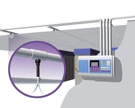
The aspiration detector uses forced air extraction from the protected volume with monitoring by ultra-sensitive laser smoke detectors and ensures ultra-early detection of a critical situation. Aspirating smoke detectors allow you to protect objects in which it is impossible to directly place a fire detector.
The fire aspiration detector is applicable in archives, museums, warehouses, server rooms, switching rooms of electronic communication centers, control centers, “clean” production areas, hospital rooms with high-tech diagnostic equipment, television centers and broadcasting stations, computer rooms and other rooms with expensive equipment . That is, for the most important premises where they are stored material values or where the investment in equipment is enormous, or where the damage from stopping production or interruption of operation is great, or the lost profit from the loss of information is great. At such facilities, it is extremely important to reliably detect and eliminate the source at the very early stage development, at the smoldering stage - long before the appearance of open fire, or when overheating of individual components occurs electronic device. At the same time, taking into account that such zones are usually equipped with a temperature and humidity control system, and air filtration is performed in them, it is possible to significantly increase the sensitivity of the fire detector, while avoiding false alarms.
Disadvantage aspiration detectors is their high cost.
Autonomous detectors
Autonomous - a fire detector that responds to a certain level of concentration of aerosol combustion products (pyrolysis) of substances and materials and, possibly, other fire factors, in the housing of which it is structurally combined standalone source power supply and all components necessary to detect a fire and immediately notify about it. The autonomous detector is also a point detector.
Ionization detectors

The principle of operation of ionization detectors is based on recording changes in the ionization current that arise as a result of exposure to combustion products. Ionization detectors are divided into radioisotope and electrical induction.
Radioisotope detectors

A radioisotope detector is a smoke fire detector that is triggered by exposure to combustion products. ionization current internal working chamber of the detector. The operating principle of a radioisotope detector is based on the ionization of the air in the chamber when it is irradiated with a radioactive substance. When oppositely charged electrodes are introduced into such a chamber, an ionization current occurs. Charged particles “stick” to heavier smoke particles, reducing their mobility - the ionization current decreases. Its decrease to a certain value is perceived by the detector as an “alarm” signal. Such a detector is effective in smoke of any nature. However, along with the advantages described above, radioisotope detectors have significant drawback which should not be forgotten. It's about on the use of a radioactive radiation source in the design of detectors. In this regard, problems arise in observing safety measures during operation, storage and transportation, as well as disposal of detectors after the end of their service life. Effective for detecting fires accompanied by the appearance of so-called “black” types of smoke, characterized by high level absorption of light.
In Soviet radioisotope detectors (RID-1, KI), the source of ionization was the radioactive isotope of plutonium-239. Detectors are included in the first group of potential radiation hazards.
Radioisotope smoke detector RID-1
The main element of the RID-1 radioisotope detector is two ionization chambers connected in series. The connection point is connected to the control electrode of the thyratron. One of the chambers is open, the other is closed and acts as a compensating element. Ionization of the air in both chambers is created by an isotope of plutonium. Under the influence of applied voltage, an ionization current flows in the chambers. If smoke gets into open camera its conductivity decreases, the voltage on both chambers is redistributed, resulting in a voltage on the control electrode of the thyratron. When the ignition voltage is reached, the thyratron begins to conduct current. An increase in current consumption triggers an alarm. Radiation sources built into the detector do not pose a danger, since the radiation is completely absorbed by the ionization chambers. Danger can only arise if the integrity of the radiation source is compromised. The detector also uses a TH11G thyratron with a small amount of radioactive nickel; the radiation is absorbed by the volume of the thyratron and its walls. Danger may arise if the thyratron breaks.
The designated service life of the radioactive sources of the detectors was:
RID-1; KI-1; DI-1 - 6 years;
RID-6; RID-6m and similar - 10 years.
The radioisotope smoke fire detector of the RID-6M type has been mass-produced for more than 15 years at the Signal plant (Obninsk, Kaluga region) with a total production volume of up to 100 thousand units. in year. The RID-6M detector has a limited designated service life for alpha sources of the AIP-RID type - 10 years from the date of their release. There is a technology for installing new alpha sources of the AIP-RID type in fire detectors of previous years of production, which allows the continued operation of the detectors for another 10 years, instead of their forced dismantling and burial.
High sensitivity allows the use of radioisotope detectors as compound component aspiration detectors. When pumping air from the protected premises through the detector, it can provide a signal when even an insignificant amount of smoke appears - from 0.1 mg/m³. In this case, the length of the air intake tubes is practically unlimited. For example, it almost always registers the fact of ignition of a match head at the input air intake tube 100 m long.
Electroinduction detectors

The operating principle of the detector: aerosol particles are sucked from the environment into a cylindrical tube (gas duct) using a small-sized electric pump and fall into the charging chamber. Here, under the influence of a unipolar corona discharge, the particles acquire a volumetric electric charge and, moving further along the gas duct, they enter the measuring chamber, where they induce an electrical signal on its measuring electrode, proportional to the space charge of the particles and, consequently, their concentration. The signal from the measuring chamber enters the pre-amplifier and then into the signal processing and comparison unit. The sensor selects the signal by speed, amplitude and duration and provides information when specified thresholds are exceeded in the form of closing a contact relay.
Electrical induction detectors are used in the fire alarm systems of the Zarya and Pirs modules of the ISS.
Flame detectors

Flame detector - a detector that responds to electromagnetic radiation flame or smoldering hearth.
Flame detectors are used, as a rule, to protect areas where it is necessary high efficiency detection, since fire detection by flame detectors occurs in the initial phase of the fire, when the temperature in the room is still far from the values at which thermal fire detectors are triggered. Flame detectors provide the ability to protect areas with significant heat exchange and open areas where the use of heat and smoke detectors is not possible. Flame detectors are used to monitor the presence of overheated surfaces of units during accidents, for example, to detect a fire in the car interior, under the skin of the unit, to monitor the presence of solid fragments of overheated fuel on the conveyor.
Gas detectors

Gas detector - a detector that responds to gases released during smoldering or burning of materials. Gas detectors can react to carbon monoxide (carbon dioxide or carbon monoxide), hydrocarbon compounds.
Flow-through fire detectors
Flow fire detectors are used to detect fire factors as a result of analyzing the environment spreading through ventilation ducts exhaust ventilation. Detectors should be installed in accordance with the operating instructions for these detectors and the manufacturer’s recommendations, agreed upon with authorized organizations (those with permission for the type of activity).
Manual call points

Fire manual call point is a device designed to manually activate a fire alarm signal in fire alarm and fire extinguishing systems. Manual fire call points should be installed at a height of 1.5 m from the ground or floor level. The illumination at the installation site of the manual fire call point must be at least 50 Lux.
Manual fire call points must be installed on escape routes in places accessible for their activation in the event of a fire.
In structures for above-ground storage of flammable and combustible liquids, manual call points are installed on the embankment.
By 1900, 675 manual call points were installed in London with signal output to the fire service. By 1936 the number had increased to 1,732.
In 1925, in Leningrad there were manual call points in 565 points; in 1924, they transmitted about 13% of all fire reports in the city. At the beginning of the 20th century, there were manual call points that were included in the ring loop of the recording device. When turned on, the detector produced an individual number of short circuits and open circuits and thus transmitted a signal to the Morse apparatus installed on the recording device. Manual call points designs of that time consisted of a clock mechanism with a pendulum escapement, consisting of two main gears and a signal wheel with three rubbing contacts. The mechanism is actuated by a coil spring, and the detector mechanism, when actuated, repeats the signal number four times. One spring winding is enough to send six signals. The contact parts of the mechanism are coated with silver to avoid oxidation. This type of alarm was proposed in 1924 by the Head of the Fire Telegraph Workshops A.F. Ryulman, whose devices were installed for experimental purposes in 7 points of the Central part of the city with a receiving station in the part named after. Comrade Lenin. The operation of the alarm system was opened on March 6, 1924. After ten months of trial operation, which showed that there was no case of non-reception of a signal and that the alarm operation showed complete trouble-free and accurate operation, the system was recommended for widespread use.
Application in hazardous areas
When protecting explosive objects with fire alarm systems, it is necessary to use detectors with explosion protection means. For point smoke detectors, the explosion protection type “intrinsically safe” is used. electrical circuit(i)". For thermal, manual, gas and flame detectors, the explosion protection types “intrinsically safe electrical circuit (i)” or “flameproof enclosure (d)” are used. A combination of protections i and d is also possible in one detector.