Heat supply system control system. Industry analytical heat supply management system ACS “Heat. Information aspect of constructing an automated process control system for heat supply
Read also
An important public service in modern cities is heat supply. The heat supply system serves to meet the needs of the population for heating services in residential and public buildings, hot water supply (water heating) and ventilation.
A modern urban heat supply system includes the following main elements: a heat source, heat transfer networks and devices, as well as heat-consuming equipment and devices - heating, ventilation and hot water supply systems.
Urban heat supply systems are classified according to the following criteria:
- - degree of centralization;
- - type of coolant;
- - method of generating thermal energy;
- - method of supplying water for hot water supply and heating;
- - number of heating network pipelines;
- - a method of providing consumers with thermal energy, etc.
By degree of centralization heating supplies are distinguished two main types:
- 1) centralized heat supply systems, which have been developed in cities and areas with predominantly multi-story buildings. Among them we can highlight: highly organized centralized heat supply based on the combined production of heat and electricity at thermal power plants - district heating and centralized heat supply from district heating and industrial heating boiler houses;
- 2) decentralized heat supply from small house boiler installations (attached, basement, roof), individual heating devices, etc.; At the same time, there are no heating networks and associated thermal energy losses.
By type of coolant There are steam and water heat supply systems. In steam heating systems, superheated steam acts as a coolant. These systems are used mainly for technological purposes in industry and power generation. Due to the increased danger during their operation, they are practically not used for the needs of municipal heat supply to the population.
In water heating systems, the coolant is hot water. These systems are used mainly to supply thermal energy to urban consumers, for hot water supply and heating, and in some cases for technological processes. In our country, water heating systems make up more than half of all heating networks.
By method of generating thermal energy distinguish:
- - combined heat and electricity generation at thermal power plants. In this case, the heat of the working thermal water steam is used to generate electricity when the steam expands in turbines, and then the remaining heat of the exhaust steam is used to heat water in the heat exchangers that make up the heating equipment of the CHP plant. Hot water is used to supply heat to urban consumers. Thus, at a thermal power plant, heat of high potential is used to generate electricity, and heat of low potential is used for heat supply. This is the energetic meaning of combined heat and electricity generation, which ensures a significant reduction in specific fuel consumption when generating thermal and electrical energy;
- - separate generation of thermal energy, when heating of water in boiler plants (thermal stations) is separated from the generation of electrical energy.
By water supply method For hot water supply, water heating systems are divided into open and closed. In open water heating systems, hot water is supplied to the water taps of the local hot water supply system directly from the heating networks. In closed water heating systems, water from heating networks is used only as a heating medium for heating tap water in water heaters - heat exchangers (boilers), which then enters the local hot water supply system.
By number of pipelines There are one-pipe, two-pipe and multi-pipe heat supply systems.
By way to provide consumers thermal energy differs between single-stage and multi-stage heat supply systems - depending on the schemes for connecting subscribers (consumers) to heating networks. The nodes for connecting heat consumers to heating networks are called subscriber inputs. At the subscriber input of each building, hot water heaters, elevators, pumps, fittings, and instrumentation are installed to regulate the parameters and flow of coolant for local heating and water distribution devices. Therefore, the subscriber input is often called a local heating point (MTP). If a subscriber input is constructed for a separate facility, then it is called an individual heating point (IHP).
When organizing single-stage heat supply systems, heat consumers are connected directly to heating networks. Such direct connection of heating devices limits the permissible pressure limits in heating networks, since the high pressure required to transport the coolant to end users is dangerous for heating radiators. Because of this, single-stage systems are used to supply heat to a limited number of consumers from boiler houses with a short heating network length.
In multi-stage systems, central heating (CHP) or control and distribution points (CDP) are placed between the heat source and consumers, in which the coolant parameters can be changed at the request of local consumers. Central heating and distribution centers are equipped with pumping and water heating units, control and safety valves, and instrumentation designed to provide a group of consumers in a block or region with thermal energy of the required parameters. With the help of pumping or water heating units, main pipelines (first stage) are partially or completely hydraulically isolated from distribution networks (second stage). From the central heating point or distribution point, coolant with acceptable or established parameters is supplied through common or separate pipelines of the second stage to the MTP of each building for local consumers. At the same time, only elevator mixing of return water from local heating installations, local regulation of water flow for hot water supply and heat consumption metering are carried out in the MTP.
The organization of complete hydraulic insulation of heating networks of the first and second stages is the most important measure to increase the reliability of heat supply and increase the distance of heat transport. Multi-stage heat supply systems with central heating stations and heat exchangers make it possible to reduce by tens of times the number of local hot water heaters, circulation pumps and temperature controllers installed in the MTP with a single-stage system. In the central heating station it is possible to organize the treatment of local tap water to prevent corrosion of hot water supply systems. Finally, when constructing a central heating substation and a distribution center, the unit operating costs and the cost of maintaining personnel to service equipment in the MTP are significantly reduced.
Thermal energy in the form of hot water or steam is transported from a thermal power plant or boiler house to consumers (residential buildings, public buildings and industrial enterprises) through special pipelines - heating networks. The route of heating networks in cities and other populated areas should be provided in the technical lanes reserved for engineering networks.
Modern heating networks of urban systems are complex engineering structures. Their length from source to consumers is tens of kilometers, and the diameter of the mains reaches 1400 mm. Heat networks include heat pipelines; compensators that perceive temperature extensions; shutdown, control and safety equipment installed in special chambers or pavilions; pumping stations; regional heating points (RTP) and heating points (TP).
Heating networks are divided into main lines, laid in the main directions of a settlement, distribution networks - within a block, microdistrict - and branches to individual buildings and subscribers.
Heat network diagrams are usually used as radial ones. To avoid interruptions in the heat supply to the consumer, it is necessary to connect individual main networks to each other, as well as install jumpers between branches. In large cities, if there are several large heat sources, more complex heating networks are built in a ring pattern.
To ensure reliable functioning of such systems, it is necessary to construct them hierarchically, in which the entire system is divided into a number of levels, each of which has its own task, decreasing in importance from the top level to the bottom. The upper hierarchical level consists of heat sources, the next level - main heating networks with RTP, the lower - distribution networks with consumer inputs. Heat sources supply hot water of a given temperature and a given pressure to heating networks, ensure the circulation of water in the system and maintain the proper hydrodynamic and static pressure in it. They have special water treatment plants where chemical purification and deaeration of water are carried out. The main heat carrier flows are transported through the main heating networks to the heat consumption units. In the RTP, the coolant is distributed among the regions, and autonomous hydraulic and thermal regimes are maintained in the district networks. The organization of a hierarchical structure of heat supply systems ensures their controllability during operation.
To control the hydraulic and thermal modes of the heat supply system, it is automated, and the amount of supplied heat is regulated in accordance with consumption standards and the requirements of subscribers. The largest amount of heat is spent on heating buildings. The heating load changes with the outside temperature. To keep the heat supply consistent with consumers, it uses central regulation at the heat sources. It is not possible to achieve high quality heat supply using only central regulation, therefore additional automatic regulation is used at heating points and at consumers. The water consumption for hot water supply is constantly changing, and in order to maintain a stable heat supply, the hydraulic mode of the heating networks is automatically adjusted, and the temperature of the hot water is maintained constant and equal to 65 ° C.
The main systemic problems that complicate the organization of an effective mechanism for the functioning of heat supply in modern cities include the following:
- - significant physical and moral wear and tear of heat supply system equipment;
- - high level of losses in heating networks;
- - a massive lack of heat metering devices and heat supply regulators among residents;
- - overestimated heat loads among consumers;
- - imperfection of the regulatory and legislative framework.
The equipment of thermal power engineering enterprises and heating networks has a high degree of wear on average in Russia, reaching 70%. The total number of heating boiler houses is dominated by small, inefficient ones; the process of their reconstruction and liquidation proceeds very slowly. The increase in thermal capacity annually lags behind the increasing loads by 2 times or more. Due to systematic interruptions in the supply of boiler fuel in many cities, serious difficulties arise annually in the heat supply of residential areas and houses. The start-up of heating systems in the fall lasts for several months, “under-heating” of residential premises in the winter has become the norm, not the exception; The rate of equipment replacement is decreasing, and the amount of equipment in disrepair is increasing. This has predetermined a sharp increase in the accident rate of heat supply systems in recent years.
Siemens is a recognized world leader in the development of energy systems, including heat and water supply systems. This is exactly what one of the Departments does Siemens - Building Technologies – “Automation and safety of buildings.” The company offers a full range of equipment and algorithms for the automation of boiler houses, heating points and pumping stations.
1. Structure of the heat supply system
Siemens offers a comprehensive solution for creating a unified management system for urban heat and water supply systems. The complexity of the approach lies in the fact that customers are offered everything from performing hydraulic calculations of heat and water supply systems to communication and dispatch systems. The implementation of this approach is ensured by the accumulated experience of the company’s specialists, acquired in different countries of the world during the implementation of various projects in the field of heat supply systems in large cities in Central and Eastern Europe. This article discusses the structures of heat supply systems, principles and control algorithms that were implemented during the implementation of these projects.
Heat supply systems are built primarily according to a 3-stage scheme, the parts of which are:
1. Heat sources of different types, interconnected into a single loop system
2. Central heating points (CHS), connected to main heating networks with high coolant temperatures (130...150°C). In the central heating substation, the temperature gradually decreases to a maximum temperature of 110 °C, based on the needs of the heating substation. In small systems, the level of central heating points may be absent.
3. Individual heating points that receive thermal energy from central heating stations and provide heat supply to the facility.
The fundamental feature of Siemens solutions is that the entire system is based on the principle of 2-pipe wiring, which is the best technical and economic compromise. This solution makes it possible to reduce heat losses and electricity consumption in comparison with the 4-pipe or 1-pipe systems with open water intake that are widespread in Russia, investments in the modernization of which without changing their structure are not effective. The costs of maintaining such systems are constantly increasing. Meanwhile, it is the economic effect that is the main criterion for the feasibility of development and technical improvement of the system. It is obvious that when constructing new systems, optimal solutions tested in practice should be taken. If we are talking about a major overhaul of a heat supply system with a suboptimal structure, it is economically profitable to switch to a 2-pipe system with individual heating points in each house.
When providing consumers with heat and hot water, the management company incurs fixed costs, the structure of which is as follows:
Costs of generating heat for consumption;
losses in heat sources due to imperfect heat generation methods;
heat losses in heating mains;
R electricity costs.
Each of these components can be reduced with optimal management and the use of modern automation tools at each level.
2. Heat sources
It is known that for heating systems, large sources of combined heat and power generation or sources in which heat is a secondary product, for example, a product of industrial processes, are preferable. It was on the basis of such principles that the idea of central heating arose. Boiler houses operating on different types of fuel, gas turbines, etc. are used as backup heat sources. If gas boiler houses serve as the main source of heat, they must operate with automatic optimization of the combustion process. This is the only way to achieve savings and reduce emissions compared to distributed heat generation in each house.
3. Pumping stations
Heat from heat sources is transferred to main heating networks. The coolant is pumped by network pumps that operate continuously. Therefore, special attention should be paid to the selection and method of operating pumps. The operating mode of the pump depends on the modes of the heating points. A decrease in flow at the central heating station entails an undesirable increase in the pressure of the pump (pumps). An increase in pressure negatively affects all components of the system. At best, only hydraulic noise increases. In any case, electrical energy is lost. Under these conditions, an unconditional economic effect is ensured by frequency control of pumps. Various control algorithms are used. In the basic design, the controller maintains a constant pressure drop across the pump by varying the rotation speed. Due to the fact that with a decrease in coolant flow, pressure losses in the lines are reduced (quadratic dependence), it is also possible to reduce the set value (set) of the pressure drop. This type of pump control is called proportional and can further reduce pump operating costs. More efficient control of pumps with task correction based on a “remote point”. In this case, the pressure drop at the end points of the main networks is measured. The current differential pressure values compensate for the pressure at the pumping station.
4. Central heating points (CHS)
In modern heat supply systems, central heating stations play a very important role. An energy-saving heat supply system should operate using individual heating points. However, this does not mean that central heating stations will be closed: they act as a hydraulic stabilizer and at the same time divide the heat supply system into separate subsystems. In the case of using IHP, central hot water supply systems are excluded from the central heating point. In this case, only 2 pipes pass through the central heating substation, separated by a heat exchanger, which separates the system of main routes from the ITP system. Thus, the ITP system can operate with other coolant temperatures, as well as with lower dynamic pressures. This guarantees stable operation of the ITP and at the same time entails a reduction in investment in ITP. The supply temperature from the central heating point is adjusted in accordance with the temperature schedule based on the outside air temperature, taking into account the summer limit, which depends on the demand of the domestic hot water system in the heating and heating system. We are talking about preliminary adjustment of coolant parameters, which allows reducing heat losses in secondary routes, as well as increasing the service life of thermal automation components in ITP.
5. Individual heating points (IHP)
The operation of the IHP affects the efficiency of the entire heat supply system. ITP is a strategically important part of the heat supply system. The transition from a 4-pipe system to a modern 2-pipe system is not without its challenges. Firstly, this entails the need for investment, and secondly, without the presence of a certain “know-how”, the introduction of ITP can, on the contrary, increase the operating costs of the management company. The principle of operation of the ITP is that the heating point is located directly in the building, which is heated and for which hot water is prepared. At the same time, only 3 pipes are connected to the building: 2 for coolant and 1 for cold water supply. Thus, the structure of the system pipelines is simplified, and during planned repairs of routes, savings on pipe laying immediately occur.
5.1. Heating circuit control
The ITP controller controls the thermal power of the heating system, changing the temperature of the coolant. The heating temperature setpoint is determined by the outside temperature and the heating curve (weather-compensated control). The heating curve is determined taking into account the inertia of the building.
5.2. Inertia of the building
The inertia of buildings has a significant influence on the outcome of weather-compensated heating control. A modern ITP controller must take this influencing factor into account. The inertia of a building is determined by the value of the building's time constant, which ranges from 10 hours for panel houses to 35 hours for brick houses. The ITP controller determines, based on the building time constant, the so-called “combined” outdoor air temperature, which is used as a correction signal in the automatic heating water temperature control system.
5.3. Wind power
Wind significantly affects the room temperature, especially in high-rise buildings located in open areas. An algorithm for correcting water temperature for heating, taking into account the influence of wind, provides up to 10% savings in thermal energy.
5.4 Return water temperature limitation
All types of control described above indirectly affect the reduction of return water temperature. This temperature is the main indicator of the economical operation of the heating system. Under various operating modes of the IHP, the return water temperature can be reduced using limiting functions. However, all restriction functions entail deviations from comfortable conditions, and their use must have a feasibility study. In independent heating circuit connection schemes, with economical operation of the heat exchanger, the temperature difference between the return water of the primary circuit and the heating circuit should not exceed 5°C. Cost-effectiveness is ensured by the function of dynamic limitation of return water temperature ( DRT – differential of return temperature ): when the specified temperature difference between the return water of the primary circuit and the heating circuit is exceeded, the controller reduces the coolant flow in the primary circuit. At the same time, the peak load also decreases (Fig. 1).
The article is devoted to the use of the Trace Mode SCADA system for online and remote control of city centralized heating facilities. The facility where the described project was implemented is located in the south of the Arkhangelsk region (the city of Velsk). The project provides for operational monitoring and management of the process of preparing and distributing heat for heating and supplying hot water to city vital facilities.
CJSC "SpetsTeploStroy", Yaroslavl
Statement of the problem and necessary functions of the system
The goal that our company faced was to build a backbone network for heat supply to most of the city, using advanced construction methods, where pre-insulated pipes were used to construct the network. For this purpose, fifteen kilometers of main heating networks and seven central heating points (CHS) were built. The purpose of the central heating station is to use superheated water from the GT-CHP (according to the schedule 130/70 °C), prepare the coolant for intra-block heating networks (according to the schedule 95/70 °C) and heat the water to 60 °C for the needs of domestic hot water supply (hot water supply), The central heating station operates according to an independent, closed scheme.
When setting the problem, many requirements were taken into account to ensure the energy-saving principle of operation of the central heating station. Here are some particularly important ones:
Carry out weather-dependent control of the heating system;
Maintain DHW parameters at a given level (temperature t, pressure P, flow G);
Maintain the parameters of the heating fluid at a given level (temperature t, pressure P, flow G);
Organize commercial accounting of thermal energy and coolant in accordance with current regulatory documents (ND);
Provide ATS (automatic reserve input) of pumps (network and hot water supply) with equalization of motor life;
Correct basic parameters using the calendar and real time clock;
Perform periodic data transfer to the control center;
Carry out diagnostics of measuring instruments and operating equipment;
Lack of staff on duty at the central heating point;
Monitor and promptly inform service personnel about the occurrence of emergency situations.
As a result of these requirements, the functions of the created operational remote control system were determined. Basic and auxiliary automation and data transmission tools were selected. A SCADA system was selected to ensure the operability of the system as a whole.
Necessary and sufficient system functions:
1_Information functions:
Measurement and control of technological parameters;
Alarm and registration of deviations of parameters from established limits;
Formation and distribution of operational data to personnel;
Archiving and viewing the history of parameters.
2_Control functions:
Automatic regulation of important process parameters;
Remote control of peripheral devices (pumps);
Technological protection and blocking.
3_Service functions:
Self-diagnosis of the software and hardware complex in real time;
Transfer of data to the control center according to a schedule, upon request and upon the occurrence of an emergency situation;
Testing the performance and correct functioning of computing devices and input/output channels.
What influenced the choice of automation tools
and software?
The choice of the main automation tools was mainly based on three factors - price, reliability and versatility of configuration and programming. Thus, for independent operation in the central heating center and for data transmission, freely programmable controllers of the PCD2-PCD3 series from Saia-Burgess were chosen. To create a control room, the domestic SCADA system Trace Mode 6 was chosen. For data transmission, it was decided to use regular cellular communication: use a regular voice channel for data transmission and SMS messages to promptly notify personnel about the occurrence of emergency situations.
What is the operating principle of the system
and features of the implementation of control in Trace Mode?
As in many similar systems, management functions for direct influence on regulatory mechanisms are given to the lower level, and management of the entire system as a whole is given to the upper level. I deliberately omit the description of the operation of the lower level (controllers) and the data transfer process and go straight to the description of the upper one.
For ease of use, the control room is equipped with a personal computer (PC) with two monitors. Data from all points flows to the dispatch controller and is transmitted via the RS-232 interface to an OPC server running on a PC. The project is implemented in Trace Mode version 6 and is designed for 2048 channels. This is the first stage of implementation of the described system.
A special feature of the implementation of the task in Trace Mode is the attempt to create a multi-window interface with the ability to monitor the heat supply process on-line, both on the city map and on the mnemonic diagrams of heating points. The use of a multi-window interface allows us to solve the problems of displaying a large amount of information on the dispatcher display, which must be sufficient and at the same time non-redundant. The principle of a multi-window interface allows you to have access to any process parameters in accordance with the hierarchical structure of windows. It also simplifies the implementation of the system on site, since such an interface is very similar in appearance to widespread products of the Microsoft family and has similar menu equipment and toolbars familiar to any user of a personal computer.
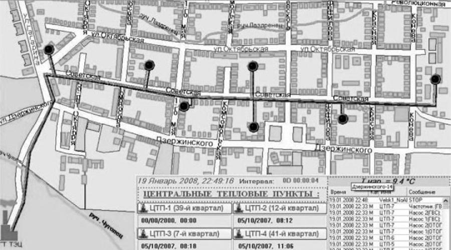
In Fig. 1 shows the main screen of the system. It schematically shows the main heating network indicating the heat source (CHP) and central heating points (from the first to the seventh). The screen displays information about the occurrence of emergency situations at the facilities, the current outside air temperature, the date and time of the last data transmission from each point. Heat supply objects are equipped with pop-up tips. When an abnormal situation occurs, the object on the diagram begins to “blink”, and a record of the event and a red flashing indicator appear in the alarm report next to the date and time of data transmission. It is possible to view enlarged thermal parameters for central heating stations and for the entire heating network as a whole. To do this, you need to disable the display of the alarm and warning report list (the “OT&P” button).

Rice. 1. Main screen of the system. Layout of heat supply facilities in Velsk
Switching to the mnemonic diagram of a heating point is possible in two ways - you need to click on the icon on the city map or on the button with the inscription of the heating point.
The mimic diagram of the heating point opens on the second screen. This is done both for the convenience of monitoring the specific situation at the central heating station, and for monitoring the general state of the system. On these screens, all controlled and adjustable parameters are visualized in real time, including parameters that are read from heat meters. All technological equipment and measuring instruments are equipped with pop-up tips in accordance with the technical documentation.
The image of equipment and automation equipment on the mnemonic diagram is as close as possible to the real appearance.
At the next level of the multi-window interface, you can directly control the heat transfer process, change settings, view the characteristics of operating equipment, and monitor parameters in real time with a history of changes.
In Fig. Figure 2 shows a screen interface for viewing and controlling the main automation equipment (controller and heat calculator). On the controller control screen, it is possible to change telephone numbers for sending SMS messages, prohibit or allow the transmission of emergency and information messages, control the frequency and amount of data transmission, and set parameters for self-diagnosis of measuring instruments. On the heat meter screen, you can view all settings, change available settings and control the mode of data exchange with the controller.

Rice. 2. Control screens for the “Vzlyot TSriv” heat meter and PCD253 controller
In Fig. Figure 3 shows pop-up panels for control equipment (control valve and pump groups). This displays the current status of this equipment, error information and some parameters necessary for self-diagnosis and testing. Thus, for pumps, very important parameters are dry-running pressure, time between failures and start-up delay.

Rice. 3. Control panel for pump groups and control valve
In Fig. Figure 4 shows screens for monitoring parameters and control loops in graphical form with the ability to view the history of changes. All controlled parameters of the heating point are displayed on the parameters screen. They are grouped according to their physical meaning (temperature, pressure, flow, amount of heat, thermal power, lighting). The control loops screen displays all parameter control loops and displays the current parameter value set taking into account the dead zone, valve position and selected control law. All this data on the screens is divided into pages, similar to the generally accepted design in Windows applications.

Rice. 4. Screens for graphic display of parameters and control circuits
All screens can be moved across the space of two monitors, performing multiple tasks simultaneously. All necessary parameters for trouble-free operation of the heat distribution system are available in real time.
How long did it take to develop the system?how many developers were there?
The basic part of the dispatch and control system in Trace Mode was developed within one month by the author of this article and launched in the city of Velsk. In Fig. A photograph is presented from the temporary control room where the system is installed and undergoing trial operation. At the moment, our organization is putting into operation another heating point and an emergency heat source. It is at these facilities that a special control room is being designed. After its commissioning, all eight heating points will be included in the system.

Rice. 5. Temporary dispatcher workplace
During the operation of the automated process control system, various comments and suggestions arise from the dispatch service. Thus, the system is constantly being updated to improve the operational properties and convenience of the dispatcher.
What is the effect of implementing such a management system?
Advantages and disadvantages
In this article, the author does not set out to evaluate the economic effect of implementing a management system in numbers. However, the savings are obvious due to the reduction in personnel involved in servicing the system and a significant reduction in the number of accidents. In addition, the environmental impact is obvious. It should also be noted that the implementation of such a system allows you to quickly respond and eliminate situations that could lead to unforeseen consequences. The payback period for the entire complex of works (construction of heating mains and heating points, installation and commissioning, automation and dispatching) for the customer will be 5-6 years.
The advantages of a working control system can be cited:
Visual representation of information on a graphic image of an object;
As for the animation elements, they were specially added to the project to improve the visual effect of viewing the program.
Prospects for the development of the system
The automatic heat supply control system consists of the following modules, each of which performs its own task:
- Main control controller. The main part of the controller is a microprocessor with programming capabilities. In other words, you can enter data according to which the automatic system will operate. The temperature can change depending on the time of day, for example, at the end of the working day, the devices will switch to minimum power, and before it starts, on the contrary, they will go to maximum in order to warm up the premises before the arrival of the shift. The controller can adjust thermal settings in automatic mode, based on data collected by other modules;
- Thermal sensors. Sensors sense the temperature of the system coolant, as well as the environment, and send appropriate commands to the controller. The most modern models of this automation send signals via wireless communication channels, so laying complex systems of wires and cables is not necessary, which simplifies and speeds up installation;
- Manual control panel. The main keys and switches that allow you to manually control the SART are concentrated here. Human intervention is necessary when conducting test runs, connecting new modules, and upgrading the system. To achieve maximum convenience, the panel is equipped with a liquid crystal display that allows you to monitor all indicators in real time, monitor their compliance with standards, and take timely actions if they go beyond the established limits;
- Temperature regulators. These are actuators that determine the current performance of the SART. Regulators can be mechanical or electronic, but their task is the same - adjusting the cross-section of pipes in accordance with current external conditions and needs. Changing the channel capacity makes it possible to reduce or, conversely, increase the volume of coolant supplied to the radiators, due to which the temperature will increase or decrease;
- Pump equipment. SART with automation assumes that coolant circulation is provided by pumps that create the necessary pressure required for a certain water flow rate. The natural scheme significantly limits the possibilities of adjustment.
As part of the supply of electrical panel equipment, power cabinets and control cabinets for two buildings (ITP) were supplied. To receive and distribute electricity at heating points, input and distribution devices are used, consisting of five panels each (10 panels in total). Switching switches, surge suppressors, ammeters and voltmeters are installed in the input panels. ATS panels in ITP1 and ITP2 are implemented on the basis of automatic transfer switch units. The ASU distribution panels contain protection and switching devices (contactors, soft starters, buttons and lamps) of the technological equipment of heating points. All circuit breakers are equipped with status contacts that indicate emergency shutdown. This information is transmitted to controllers installed in automation cabinets.
To monitor and control the equipment, OWEN PLC110 controllers are used. The OWEN MV110-224.16DN, MV110-224.8A, MU110-224.6U input/output modules, as well as operator touch panels, are connected to them.
The coolant is introduced directly into the ITS room. Water supply for hot water supply, heating and heat supply of air heaters of air ventilation systems is carried out with correction according to the outside air temperature.
Display of technological parameters, accidents, equipment status and dispatch control of ITP is carried out from dispatchers' workstations in the integrated central control room of the building. The dispatch server stores an archive of process parameters, accidents, and the state of ITP equipment.
Automation of heating points provides for:
- maintaining the temperature of the coolant supplied to the heating and ventilation systems in accordance with the temperature schedule;
- maintaining the water temperature in the DHW system when supplied to consumers;
- programming different temperature conditions by hours of the day, days of the week and holidays;
- monitoring compliance with parameter values determined by the technological algorithm, supporting technological and emergency parameter limits;
- control of the temperature of the coolant returned to the heating network of the heating supply system according to a given temperature schedule;
- outside air temperature measurement;
- maintaining a given pressure difference between the supply and return pipelines of ventilation and heating systems;
- control of circulation pumps according to a given algorithm:
- on/off;
- control of pumping equipment with frequency drives using signals from a PLC installed in automation cabinets;
- periodic main/backup switching to ensure equal operating hours;
- automatic emergency switching to a backup pump based on control of a differential pressure sensor;
- automatic maintenance of a given pressure drop in heat consumption systems.
- control of coolant control valves in the primary circuits of consumers;
- control of pumps and valves for feeding heating and ventilation circuits;
- setting the values of technological and emergency parameters through the dispatch system;
- control of drainage pumps;
- monitoring the state of electrical inputs by phase;
- synchronization of the controller time with the unified time of the dispatch system (SOEV);
- start-up of equipment after power supply is restored in accordance with a given algorithm;
- sending emergency messages to the dispatch system.
Information exchange between automation controllers and the upper level (workstation with specialized MasterSCADA dispatch software) is carried out via the Modbus/TCP protocol.