Alarm loop, block diagram, connection. Basic methods of monitoring an alarm loop Radial fire alarm loop what
Read also
An alarm loop (AL) is an electrical circuit containing:
- sensors (DS);
- connecting wires;
- terminal (OU), switching, as well as loop control devices (LCD).
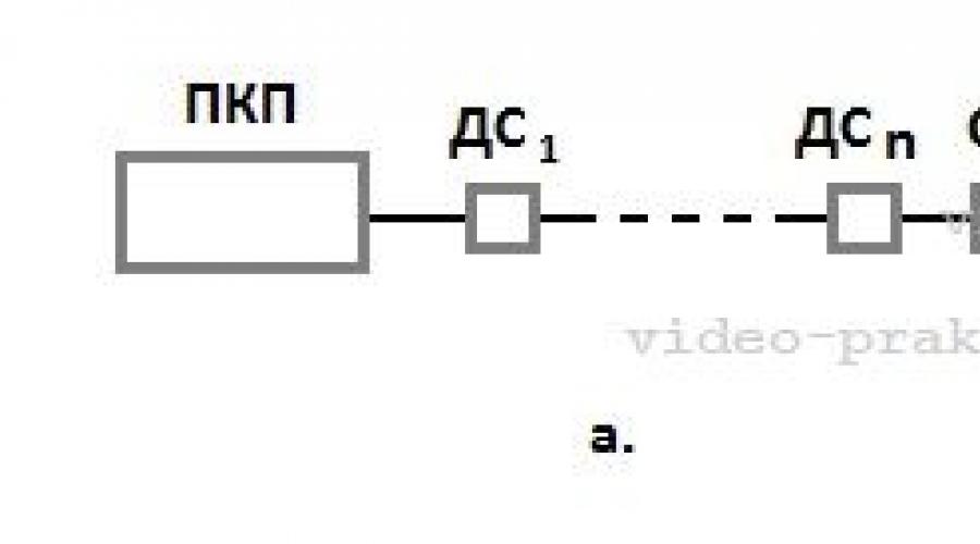
This is the definition for a wired loop, and Figure 1 shows block diagrams of the most common options.
I would like to draw your attention to the ambiguity in the interpretation of the state of dry contacts (relays) in the “classical” technical understanding and use for means burglar alarm. It would be correct to call the contacts normally closed (NC) for a device that has them closed when not in use. For normally open (NO), naturally the opposite is true.
For some reason, alarm sensors (detectors) are considered to be in a closed state when the detector is turned on. Indeed, when the detector is turned on and goes into the “normal” state, the contacts close, but this is a working state, which means they must be considered NR. In order to avoid confusion, it is better to look at how the alarm signal is generated:
- opening;
- or by closing relay contacts.
The vast majority of sensors use the first option (Fig. 1a). I dwell on this in such detail so that you understand the principle of operation of the alarm loop and the security system as a whole. In the security mode, which is characterized by the supply of supply voltage to the detectors and the absence of influences causing the sensor to enter an alarm state, the AL is a closed circuit.
For the control panel (RCD), this is evidence that everything is normal at the controlled object. The control panel monitors the current flowing through the loop and if its value deviates upward or downward, it generates an alarm signal.
In order to provide the required current value, a terminal device is included in the loop - usually a resistor. Terminal devices may consist of other elements or combinations thereof, but this is not typical for most security systems.
By the way, in the passport on control device It is necessary to indicate which element is used as the final element.
In order for current to appear in the loop, voltage must be applied to it. The PKP does this. Its terminal block indicates the polarity of the connection, which sometimes needs to be taken into account - more on that later.
Let's see in what cases the security alarm loop can open.
- as a result of an impact on the sensor, causing it to go into an alarm state;
- loss of supply voltage to active detectors;
- break or short circuit of the electrical circuit.
The first mode indicates intrusion detection (except for cases of false alarms). The other two are the result of various components of the alarm system malfunctioning. By the way, if sensors are used that generate an alarm signal by closing the contacts (Fig. 2b), then in the “alarm” mode the loop will be closed.
TYPES AND TYPES OF SIGNALING LINES
Loops can be classified according to several criteria, for example:
- method of connection to the device;
- types of detectors used.
In the first case, two types can be distinguished: radial (Fig. 2a) and annular (Fig. 2b). The latter is quite rare and is used mainly in address systems fire alarm.

If we talk about the types of sensors used, then we can talk about threshold loops (Fig. 1a-b), which sharply change their electrical parameters when switching to the “alarm” mode, and address ones (Fig. 2c).
I have already talked about the first ones, but let’s look at addressable alarm loops now.
They are called so due to the addressable alarm sensors they use. In this case, information about the state of the sensor (in digital form) is transmitted over one two-wire line and the supply voltage is supplied. Due to the unique address, each detector can be uniquely identified by the system.
In this case, when connecting the loop, observing the polarity indicated on the terminals of the control panel and security sensors is mandatory. In addition, the number of detectors connected to the addressable alarm loop is limited and is determined by the technical characteristics of the device.
INSTALLATION OF SECURITY Loops
Let's start with the fact that the alarm loop is a low-current circuit and its installation must be carried out taking into account the relevant standards and regulations. The main one is to ensure that when laying in parallel with power circuits, the distance between them is at least 50 cm. The intersection of these circuits is allowed only at right angles, etc.
Since when laying the AL it is necessary to ensure its protection from accidental damage, it is not allowed to lay wires without attaching them to load-bearing structures. The most typical example of how not to do it and how it is done anyway is the free placement (dragging) of cables in the ceiling space, for example, behind Armstrong ceilings.
Guiding Documents private security In order to avoid sagging of the connecting lines of security alarm systems, they are prescribed to fasten them in increments of, in my opinion, 50 cm to the walls and ceiling. At open gasket this becomes irrelevant, since there are electrical boxes and corrugated hoses that:
- firstly, they allow you to comply with the rules for laying cables;
- secondly, they simplify and speed up the installation process.
In addition to the requirements for the installation of alarm loops as low-current circuits, there are also rules for ensuring the reliability of their subsequent operation and ease of maintenance. There may be some contradictions here.
For example, from a maintenance point of view, access to the alarm system should be as convenient as possible, and from a security point of view, it is necessary to prevent the possibility of unauthorized access to wires and sensors.
Moreover, if during protected times it is difficult to carry out any manipulations with the loop, then during the period when the alarm system is turned off, it will not be difficult for a knowledgeable person to disable part of the loop or sensors. Moreover, after this the alarm will work as before, only part or all of the premises will be unprotected.
To solve this problem, the following measures can be taken:
- sealing (sealing) of instrument cases, distribution boxes, places of possible opening of electrical boxes;
- hidden installation of alarm sensors;
- installation of loop monitoring devices.
The first two points are quite obvious. The AL monitoring device allows you to determine its breakage. On the one hand, it may indicate a malfunction of the loop, on the other hand, it will indicate that part of the loop is disconnected. The connection of the CCTV is made at the point farthest from the control panel and its visual control must be carried out every time the object is put under protection.
However, what has been said applies to security systems installed in places with a large number of unauthorized persons: shops, offices, etc. The risk of such interference in an alarm system installed in a country house, in a private house or apartment is practically absent.
* * *
© 2014-2020 All rights reserved.
The materials on the site are for informational purposes only and cannot be used as guidelines or normative documents.
Loop monitoring, protection against breakage and short circuit
Neplohov I.G., Ph.D., expert
| IN regulatory documents a requirement is given for mandatory monitoring of the serviceability of fire alarm system (FAS) loops. Indeed, if the loop breaks, depending on the location of the fault, part or all of the fire detectors (FP) are switched off. At short circuit loop (short circuit), all fire detectors connected to it become inoperable. In the simplest systems, control of disconnecting the PI from the socket is ensured by breaking the loop, which blocks FIRE signals from the next PI in the loop. This is a violation of the regulatory requirement for the preferential transmission of FIRE signals in relation to other signals. The article discusses technical solutions that increase the performance of SPS of various levels of complexity in real conditions: the simplest non-addressed, addressable and addressable analogue ones. |
Non-addressable threshold fire alarm systems
In the simplest non-addressable systems, it is quite difficult to protect the loop from short circuits and from breakage using circuitry methods. In clause 17.6.2. NPB 76-98 "FIRE DETECTORS. GENERAL TECHNICAL REQUIREMENTS. TEST METHODS" states: "If the design of the detector provides for its mounting in a socket, then it must be ensured that a fault notification is generated on the control panel when the detector is disconnected from the socket." For this class of systems, this requirement is met by breaking the loop: in each base, separate input and output contacts of one of the loop conductors are installed, which are closed by a jumper located in the PI (Fig. 1). Thus, when the first PI is turned off, the entire loop becomes inoperable and all premises controlled by this loop are left without protection.
This technical solution contradicts the requirements of NPB 75-98 "Fire alarm control devices. Fire control devices. General technical requirements. Test methods", where clause 9.1.1 states: "The control panel must provide ... priority registration and transmission to external circuits of fire notification in relation to other signals generated by the control panel." Breaking the loop when the PI is turned off provides priority to the FAULT signal by blocking the FIRE signals disconnected from the control panel and deprived of power supply to the PI. The relevance of this problem increases with the expansion of the types of premises protected by smoke PIs when they are installed in places with open access. For example, SNiP 01/31/2003 “Residential multi-apartment buildings” prescribes the installation of smoke PIs in non-apartment corridors. , where there is a high probability of their unauthorized shutdown.
Several are known technical solutions to eliminate this shortcoming in non-addressable systems. There are ways that allow you to turn off the fire detector without breaking the loop. long time, which ensures the operability of all remaining PIs in the loop.
1. To generate a FAULT signal for almost any control panel, it is enough to turn off the terminal element of the loop for a time not exceeding 0.3 - 1 second. Thus, after disconnecting the PI from the loop, you can manually eliminate the open loop on the base. The special design of the base and detector makes this operation as easy as possible. For example, in the B401, B401R, B401DG, B312RL, B312NL, E1000B, E1000R, E412RL, E412NL System Sensor bases (for non-addressable fire detectors of the PROFI, 100th, 400th and ECO1000 series) between the input and output terminals of the negative alarm loop bus a spring-loaded contact is installed (Fig. 2), which is fixed in the closed and open state. When installing/removing the detector, the contacts are automatically closed/opened by special structural elements located on back wall detector housing (Fig. 2). When carrying out maintenance of the detector, closing the contacts of the base with the removed detector allows you to maintain the functionality of the remaining sensors. In this case, the period of time during which the loop is in the open state is sufficient for fixing the FAULT mode by the control panel. In addition, closing these contacts before installing the PI can be used when checking the resistance of loops and greatly simplifies this procedure. Moreover, the design of the detector ensures, regardless of the preliminary setting of the position of the spring in the base, the closing of the corresponding contacts of the base when installing the detector, and opening when removing it. This technical solution is universal and can be used with any non-addressable control panel.
2. Using bases with a Schottky diode. More complex technical solutions make it possible to completely avoid disconnecting other detectors from the control panel when removing the PI, while ensuring the generation of a FAULT signal. The base contacts, which open the loop in the absence of PI, are shunted by a Schottky diode in the forward direction at the operating supply voltage of the detectors. When the detector is turned off, in this case, despite the opening of the base contacts, the signal, FIRE, is supplied to the control panel through a diode from any PI in the loop. The System Sensor company produces bases with Schottky diode B401SD and B401RSD.
In European systems, loop control when using bases with diodes is provided different ways, although they are all based on different resistance loop depending on the direction of the current in the loop and are implemented either using complex control panel signals or more complex terminal elements of the loop compared to a resistor. For example, in Fig. Figure 3 shows a system with an active terminal element that generates a sequence of pulses; Schottky diodes are installed in the bases, which are connected in series to the loop when the detector is turned off. In the simplest case, a capacitor is installed at the end of the loop, and the control panel periodically turns off the supply voltage to the loop for a few milliseconds. In normal mode, the capacitance at the end of the loop maintains an almost constant voltage, but when the PI is turned off, the discharge current is blocked by a diode and pulses appear on the loop from the control panel side.
A diode can be used as the terminal element of the loop. In this case, the control panel periodically turns on the reverse polarity of the loop supply voltage for a few milliseconds, at which current passes through this diode. When the detector is turned off, the Schottky diode in the base blocks the flow of current in reverse polarity and the control panel detects a fault. Last method can also be implemented in systems with domestic control panels with alternating voltage in a loop with a diode and a resistor at the end of the loop. With direct voltage polarity, the loop current is determined by the current consumption of the PI, with reverse polarity - by the value of the terminal element resistor.
When the PI is turned off, the presence of a counter-connected Schottky diode in the base reduces the current with reverse polarity to almost zero, which causes the formation of a FAULT signal; at the same time, with the direct voltage polarity, power is provided to all remaining detectors in standby mode and the passage of the FIRE signal from any PI in the loop (Fig. 4).
Constructing a loop with an alternating voltage with diodes in the bases and a resistor at the end of the loop allows you to distinguish a loop with a missing PI from a broken loop. In standby mode, the loop current is determined by the total current consumption of the PI and the value of the terminal resistor. When the polarity of the loop voltage changes, this value changes slightly, and when using detectors with a diode bridge at the input, for example, smoke ionization 1151E, it remains constant. When removing the detector from the base, due to a Schottky diode connected in series, the current with reverse voltage polarity will drop to almost zero, remaining at the same level with direct polarity. A loop break is determined by a decrease in current consumption in both direct and reverse polarity by turning off the terminal resistor.
According to European standards, it is not allowed to block the signals of manual fire call points when the automatic fire detector is turned off. This requirement also contributed to the widespread use of technical solutions that prevent loop rupture when the PI is turned off. Of course, you can include manual PIs either in a separate loop, or in the same loop, but before automatic PIs, however, these solutions require increased costs for cables and installation and reduce the overall performance of the system.
Non-addressable systems with linear smoke PIs
Let's consider connecting non-addressable linear smoke fire alarms with two relays: FIRE - normally open contacts, FAULT - normally closed contacts. Incorrect inclusion of even two linear PIs in one loop can also lead to blocking of the FIRE signal of one PI when the FAULT signal is generated by another PI. The FAULT signal is generated by opening the relay contacts when the beam is blocked or at the limit of the auto-compensation range for filter dust. Opening the FAILURE relay contacts of the first linear PI breaks the loop and turns off, together with the terminal resistor, all the FIRE relays of the remaining PIs. To eliminate this situation, first the FIRE relay outputs of all linear PIs are connected to the control panel, and then all the FAULT relay outputs are connected (Fig. 5). Thus, opening the contacts of any FAULT relay leads to the disconnection of the terminal resistor of the loop, but does not block the FIRE signals of any of the linear PIs connected to this loop.
To increase the reliability of information about the state of the loop in standby mode, some control panels additionally monitor the voltage value directly at the terminal resistor of the loop. For this purpose, a special input is used, to which a class A return loop is connected, in Fig. 5 is shown in dotted line.
The use of a control panel with alternating voltage in the loop and additional Schottky diodes makes it possible to simplify the circuit and save on cables (Fig. 6). The principle of operation is similar to the operation of a loop with a point PI with diode bases: when the contacts of the FAILURE relay open, due to the Schottky shunt diode, with the direct polarity of the loop voltage, communication between the control panel and the FIRE relay of other detectors is ensured, and with reverse polarity, the diode is turned on counter, simulating a break in the loop and The control panel receives a FAULT signal. Some linear smoke detectors, such as the single-component 6500R, have special terminals for connecting a supplied Schottky diode in parallel with the FAIL relay contacts, and terminals for connecting a current-limiting resistor in series with the FIRE relay contacts.
Addressable non-interrogating threshold fire alarm systems
Addressable non-interrogation SPS uses addressable PIs, which transmit address codes of triggered detectors to the control panel. The address of the activated detector is displayed on the control panel display. These systems are the most difficult to protect from breaks and short circuits. Addressable systems allow the use of a larger number of PIs in one loop, compared to non-addressed SPS, because addressable systems are not subject to restrictions on the area protected by one loop and on the location of premises on floors. However, the structure of the loop, as in addressless SPS, remains linear with the terminal element of the loop. When the detector is removed, the loop breaks between the two base contacts, the end element of the loop is switched off, the control panel detects the loop break and generates a FAULT signal. In this case, neither the address of the removed detector nor the fact of its disconnection is determined. Similarly, when the loop breaks, there is no information that allows you to quickly localize and eliminate the fault. Moreover, the presence of code messages during activation limits the possibility of using solutions used in non-addressed systems. Universal solution, used in address systems various types- this is a ring loop with separate inputs and outputs to the control panel.
Addressable interrogation threshold fire alarm systems
Addressed polling SPS periodically polls fire detectors, monitors their performance and identifies a faulty PKP detector, which is required by clause 12.17 of NPB 88-2001* when installing one detector in a room. The use of specialized processors in this type of PI with multi-bit analog-to-digital converters, complex signal processing algorithms and non-volatile memory provides not only the ability to stabilize the sensitivity level, but also the formation of various signals when the lower limit of auto-compensation is reached when the optocoupler is dirty and the upper limit when the smoke chamber is dusty.
In addition, addressable polling systems are quite simply protected from address bus breakage and short circuits. In polling addressable SPS, an arbitrary type of loop can be used: ring, branched, star, any combination of them and no terminal elements are required. In interrogated addressable systems, it is not necessary to break the address bus when removing the detector; its presence is confirmed by responses to the control panel request at least once every 5 - 10 seconds. If the control panel does not receive a response from the detector during the next request, its address is indicated on the display with a corresponding message. Naturally, in this case there is no need to use the loop break function and when one detector is turned off, the functionality of all other detectors is maintained.
To protect the address bus from short circuits, insulating bases are used, which, using electronic keys, automatically disconnect the short-circuited section of the address bus. For example, the B401LI base of the Leonardo series (Fig. 7) has two insulators connected symmetrically with respect to the PI, which allows it to be used in address buses, such as radial type, and circular or mixed type, with branches and ring sections. In Fig. Figure 8 shows a diagram with B401LI insulating bases protecting the branches of the address bus on each floor and sections of the ring address bus in the attic.
Addressable analogue fire alarm systems
An important difference between addressable analogue fire alarm systems and threshold ones is that in them the fire addressable analogue detector only measures the value of the controlled parameter (smoke level or temperature) and transmits these values when the control panel contacts the appropriate address.
The analog addressable control panel (AA PKP) is a specialized computer, a data processing center using the most complex algorithms in real time, provides maximum speed decision making and subsystem management fire automatics, warnings, evacuation and engineering systems object of any complexity with display of the object’s status in the form of text messages. In this case, the development of the fire situation at the facility is analyzed with the formation of warning signals at the earliest stages of the fire at optical density levels 10 - 100 times lower than the threshold PI. The high efficiency of addressable analogue systems determined the appearance in 2002 of a requirement for their mandatory use to protect the residential part of high-rise buildings over 100 meters in height.
The possibility of using addressable analog loops with a large number of automatic and manual fire detectors, control and monitoring modules, addressable sirens, etc., with a total number of up to 200 units and a length of up to 2 km, requires a maximum high level protection against breakage and short circuit. As a rule, a ring cable is used with control of the passage of signals, which, if broken, is automatically transformed by the AA control panel into two radial ones, and all components continue to function. Based on the composition of the addresses of the devices included in the first and second loops, the location of the fault is determined and a corresponding test message is generated.
To protect against short circuits, bases for detectors with insulators, separate insulator modules and isolators as part of monitoring and control modules are used. If the loop is short-circuited, only the section between two devices containing short-circuit insulators is switched off, the rest of the system remains operational (Fig. 9). As with a cable break, a short circuit causes the fault location to be localized and detailed information in text form with recommendations on how to eliminate it is displayed on the AA display of the control panel.
SECURITY - FIRE
Addressable alarm Compared to others, it probably has the only drawback - relatively high cost devices.
Fire alarm
It is generally accepted that it is compensated by lower installation costs compared to a non-addressed system. Undoubtedly, but for fairly large objects. In addition, there are other features of this type of alarm that will be discussed here.
The system under consideration is good, first of all, because one line is enough to connect all the sensors (I’m not taking the power circuit into account yet). Of course, it is impossible to endlessly increase the number of sensors, for example, for the Orion system (I will base further discussion on the example of this system) the maximum number of addressable devices is 127, but this is already a lot, and if the system is correctly configured, the possibilities will be almost limitless.
Figure 1 shows an addressable sensor connection diagram and its non-addressable analogue, where:
- LS - communication line,
- APS - control panel (device),
- PKP - receiving control device,
- ШС - alarm loop,
- And - a detector.
This diagram does not add anything new to the above, but clearly illustrates the difference in the amount of installation work.
I would like to note one more point: addressable fire alarms have two undoubted advantages compared to conventional ones:
- can use, if the room space allows, one fire detector instead of two analogue ones,
- allows you to monitor the status of each sensor individually.
As for the rest, fire and security alarms built according to the address principle do not have significant differences between themselves.
The operating principle of addressable sensors differs from analog sensors in the method of signal transmission. The former transmit information about their status in digital form and, naturally, report their individual number (address), determined when setting up the system.
 One system configuration option (using the example of Orion equipment from NPO Bolid) is shown in Figure 2. Abbreviations and designations are as follows:
- PC - personal computer. On its basis an automated workplace (automated workplace), in addition, it can be used to conveniently program and configure alarms. In the absence of an automated workstation, the constant presence of a PC in the system is not necessary.
- PI - interface converter. The devices exchange information with each other via the RS-485 interface. And they connect to the PC via COM port via RS-232 interface.
- SK - network controller (remote control panel). Manages, coordinates, and saves the configuration of the system as a whole. You can also program the system through it, although it is less convenient.
- BI, BU - here I combined display, control, keyboard, relay modules, etc.
- PKP - receiving control devices, being addressable devices, allow you to connect conventional detectors (I), organized in familiar loops.
- KDL - two-wire line controller - connects addressable detectors (sensors) to the system interface. In addition, in the presence of devices called addressable expanders (AP), it allows the use of conventional detectors, as is the case with control panels.
All devices are assigned individual addresses due to which they are uniquely identified by the system. Each of them has a number of internal settings.
I would like to note that the presence of all of the listed devices is not at all necessary. Addressable systems are built individually for each object, provide a wide range and flexibility of settings, and leave the possibility of subsequent expansion of the system at minimal cost.
ADDRESSED SECURITY ALARM
For large objects, a security alarm built according to the address principle is extremely convenient. This is determined by several factors:
- significant reduction in work on laying connecting lines;
- the ability to localize the state of the system with an accuracy of one sensor;
- ease of subsequent scaling;
- the ability to quickly change the configuration.
The first point is quite obvious and evidence of this is given at the beginning of the article. The same applies to the localization of security detectors.
If we talk about scaling, then during the operation of a security alarm system the need for additional installation of sensors arises quite often. This can be caused by various reasons, including additional blocking of vulnerable areas.
The targeted principle of constructing the system allows us to limit ourselves to installation work directly after installation additional equipment. It is connected to existing connecting lines.
In addition, when the organization guarding the facility changes, the requirements for building the system may also change. Addressable alarm makes it possible to make the necessary changes to its configuration in a matter of hours. Often it is enough to reprogram required zones and sections, which is certainly extremely convenient.
Minimizing costs for installing addressable security alarms.
It is no secret that addressable detectors are quite expensive. To reduce the cost of purchasing them, you can make a compromise. We install conventional non-addressable sensors and connect them to devices called addressable expanders.
Of course, it is impractical to connect one single detector to the expander, so we proceed as follows:
- we equip a separate room or zone using the traditional wired method;
- We “hang” the corresponding group of devices on the expander.
As a result, we get a kind of hybrid that largely has the advantages of an addressable security system, but has a lower cost.
ADDRESSED FIRE ALARM
Here, the need to change the configuration arises quite rarely, except when connecting new premises to an existing fire alarm system or installing additional engineering technical equipment, which must be controlled by the fire protection system.
At the same time, when using addressable fire sensors we have:
- the same savings on the installation of wire loops;
- the ability in most cases to get by with one detector instead of two;
- more simple implementation indicating the status of the alarm system.
In general, targeted security and fire alarm equipment will be more expensive, moreover, it is not a fact that savings on installation work will cover this difference in price. However, the larger the object, the more preferable the address system is, if not in price, then in terms of ease of installation and operation.
© 2010-2018. All rights reserved.
The materials presented on the site are for informational purposes only and cannot be used as guidance documents.
HOME CCTV ACS OPS ITS ARTICLES
SECURITY ALARM LINE
TYPES AND TYPES - INSTALLATION
An alarm loop (AL) is an electrical circuit containing:
- sensors (DS);
- connecting wires;
- terminal (OU), switching, as well as loop control devices (LCD).
This is the definition for a wired loop, and Figure 1 shows block diagrams of the most common options.

I would like to draw your attention to the ambiguity in the interpretation of the state of dry contacts (relays) in the “classical” technical understanding and use for security alarm systems. It would be correct to call the contacts normally closed (NC) for a device that has them closed when not in use. For normally open (NO), naturally the opposite is true.
For some reason, alarm sensors (detectors) are considered to be in a closed state when the detector is turned on. Indeed, when the detector is turned on and goes into the “normal” state, the contacts close, but this is a working state, which means they must be considered NR. In order to avoid confusion, it is better to look at how the alarm signal is generated:
- opening;
- or by closing relay contacts.
The vast majority of sensors use the first option (Fig. 1a). I dwell on this in such detail so that you understand the principle of operation of the alarm loop and the security system as a whole. In the security mode, which is characterized by the supply of supply voltage to the detectors and the absence of influences causing the sensor to enter an alarm state, the AL is a closed circuit.
For the control panel (RCD), this is evidence that everything is normal at the controlled object. The control panel monitors the current flowing through the loop and if its value deviates upward or downward, it generates an alarm signal.
In order to provide the required current value, a terminal device is included in the loop - usually a resistor. Terminal devices may consist of other elements or combinations thereof, but this is not typical for most security systems.
By the way, the passport for the control device must indicate which element is used as the terminal element.
In order for current to appear in the loop, voltage must be applied to it. The PKP does this. Its terminal block indicates the polarity of the connection, which sometimes needs to be taken into account - more on that later.
Let's see in what cases the security alarm loop can open.
- as a result of an impact on the sensor, causing it to go into an alarm state;
- loss of supply voltage to active detectors;
- break or short circuit of the electrical circuit.
The first mode indicates intrusion detection (except for cases of false alarms). The other two are the result of various components of the alarm system malfunctioning. By the way, if sensors are used that generate an alarm signal by closing the contacts (Fig. 2b), then in the “alarm” mode the loop will be closed.
TYPES AND TYPES OF SIGNALING LINES
Loops can be classified according to several criteria, for example:
- method of connection to the device;
- types of detectors used.
In the first case, two types can be distinguished: radial (Fig. 2a) and annular (Fig. 2b). The latter is quite rare and is used mainly in addressable fire alarm systems.

If we talk about the types of sensors used, then we can talk about threshold loops (Fig. 1a-b), which sharply change their electrical parameters when switching to the “alarm” mode, and address ones (Fig. 2c).
I have already talked about the first ones, but let’s look at addressable alarm loops now.
They are called so due to the addressable alarm sensors they use. In this case, information about the state of the sensor (in digital form) is transmitted over one two-wire line and the supply voltage is supplied. Due to the unique address, each detector can be uniquely identified by the system.
In this case, when connecting the loop, observing the polarity indicated on the terminals of the control panel and security sensors is mandatory. In addition, the number of detectors connected to the addressable alarm loop is limited and is determined by the technical characteristics of the device.
INSTALLATION OF SECURITY Loops
Let's start with the fact that the alarm loop is a low-current circuit and its installation must be carried out taking into account the relevant standards and regulations. The main one is to ensure that when laying in parallel with power circuits, the distance between them is at least 50 cm.
How does an addressable fire alarm system work?
The intersection of these chains is allowed only at right angles, etc.
Since when laying the AL it is necessary to ensure its protection from accidental damage, it is not allowed to lay wires without attaching them to the supporting structures. The most typical example of how not to do it and how it is done anyway is the free placement (dragging) of cables in the ceiling space, for example, behind Armstrong ceilings.
The governing documents of private security require, in order to avoid sagging of the connecting lines of security alarm systems, to fasten them in increments of, in my opinion, 50 cm to the walls and ceiling. With open installation, this becomes irrelevant, since there are electrical boxes and corrugated hoses that:
- firstly, they allow you to comply with the rules for laying cables;
- secondly, they simplify and speed up the installation process.
In addition to the requirements for the installation of alarm loops as low-current circuits, there are also rules for ensuring the reliability of their subsequent operation and ease of maintenance. There may be some contradictions here.
For example, from a maintenance point of view, access to the alarm system should be as convenient as possible, and from a security point of view, it is necessary to prevent the possibility of unauthorized access to wires and sensors.
Moreover, if during protected times it is difficult to carry out any manipulations with the loop, then during the period when the alarm system is turned off, it will not be difficult for a knowledgeable person to disable part of the loop or sensors. Moreover, after this the alarm will work as before, only part or all of the premises will be unprotected.
To solve this problem, the following measures can be taken:
- sealing (sealing) of device housings, distribution boxes, places where electrical boxes may be opened;
- hidden installation of alarm sensors;
- installation of loop monitoring devices.
The first two points are quite obvious. The AL monitoring device allows you to determine its breakage. On the one hand, it may indicate a malfunction of the loop, on the other hand, it will indicate that part of the loop is disconnected. The connection of the CCTV is made at the point farthest from the control panel and its visual control must be carried out every time the object is put under protection.
However, the above applies to security systems installed in places with a large number of unauthorized persons: shops, offices, etc. The risk of such interference with an alarm system installed in a country house, in a private house or apartment is practically absent.
© 2014-2018 All rights reserved.
The materials on the site are for informational purposes only and cannot be used as guidelines or regulatory documents.

Heat detector "Bolid"
Fire, in addition to light and heat, if handled carelessly or due to a coincidence of circumstances, can bring a lot of troubles and destruction. This is especially true for multi-story buildings with their huge vertical air draft and storage facilities with explosives.
The only way to save people's lives, personal and government property from destruction in fire is to install fire alarm systems on site. “Bolid” detectors of various types are indicators that can quickly signal the start of a fire.
Purpose and areas of application
Bolid detectors are the basis of the fire security system. With their help, the surrounding space is monitored, scanned, information is processed and sent to control devices.
On a note: With the help of various Bolid detectors, devices are activated, both signaling fires and fire extinguishing systems.
Since a fire is characterized by factors such as increased temperature, smoke and ultraviolet radiation, Bolid detectors are manufactured to respond to these signs of fire.
Thus, in fire alarm systems, fire detectors “Bolid” of this type are used:
- Flame detectors.
- Thermal sensors.
- Smoke detectors.
- Combined instruments.
The most functional is aspiration detector A “car” that actively scans the surrounding space, analyzing its indicators such as heat, smoke and gas pollution. It is distinguished not only by its versatility, but also high price, which starts from 20,000 rubles.
Flame detectors

Flame sensors
Flame detectors "Bolid" are used in places where explosive and flammable substances are stored. In addition, this is the only type of sensor that can operate on open areas. Air movement on open area makes it impossible to use smoke, heat and gas detectors.
Flame detectors are used at the following facilities:
- offshore drilling rigs;
- decks of tankers transporting oil and liquefied gas;
- gas and oil production installations;
- gas pipelines;
- petrochemical industry enterprises;
- gas stations;
- warehouses with explosives and flammable substances;
- pyrotechnic factories.
The task of the "Bolid" flame detectors is to detect a fire at the moment of its occurrence, with subsequent implementation automatic system fire extinguishing
The operating principle of Bolid detectors of this type is to detect ultraviolet radiation, which is characteristic only of flame. Sensors do not respond to light from lamps, solar radiation and heat. The degree of reliability of these devices corresponds to their price, which ranges from 40,000 to 70,000 rubles.
Thermal sensors
These devices are designed to provide an appropriate signal when the temperature at a protected facility increases. For indoor use only. They issue a signal when a threshold temperature level is reached or based on the results of an analysis by the device of the rate of its increase.
The "Bolid" addressable heat detector detects fire in a comprehensive manner - in both ways, which increases the reliability of the device and eliminates the giving of false signals. Heat detectors“Bolid” can be installed in rooms with or without heating.
Their installation location can be:
- garages;
- premises in offices and other similar institutions;
- trading, entertainment centers and sports facilities;
- warehouses for materials with a slow burning rate;
- medical institutions;
- schools and kindergartens.
Thanks to simple device, low price (200-500 rubles) and ease of installation, thermal sensors are in great demand and popularity among many organizations.
Smoke detectors

Smoke sensor
In terms of the speed of detecting signs of fire, Bolid smoke detectors occupy a middle position between fire and heat detectors. Sensors of this type can operate both as part of alarm systems and independently.
There are two types of smoke capture devices - point and linear:
- Point sensors consist of a housing, a smoke chamber, an optical unit and printed circuit board. They are usually installed on ceilings and control certain area. They have a small cost, in the range of 300-500 rubles.
- The linear detector "Bolid" is a optical system, consisting of both a transmitter and a receiver. They are installed at different ends of the premises, as close as possible to the ceiling, and control a significant distance (50-140 m). Modern linear emitters are equipped with a self-monitoring system that amplifies the signal when the optics become dusty. Their price is quite high (from 4,000 rubles), but this is compensated by the lack of an abundance of wires and the speed of installation.
They are installed only in enclosed spaces.
These can be the following objects:
- kitchens and corridors in residential apartments;
- agricultural buildings - cowsheds, pigsties, poultry farms and granaries;
- garages and underground parking;
- warehouses and storage facilities;
- cabins of ships and ships;
- aircraft cabins and luggage compartments;
- passenger railway cars;
- basements, entrances of various buildings and structures;
- schools, kindergartens, clinics and hospitals;
- repair shops and car services.
IN smoke detectors an electron-optical system is used. The principle of its operation is based on changing electrical parameters photo sensor when air transparency decreases. Smoke detectors have a sufficient degree of reliability and speed of fire detection. Thanks to this and their affordable price, they are most popular.
Combined detectors

Combination device
These devices combine gas, smoke, heat sensors and sensors that capture infrared radiation.
Features of addressable fire alarm
Allows you to detect a fire at its most early stage. Different systems duplicate each other, eliminating errors and false signals.
Combined devices can operate autonomously and as part of security systems.
They perform the following functions:
- Measure the air temperature.
- Air is taken and chemically analyzed for the presence of combustion products.
- Monitor the presence of smoke in the room.
- Using IR sensors, they scan the space to detect radiation of a given range.
- Conduct digital processing information received.
- They supply information to the indicator and to the security system loop.
These products are installed at the following facilities:
- offices of management personnel and in places where valuable equipment and important documentation are located;
- banking institutions and savings banks;
- warehouses and storage facilities with flammable materials.
With a high degree of reliability, these devices have completely affordable price, which ranges from 1000-1800 rubles.
Addressable sensors "Bolid"

Addressable detectors
Addressable sensors "Bolid" are used in systems fire and security alarms. With the help of software, such a device has its place on the diagram, and the operator can determine the place where the alarm signal comes from.
Address security detectors"Bolid" are available in two types:
- Manual. Switching on and off devices of this type is done manually by pressing a button. The Bolid addressable manual fire call point is one example of such a device.
- Radio channel fire detector "Bolid". This type of sensor receives and transmits signals via radio, with a range of up to 600 meters.
The use of radio-channel smoke and heat addressable detectors "Bolid" allows not only to speed up the process of installing an alarm system, but also to significantly reduce its cost by reducing cable consumption and the amount of work.
Programming of the Bolid addressable sensors is carried out after they are installed in place and tested for functionality. This is done from the control panel or personal computer. The device can be assigned absolutely any number, regardless of what it had before. To do this, you need to enter the appropriate command to change the old address and dial the new address.
The use of addressable sensors allows you to accurately determine the location of a fire and take timely measures to eliminate it and evacuate people from the building.
Video about fire detector
Home >> About the company >> Articles and publications
print version
Eternal theme: 1, 2, 3 or 4? Fire detectors for one room
How many fire detectors, what types and to generate what signals should there be in one room?
 A.M. Omelyanchuk
Head of the design bureau of the company "SIGMA-IS"
The question of the number of fire detectors in one room has recently been considered almost indecent. The specialists frown or laugh, but avoid the question, usually making a joke, saying, put a 4 - it’s better to be on the safe side. Or they begin to talk about how SP5 should be changed so that everything is correct and understandable. On the other hand, design practitioners are now forced to create projects based on the existing SP5.
Without claiming to be comprehensive possible situations, I'll try to explain practical recommendations based on the already accumulated experience of living with technical regulations and new sets of rules.
What is mandatory and what is the exception?
Requirements for the number of detectors are specified in SP 5.13130.2009 in paragraphs 13.3.2-13.3.3 and 14.1-14.3 and appendices O and R. I will not quote the text in full - the main points are very long and not very clear. If you want, find it and read it. Just keep in mind that there were minor changes to clause 14.2 this summer to make it a little clearer.
The greatest discrepancy in relation to the main text (sections 13 and 14) is caused by the question “Is it necessary to comply with all of the specified points or do some of them describe exceptions, and from what requirements of which points are exceptions made in this case?”
In general, the most logically consistent interpretation seems to me to be that given in Table. 1.

Applicability of Annex P
Now a few explanations on how to determine which cell of the table. 1 applies to your specific case.
Appendix P is mentioned in the paragraph where it talks about the use of “increased reliability detectors”, and it, in theory, describes the characteristics of such (increased reliability) detectors.
Precise to the spark. How does an addressable fire alarm system work?
As can be seen in table. 1, the applicability of Appendix P can greatly influence the answer. I will give this application in full:
R.1 Use of analysis equipment physical characteristics fire factors and (or) the dynamics of their change and providing information about its technical condition (for example, dustiness).
R.2 Use of equipment and its operating modes that exclude the impact on detectors or loops of short-term factors not related to fire
The applicability of Appendix P to specific detectors is a matter of faith and marketing efforts by the manufacturer.
- If you say that no existing detector satisfies these requirements, I cannot argue with anything. Indeed, it is impossible to protect against all short-term factors. Indeed, detectors do not analyze physical characteristics - they simply measure them.
- If you say that any (at least any optical) smoke detector satisfies these requirements, I will also have to agree. Indeed, all detectors are tested for pulsed electromagnetic interference. Indeed, all detectors detect changes in certain physical parameters environment associated with fire (fire factors).
In practice, it is usually considered that all addressable analogue detectors certainly satisfy Appendix P, while non-addressable ones do not (I repeat once again, “home alone” type detectors, in my opinion, are better than conventional non-addressable ones, but are they good enough to fall under Appendix P is a matter of trust in a particular manufacturer).
Applicability of Appendix O
The appendix is long and I won’t quote it in full. Briefly, its essence is that the estimated time for detecting and eliminating a malfunction (replacing a detector) should not exceed 70% of the permissible time to stop the enterprise’s activities or the time for which control functions can be “transferred to dedicated personnel.”
Please note that this implies an immediate shutdown of the organization’s activities for the duration of a malfunction of even a single detector. Although standard technique Risk calculation considers a normal situation when the alarm system in each room does not work 20% of the time. Therefore, if you draw up STU (special technical conditions) for your facility with risk calculations, you will be able to justify the very leisurely work of the repair service and, of course, without any stoppage of the enterprise’s activities.
What is important for us now is that in order to apply Annex O, it is necessary that the indication of a faulty detector on the control panel be provided. The address systems known to me provide this. The admissibility of applying this paragraph in the case of non-addressed detectors of the “home alone” type and similar ones, capable of generating such a notification on non-addressed loops, can be challenged by representatives of the State Fire Inspectorate, although in the case of installing only one such detector on a non-addressed loop, the requirement is undoubtedly met. The point is that these non-addressable detectors indicate only the fact of a malfunction, and in order to identify the specific detector that generated this event (if there are several of them on a loop), you need to personally go around the entire loop and find the faulty one with your eyes.
Recommendations for talking with the inspector Now let’s forget about “alarm only,” because any alarm with a siren is already a “type 1 warning system.” Taking into account the indicated notes (that any addressable systems can be brought under Appendix O, and addressable analog systems under Appendix P), and also taking into account that almost all domestic non-addressable devices are two-threshold, we can shorten the table. 1 to easy to remember table. 2.

Let me remind you that, following the letter of the law, addressable and addressable-analog devices in themselves do not have any advantage. Formally we're talking about about “increased confidence” or “fault detection”. But since today there is no clear explanation of what kind of malfunctions should be detected, in what time, and even more so there is no clear formulation of what “increased reliability” is, then in the practice of approving projects in the examination and in the practice of carrying out gas pumping inspections, approximately the following understanding has developed .
Do not forget, the interpretation of the vague wording of the set of rules by a particular expert or inspector may differ from mine, and it is useless to refer to my article in a conversation with him. They will very easily explain to you that any multi-criteria addressable analogue laser blue detector does not sufficiently comply with Appendix P. However, if the inspector is not just looking for something to complain about, but is already in the mood for a constructive conversation, then the above interpretation will most likely be suitable. Just remember that application of Appendix O may require a time estimate agreed upon by the customer to replace a faulty detector.
For large rooms
Now remember that all of the above applies to small rooms. If the room is large, then there will obviously be a lot of detectors, spaced at distances no greater than the standard ones - depending on the height of the ceiling, the type of detector and the size of the room. In this case, the question is formulated differently: is it necessary to use half the standard distance between detectors or is it not necessary to use half the distance. I present it in the form of a table. 3.

Please note that Appendix O in in this case does not play any role, because in each room, undoubtedly, there are more than two detectors, and therefore the question of redundancy due to the failure of a separate detector no longer arises.
What will European standards bring?
In conclusion, I will say that after the transition to a method for testing detectors that complies with European standards (fire tests), I see no point in clinging to the remnants of “sovereign fire standards” and expect a very rapid transition completely to European standards (EN 54), in which questions “1, 2, 3 or 4?", included in the title, is simply not there.
Archive of publications
 How to save your property, and sometimes even your life, from the destructive power of fire? Follow the rules for using electrical appliances, do not smoke in bed, and do not allow children to play with matches.
This list can be continued, but what if the fire happened at night or during the day when no one was in the apartment?
Of course, the neighbors, hearing the smell of smoke, will call rescuers, but will they arrive in time? The ideal answer to all these questions is to install an alarm system in the room, the main element of which is an addressable smoke fire detector.
He will be able to send a signal to the control panel immediately when the first signs of fire appear and thereby help save your property from fire.
- Design and principle of operation
- Scope and areas of application
- Model overview
- Advice and opinions from experts
- Let's sum it up
Sensor design and operating principle
Addressable smoke sensors are an important component of the alarm system. It transmits encoded information to the control panel, which includes the address of the device itself or its personal number in the loop, as well as controlled parameters. At the same time, it can also be used to receive a signal to turn on the indicator.
 Very often, addressable detectors are produced for a specific device. They are capable, depending on the type, of transmitting information about the level of smoke or temperature in the controlled building. The control panel, having received them, analyzes the information and submits it to the operator, and also turns the equipment on or off.
A significant number of such devices can be included in one loop, and each of them will have its own unique number, which can be easily determined from the remote control. This approach makes it easy to determine in which room the alarm went off.
It can be powered either through a separate pair of wires or through the same one through which information is exchanged. This approach is used in many systems:
Application area
What is this system alarm? It was first developed and implemented by foreign specialists and only then was it appreciated by domestic companies.
What is addressable fire alarm and what are its advantages?
The same fire detector remains its main component. And as before, the efficiency of the entire system depends on its quality and reliability. However, significant differences also emerged.
 Each sensor is constantly in the process of communicating with the central console, reporting to it information about its status, which includes information about:
- Smoke
- Component performance
- Dust levels
Moreover, each detector has its own communication channel, and the connection can be made by any of available ways. Therefore, it is allowed to install address sensors in fewer quantities than threshold ones.
There are differences in the topology of the circuit construction and the algorithm for polling devices. The control panel of the addressable polling system cyclically polls detectors to determine their status.
In this case, one of four types of signals can come from the device:
- Norm
- Absence
- Malfunction
- Fire
The advantages of address systems include:
- Possibility of monitoring the operation of detectors
- Value for money
- Informativeness of messages
But at the same time they have one significant drawback– increase in fire detection time.
Review of popular models
On modern market fire systems, addressable detectors are presented in a wide range. Among them most in demand The following models are used:
- Smoke optical-electronic (2251EM)
- Thermal maximum differential (5251REM)
- Threshold (5251NTEM)
- Combined (2251TEM)
- Laser (LZR)
- Optical Smoke (FTX-P1)
In them, information is transmitted using digital messages generated by a microprocessor board. They are received by addressable control panels, modules and expanders.
 As an example, we can consider addressable fire alarm sensors developed by one of the most famous foreign System companies Sensor, IP212/101-3A-AIR. It combines optical-electronic and thermal maximum-differential sensors, which has significantly increased the efficiency of signaling. When used, it provides protection against any type of fire.
 This device fully complies regulatory requirements, which allows you to install one addressable detector in a room, instead of two addressless ones.
When a fire is detected, it transmits a “fire” signal to the control panel. These sensors are mainly used for industrial enterprises and other social and cultural institutions.
Efficiency of address systems - expert opinion
Why are such systems most often chosen? Because when installing them you can significantly reduce installation costs and Consumables. Addressable systems are able to monitor the status of detectors, thereby significantly increasing operational reliability. They help reduce labor costs service maintenance, thanks to the use of a ring structure of the address communication line.
Another important positive factor is the possibility of addressable control of all automation. It must be taken into account that everything addressable devices connected to a common communication line, and this made it possible to avoid laying additional circuits.
Bottom line
 Admiring the capabilities, criticizing the high cost and arguing about the areas of application of addressable systems, one cannot achieve full description their effectiveness.
After all, most of the reasoning is superficial. And an objective assessment can only be obtained by analyzing the opinions of all interested parties, including manufacturers.
They are the ones who know everything about their systems and are able to tell what the advantages of their equipment really are. And addressable sensors actually have enough capabilities to work effectively.
They allow you not to waste precious time for such situations and allow the entire system to function extremely harmoniously. And this in turn guarantees reliable protection your property from fire.
To provide uninterrupted operation Fire alarm sensors are connected to warning devices and the dispatcher's console via wires (loops). The cables also transmit control messages, optical signal, etc. Types of fire alarm loops are divided according to their structure; the requirements for them are specified in SNiP and Federal Law No. 123.
Requirements for fire alarm wires
All basic requirements for fire alarm loops are to ensure that the system remains operational in the event of a fire for the required time. Ideally, the cable should have the same degree of fire resistance as the room.The terminal device of the loop is provided with additional structural or any other fire protection.
According to the Federal Law, cable standards are regulated by decree dated July 10, 2012. In particular it is indicated:
- The resistance of the fire alarm loop must withstand exposure to an open flame for a specified amount of time. The functionality of the warning and alarm systems is maintained in full until employees and visitors leave the building.
- It will help you choose cables that comply with GOST. The designation of fire alarm loops is regulated by the Federal Law, therefore the wire marking must be present on the winding.
- Horizontal and vertical are protected by non-combustible structures and fire protection. Standards for laying fire alarm cables require the use of a wire with a heat-resistant winding. Inside the ceiling walls, voids and niches, installation is carried out in a corrugated pipe. When laying open fire alarms, non-flammable wire is used.
- The passage of cable lines through walls requires mandatory treatment with fire retardants. During the work, sealing of joints and others is carried out. The method of laying through the walls is determined taking into account technical characteristics building, its fire hazard. The necessity of laying in boxes is determined by the degree of fire hazard of the room.
- Laying with other cables is permitted provided that there is a thermally insulating winding.
- Fire alarm maintenance must be carried out by a specialist, a representative of the company that installs the warning systems.
To determine the location of a fire, it is necessary that all systems are in working order. For fire alarms, a cable resistant to open exposure fire. The fire resistance limit is calculated according to the PPB requirements for load-bearing structures in the room.
Types of loops for fire alarms
Selection of cable cross-section, maximum length PS loop and many other aspects are calculated after selecting the sensor connection diagram. There are several basic ways to accomplish this task:- Threshold systems with radial loop. One control device, a monoblock, is able to service no more than ten lines and sensors. Increased capabilities are achieved by installing another loop control unit. The system received its name due to the operating principle used. Each sensor has its own sensitivity threshold. When it is reached, an alert is triggered.
The disadvantage of the threshold system is a large number of false signals. Laying together with other cables only aggravates the situation. Another disadvantage is the impossibility precise definition fire places. The system only notifies about a line break, so you have to check the entire radial type loop.
The advantages of the solution include low cost equipment and installation work. - Threshold structures with modular loop. Practically no different from the previous scheme. The difference is that the module used can control the operation of many lines simultaneously. The loop parameters allow you to duplicate the alert signal by connecting two-threshold structures.
- Addressable analog lines. The system is controlled by a module to which a ring cable is connected. The difference between an addressable analog device is that the sensor itself does not make a decision about the presence of a fire, but simply transmits the necessary information to the remote control.
A system with a ring construction of loops allows you to filter out unnecessary information. The signal is duplicated and transmitted to the control panel. The analysis makes it possible to distinguish fire cases from cable breaks and other loop faults. Transit installation allows the use of cable lengths up to 2000 m. - Combined systems. To output a signal to the dispatcher, both threshold and analog equipment are used. Modern alarm system, which takes into account all the shortcomings of the previous lines. The loop troubleshooting algorithm is simplified thanks to the use of a ring circuit.
Combined systems can be used both indoors and outdoors. In the second case, a shielded outdoor cable is used.
For some categories of premises, PPB establish certain restrictions on loops. Installation of exclusively non-flammable wire, inadmissibility of hidden wiring, installation in a cable tray - these and other restrictions are described in SNiP 3.05.06-85 and VSN 116-87.
What cable is needed for PS?
 The brand of wire for installation is determined by the fire hazard category of the building and installed system alerts. The decision to use thermal cables and other types of materials is made during the development of design documentation.
 When choosing a cable, the following indicators play an important role:
- Section calculation. Insufficient power and bandwidth can lead to inaccurate sensor readings. In the case of threshold systems, a low-current cable can cause constant false alarms.
- Sufficient cable protection. In addition to thermal insulation and the presence of a non-flammable winding, it may be necessary to reduce the sensitivity of the loop. In a normal situation, you can immediately use a protected wire. But if, due to oversight or other reasons, the substation malfunctions due to the sensitivity of the cable, the insulation resistance of the loop is measured.
- Marking. The fire resistance limit of the cables, the presence of cable shielding and other indicators must be indicated on the wire winding. The rules for marking cable lines also require indicating the coefficient of smoke and flammability.
- NG - non-flammable - has a classification according to fire resistance from A to D.
- LS - recommended gasket explosive areas, as well as in a group tray. Do not emit harmful fumes during combustion.
- HF – when burning, they do not emit substances with high corrosive properties. Laying in a cable tray together with other alarm wires is allowed.
Standards for laying loops depend on the alarm system used and the current PPB requirements. The list of cables acceptable for use is given in SNiP and PUE. Violations of the recommendations lead to a malfunction of the PS.
If the cable does not comply with the standards, if this is detected, the inspector of the Ministry of Emergency Situations will write explanatory note and will bring to administrative responsibility indicating the timing of replacement of existing loops.
Methods for laying PS cables
Installation and maintenance of the alarm system is described in VSN 116-87, Additional requirements are in SNiP 3.05.06-85. Among all the instructions, the following can be highlighted:
Alarm loop (AL) is one of the components object system security and fire alarm system. This is a wire line that electrically connects the remote element (elements), the output circuits of security, fire and security-fire detectors with the output of control panels. A fire alarm loop is an electrical circuit designed to transmit alarm and service messages from detectors to the control panel, as well as (if necessary) to supply power to the detector. The AL usually consists of two wires and includes remote (auxiliary) elements installed at the end of the electrical circuit. These elements are called load or terminating resistor.
Let's consider a two-wire alarm loop. As an example, Figure 2.4 shows a combined fire alarm with a load Rn at the end.
Rice. 2.4 Combined fire alarm loop with load Rn at the end
In addition to the load resistance, there are a number of factors that create additional load in the AL circuit - this is the equivalent resistance of the AL wires themselves, the “leakage” resistance between the AL wires and between each loop conductor and the “ground”. The permissible limit values of these parameters during operation are indicated in the technical documentation for a specific device. The AL input is connected to the elements of the control panel.
AL is one of the most “vulnerable” elements of an on-site fire and security alarm system. It is exposed to various external factors. The main reason for the unstable operation of the system is the violation of the loop. During operation, a failure may occur in the form of a break or short circuit of the loop, as well as spontaneous deterioration of its parameters. It is possible to deliberately interfere with the electrical circuit of the loop in order to disrupt its proper functioning (sabotage). At the connection points of the AL, its fastening and laying, current “leakages” may form between the wires and conductors to the “ground”. The “leakage” resistance is greatly influenced by the presence of moisture. For example, in rooms with high humidity, the resistance between the wires reaches several kOhms.
Let's consider the most common AL methods:
With a description of the direct current loop, used as a remote element by a resistor;
With AL power supply with alternating pulse voltage and used as a load by series connected resistors and a semiconductor diode;
With AL power supply with pulsating voltage and used as a remote element - a capacitor.
The control method with a direct current power supply involves continuous monitoring of the input resistance of the alarm loop. Figure 2.5 shows a diagram of a typical control unit of a control panel. In the AL control unit, the input resistance is determined by the amplitude value analog signal Uk, removed from the divider arm, which is formed by an AL with an input resistance Rin and a measuring element - a resistor - R and:
U = U p R in / (R in + R and)

Rice. 2.5. Diagram of a typical control unit of a control panel.
The output of the analog-to-digital converter (ADC) is set to
Two voltage thresholds corresponding to the upper and lower limits of the zone of permitted values of the AL input voltage. During operation and changes in the AL resistance and “leakage” resistance, the AL input resistance should not go beyond the permissible values. Because exact value threshold can only be set with a certain error determined by the technological spread R and the error of the ADC, then in this case under valid value This implies upper and lower threshold zones. When R reaches the upper (which corresponds to a break in the alarm loop) or lower threshold (which corresponds to a short circuit of the alarm loop conductors), the device must switch to alarm mode. The optimally selected value is considered to be the value of the remote resistor (load resistance), which ensures control of the alarm loop with the specified parameters and generation of an “Alarm” notification when the detector installed in this alarm loop is triggered.