Power supply circuits for lighting electrical installations in industrial and residential buildings. Power supply for lighting installations Power supply for lighting installations
Read also
Lighting networks of industrial enterprises are divided into two groups: supply and group. Supply networks are laid from the low-voltage switchboard of the transformer substation to group panels, and group networks - from group panels to lamps and plug sockets. Power supply for lighting installations comes from common transformers. According to the PUE, emergency lighting fixtures are connected to independent power sources, such as substation busbar sections powered by different transformers, batteries and diesel generators. Sometimes provision is made for the use of work lighting networks to power emergency lighting fixtures.
In this case, when the working lighting is turned off, the emergency lighting is automatically switched to an independent power supply source.
The configuration of power supply circuits depends on the requirements for lighting installations, the level of reliability of the overall power supply circuit of the enterprise, the number of group lighting panels, the length of lighting networks, etc.
In a three-phase AC system, several group network schemes are used: two-wire single-phase, two-wire two-phase, three-wire two-phase with a neutral wire, three-wire three-phase, four-wire three-phase with a neutral wire. In networks with an isolated neutral, two-wire single-phase, three-wire three-phase and two-wire two-phase circuits are used.
The supply of power and lighting loads in an enterprise from low-voltage buses of substations with one or two transformers is usually carried out using separate lines.
The least reliable lighting circuit is when powered from a substation with one transformer, since when it is turned off, the supply of voltage to the lighting network is completely stopped. A more reliable power supply scheme for lighting installations will be in the case when working and emergency lighting receive power from different transformers in a substation with two transformers. If one of the transformers fails in the production premises, the lamps connected to the power supply from another transformer remain in operation.
Rice. 52. Diagram of the lighting network with a transformer-main unit system:
1 - highway; 2 - disconnector; 3 - power load; 4 - working lighting; 5 - emergency lighting; 6 - secondary lines.
At large enterprises, lighting networks are powered according to the transformer-mains block diagram (Fig. 52). In the event of an emergency shutdown of one of the transformers, its load is switched to the transformer that remains in operation. Emergency lighting is connected to the adjacent transformer substation.
The highest reliability of power supply to lighting electrical installations is obtained when the transformers of both transformer substations are powered from different power plant generators or from different power supply substations of the power system.
In two-wire lighting networks of explosive premises, control and protection devices are installed in the phase and neutral wires, while an additional wire is laid for grounding (in a two-wire circuit where the neutral wire is used for grounding, as well as in three- and four-wire lines, it is prohibited to install fuses in the neutral wires ).
Lighting control devices in small rooms are placed in the room itself, close to the entrance, on the side of the door handle, and in damp, fire and explosive areas and outdoors.
To turn on the lighting of production buildings and external lighting, automatic machines, magnetic starters and general-purpose contactors are used. Switching on and off can be manual or automatic. When automatically turned on Lighting networks use photo relays, which give a signal to turn on depending on the decrease in the level of illumination of natural lighting and a signal to turn off when the illumination increases to a certain level (Fig. 53).

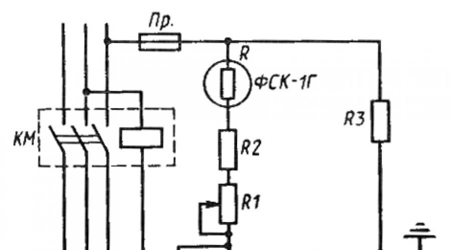
Rice. 53. Scheme of photo relay type FR-1
Photoresistor R type FSK-1G is installed outdoors. The winding of the polarized relay RP is connected in series to the photoresistor circuit. During the day, the resistance of the photoresistor is low, so a large current flows through the winding of the polarized relay RP, connected in series with it, and its contacts are open (thereby the magnetic lighting control starter is turned off). When the external illumination decreases below the set level (5 lx), the resistance of the photoresistor increases, the current through the winding of the relay RP decreases and it turns off, opening the contacts. This causes the magnetic starter to turn on through an additional OLTC relay. When the illumination increases to 10 lux, the RP relay is activated again and the lighting is turned off.
Supply lines in lighting networks include networks from the power source (transformer substation or input into the building) to group electrical panels. The lines going from group electrical panels to lamps are called group.
The power lines of lighting installations, as well as power lines, can be made according to mixed circuits.
The radial scheme is used extremely rarely. This is due to its high cost and high consumption of non-ferrous metals. The basis for choosing a power supply circuit for lighting electrical installations is the requirements for, convenience and ease of management and operation, as well as cost-effectiveness.
Lighting schemes for industrial buildings
The most important of the above requirements is the reliability of power supply. After all, suddenly the lights go out can lead not only to the shutdown of production processes, but also to accidents with people. That is why for many civil and industrial buildings the PUE requires the creation of emergency lighting, which will remain on after the main one goes out. It is necessary that emergency lighting fixtures be connected to an independent power source.
Fulfillment of these requirements is achieved by applying appropriate constructions of lighting network diagrams. The most common schemes are listed:
Figure a) shows the main power supply circuit for group panels. The emergency lighting panel is connected to a separate line, which goes directly from the distribution board of the workshop transformer substation. If there are two transformer substations, the lighting sources will receive power from two different transformers (Figure b)).
Using the “ ” scheme, the working lighting network will be connected directly to the conductor. In the case of a significant load current, a main panel is installed under the conductor, from which distribution will occur to the group panels. Emergency lighting panels are connected to the secondary bus line:

For critical facilities with two or more substations, a cross emergency lighting system is used:

Lighting schemes for civil buildings and residential buildings
In civil and industrial buildings, the principles of constructing lighting networks are slightly different. In civil buildings, supply lines are led into the center of a residential building into the basement or stairwell of the first floor, where an incoming switchgear is installed. Horizontal supply lines will diverge from the input distribution device in both directions, which are laid either along the floor of the first floor or in the basement. Vertically located lines (risers) along the floors are connected to the horizontal supply lines. The risers are connected to the risers, from which the apartments are powered. Depending on the load, the number of group panels and the volume of the building, several risers can be connected to each supply line.
In residential buildings above five floors, when several risers are supplied from one line, a protective device must be installed on each branch to the riser. Electricity consumption can be metered both in the apartments themselves and in special cabinets in the stairwells. When installing protection devices and electric meters of group networks in common cabinets on staircases built into electrical panels, and when the distance from the stair risers to these cabinets does not exceed 3 meters, floor panels are not installed. Staircase lighting receives power from the input distribution point and is controlled centrally.
It is also worth noting that photo switches installed in the entrances of residential buildings are becoming quite popular. The photo switch automatically turns on the lighting when it gets dark and turns it off during the day. In houses with a height of more than 9 floors, a time relay or special microprocessor devices with clock mechanisms can be introduced into the circuit, which turn the lighting on and off according to a certain algorithm. Thus, energy savings are realized.
A scheme is also used with the installation of so-called staircase circuit breakers on each landing. These machines operate with a certain time delay and turn off the lighting after a certain period of time. With this scheme, a person walking up the stairs can turn on or off the light on the next landing, which saves quite a lot of energy, but this is not entirely convenient for older people or when carrying heavy loads.
Electrical supply diagrams for residential buildings from six to sixteen floors in height have additional features, since they belong to category 2 consumers. In such houses there are elevators, and sometimes pumps to maintain water pressure in the water pipes.
Below is the power supply diagram of a nine-story residential building:

The diagram shows that this structure is powered by two mutually redundant lines, designed to power the entire building (in emergency mode). If there is a loss of voltage on one of the lines, the load of the house is transferred to another supply line using a switch. The risers pass through the electrical panels on the staircases, where protection devices and electricity meters for apartment networks are installed, so in this case, floor panels are not installed. Emergency lighting fixtures are separately connected to the power input. Electricity meters, common to the entire building, are installed at the inputs.
The power supply for working lighting is usually carried out via independent lines from substation switchboards. In this case, electricity from the substation is transmitted by supply lines to the main lighting panels, and from them to the group lighting panels. The light sources are powered from group panels via group lines. Emergency lighting fixtures, including those for continuing work, as well as others, in particular for evacuation, must be connected to an independent power source. The electrical network of lighting installations consists of supply and group lines. Supply lines are made according to radial, main, and radial-main circuits. The choice of supply and group network circuits should be determined by: requirements for uninterrupted operation of the lighting installation; technical and economic indicators (minimum given indicators, consumption of non-ferrous materials and electricity); ease of control and ease of operation of the lighting installation. When choosing the lighting network route and installation locations, main and group panels, the following are taken into account: ease of use (accessibility); eliminating the possibility of damage during work; aesthetic requirements; reducing the length of the route. It is not recommended to connect more than 20 incandescent lamps per phase to group lines, and when using multi-lamp fluorescent lamps - up to 50 lamps. If a number of electrical receivers are connected to a line along its length, then the current load will decrease as it moves away from the source. Therefore, electrical lighting networks, based on economic feasibility, are built with a decreasing cross-section of wires in the direction from the power source to the electrical receivers. In practice, calculations are made of the cross-sections of lighting networks under the condition of the lowest consumption of conductor material, the given torque, the actual voltage losses are determined, after determining the cross-sections, the sections are checked for heating, the calculated current. In the last decade, low-voltage
overhead networks designed as a self-supporting system of insulated wires (SIP). SIP is used in cities as a mandatory installation, as a highway in rural areas with low population density, and as branches to consumers. The methods of laying SIPs are different: tensioning on supports; stretching along building facades; laying along the facades. The SIP design generally consists of a copper or aluminum stranded conductor surrounded by an internal semiconductor shield, then insulated with cross-linked polyethylene, polyethylene or PVC.
Tightness is ensured by powder and compounded tape, on top of which there is a metal screen made of copper or aluminum in the form of spirally laid threads or tape, using extruded lead. On top of the cable armor pad, made of paper, PVC, polyethylene, aluminum armor is made in the form of a mesh of strips and threads. The external protection is made of PVC, polyethylene or gelogen-free mixtures. The laying spans, calculated taking into account its temperature and wire cross-sections (at least 25 mm2 for main lines and 16 mm2 on branches to inputs for consumers, 10 mm2 for steel-aluminum wire) range from 40 to 90 m.
Electricity supply- a set of measures to provide electricity to its various consumers. A power supply system is a complex of engineering structures that carry out power supply tasks, or a set of electrical installations designed to provide consumers with electrical energy.
The power supply network is characterized by the fact that it connects geographically remote points of sources and consumers. This is carried out using power transmission lines - special engineering structures consisting of electric current conductors (wire - bare conductor or cable - insulated conductor), structures for placement and laying (supports, overpasses, channels), insulation means (suspension and support insulators) and protection (lightning protection cables, arresters, grounding).
A rational and reliable solution to the issue of organizing power supply in a building or office is necessary for almost all operated premises. The task of building a power supply system that meets modern requirements for reliability and quality, taking into account development prospects, is not always simple and usually involves several solution options, depending on operational requirements and economic indicators.
Creation of a power supply system includes the following main stages:
supply of necessary equipment,
performing electrical installation and commissioning works (),
warranty and post-warranty.
The development of a power supply system begins with an analysis of consumers, an examination of the facility, and a study of possible options for connecting to the existing power supply system of the facility. Careful work at the preliminary design stage allows you to optimize the task of power supply to a specific facility, ensure its uninterrupted operation and easy scaling of the system in the future.
A very important stage is the selection of electrical equipment.
Electrical work in a typical operating room (office, administrative, production, warehouse, retail, etc.) consists of the following main parts:
installation of metering and distribution panels (with circuit breakers, residual current devices, electricity meters);
installation of electrical wiring in the room, installation and connection of electrical devices (pantographs).
Distribution boards
Electrical distribution boards are assembled from standardized modules. The devices installed in the switchboard (circuit breakers, differential switches, relays, contactors, meters, transformers, timers, thermostats, etc.) have overall dimensions that are multiples of the size of one module, the switchboards are available for both wall-mounted and built-in installation, and have a wide range of standard sizes, housings are made of plastic or steel with a special polymer coating.
Circuit breakers
The circuit breakers have a tripping mechanism that provides tripping for protection against short-circuit currents and tripping with a time delay due to overload current. Automatic machines can be single-phase or three-phase.
Differential circuit breakersAutomatic differential switches (difavtomats) are designed for use of a single-phase or three-phase electrical network in a power supply system with a grounded neutral. The difavtomat reacts to differential (residual) current (AC type) and provides:
increasing the level of safety when people use household and similar electrical appliances;
prevention of fires due to fire of insulation of live parts of electrical appliances from differential (residual) current to the ground;
automatic shutdown of a section of the electrical network (including residential) in case of overload (T3) and short circuit current (MT3).
Electricity meters
Electric energy meters - electrical measuring instruments for metering alternating current energy in single-phase and three-phase networks 220/380V with a nominal frequency of 50 Hz. Meters can be single-tariff and two-tariff (main - day zone and preferential - night, Saturday and Sunday).
Wiring
Electrical wiring is a collection of wires and cables. According to the installation method, electrical wiring is divided into open (on the surface of walls, ceilings and other building structures), hidden (inside walls or ceilings, in foundations, under the floor on ceilings) and combined (in cable ducts and trays). When choosing cable products, the class of the room (according to NPB, PUE) and the degree of flammability of the building materials on which the wiring is installed are also taken into account. Depending on these factors, the choice of brands of wires and cables for premises is made.
The reliability, durability and safety of wiring is largely determined by the choice of wire and cable material. In modern construction, it is not recommended to use wires and cables with aluminum cores, since this metal is susceptible to corrosion, and its crystalline structure changes over time, and therefore its electrical conductive properties. An increase in internal resistance ultimately leads to electricity losses and heating of wires and connections. Copper, compared to aluminum, has significantly higher quality characteristics, so when carrying out electrical work, copper-based wires and cables are increasingly used.
The simplest installation method is open wiring. It is convenient in that any section of it is easily accessible for repairs and connecting new pantographs. Installation is quick, as it only involves attaching the cable to load-bearing structures (walls, ceilings, false ceilings, etc.) and punching through walls and partitions. The disadvantage of this method is its low aesthetics and, therefore, open wiring is used very rarely in modern premises. However, in utility rooms and in the individual residential sector (dachas, etc.) it is used quite often. Open wiring of wires on combustible bases is carried out over a layer of sheet asbestos. With open wiring, switches and sockets are installed on plastic socket boxes attached to the wall.
Hidden wiring the most common and safe to use, since it is located in the thickness of a fireproof material (there are no mechanical impacts, air access to it is difficult). The main disadvantage is the inability to connect new current collectors without opening the walls. Hidden wires are brought to the surface of walls or ceilings (for connection to current collectors) through insulating plastic tubes. The connection and branching of hidden wiring wires is carried out by welding, crimping, soldering or clamping in branch boxes. When wiring is hidden, it is allowed to make branches of wires in the input boxes of switches, sockets or lamps.
Wiring in cable channels(boxes, trays) is located at the junction of open and hidden methods of laying wires. On the one hand, all the advantages of open wiring are retained, on the other hand, wiring in cable channels is safer and more elegant. In addition, in the cable channel, if there is a dividing partition, along with electrical wiring, you can lay the wires of low-current systems (computer networks, television cable, telephone wire, etc.). This type of wiring is used almost everywhere today. For laying computer networks, fire and security alarms, this method is standard. Cable channels are produced in the form of hollow boxes of various sections 2 meters long, as well as in the form of a hollow plinth with internal partitions for cable laying. Cable ducts are attached to self-tapping screws and anchors; straight and angular joints are made using special fittings.
Mounting products
For wiring in cable channels, plastic boxes and metal trays are used. For hidden wiring, there is a whole range of mounting products for performing hidden installation of any configuration - mounting boxes for various types of walls, junction boxes with terminal blocks inside for branching or contact connections, PVC pipes or corrugated pipes for laying wires in walls. For open wiring in basements and attics, a metal hose is used. For open wiring behind suspended ceilings and under false floors, the cables and wires are laid in a corrugated pipe (PVC).
Electrical installation products
Electrical installation products - sockets, switches, switches with an infrared sensor, switches, electrical connectors, sockets, light controllers, dimmers (electronic controllers), etc. The material for installation products is impact-resistant plastic or polycarbonate; the frame design of electrical installation products allows you to assemble several functionally different devices in a single block.
Lighting
The creation of artificial lighting of premises is realized by selecting lamps with a power sufficient to illuminate a room of a specific area. Lamps are lighting fixtures with a lamp installed in it. Classification of lamps is made according to several characteristics - by the distribution of the luminous flux, by the angle of radiation, by the purpose of the lamp and by the type of light source (lamp) used in the lamp. The most widely used:
incandescent lamps (glow is created by heating a tungsten filament),
fluorescent lamps (gas discharge lamp, the glow is created by exciting the phosphor layer using ultraviolet radiation generated during the discharge),
gas-discharge lamps (glow is created directly from an electric discharge in gas, metal vapor or a mixture of both),
halogen lamps (a gas-filled incandescent lamp with a tungsten filament).
Measuring power grid parameters
The project must provide for measuring the parameters of the installed electrical network, such as:
insulation resistance;
phase-zero circuit resistance;
possible short circuit current (PSC);
checking the presence of a circuit between the ground electrode and the grounded element;
loading circuit breakers;
RCD check;
ground loop testing (spreading resistance).
For detailed information on electrical installation work, electrical measurements and our other services, please contact our office by phone
The book outlines the theoretical basis and provides practical data on the construction, design and operation of lighting installations. The choice of standardized characteristics, the type of light sources, types and systems of lighting, power and control circuits, as well as issues of calculating lighting and lighting networks are considered.
Everyone has to deal with artificial lighting installations every day, and of all engineering devices they are perhaps the most widespread. Their implementation and operation require large expenditures of material resources, electricity and human resources, but these costs are more than compensated by the fact that they provide the possibility of normal life and activity of people in conditions of absence or insufficient natural light. Moreover, artificial lighting solves a number of problems that are generally inaccessible to natural light, while labor productivity, work safety, vision safety, and the architectural appearance of the room largely depend on the features of the artificial lighting device, which sometimes seem very insignificant.
The proposed book examines the design, construction and operation of lighting installations and is mainly intended to serve as a practical guide for employees of organizations, enterprises and sanitary inspectors. Roughly coinciding in its content with the curriculum of the course “Lighting installations”, read for students of technical schools of specialization 0632 “Lighting devices and installations”, Department of Lighting Engineering MPEI, it can also serve as a teaching aid for this course.
The purpose and scope of the book force us to emphasize that it is in no way a course in lighting engineering in general and is intended for people familiar with the basics of lighting engineering, as well as those who have general information about light sources and lighting devices. Just as a brief reminder, a list of basic concepts and relationships is given at the beginning of the book.
The book should not be considered as a reference manual either: the volume of reference materials necessary only for lighting design exceeds the entire volume of this book.
Preface
Chapter first. Fundamentals of lighting installations
1-1. Basic lighting units in ratio
1-2. Vision and lighting
1-3. Principles of lighting regulation
1-4. Color in lighting technology
1-5. Lighting quality.
Chapter two. Lighting part of lighting installations
Selecting illumination.
2-2. Lighting systems.
2-3. Types of lighting
2-4. Choice
2-5. Lamp location
2-6 Characteristics and classification of luminaires
2-7 Selecting luminaires based on lighting characteristics
2-8 Economic justification for choosing the type of luminaire
2-9 Selecting the design of luminaires
2-10. General characteristics of the range of lamps.
2-11. Slot light guides.
Chapter three. Calculation of illumination.
3-1. Basic principles of calculation.
3-2 Utilization factor method
3-3. Simplified forms of the utilization factor method.
3-4. Point method
3-5. Special calculation methods
3-6. Spotlighting.
Chapter Four. Calculation of quality lighting characteristics
4-1. Cylindrical illumination
4-2. Ripple factor
4-3. Average brightness of road surfaces
Chapter five. Power supply for lighting installations.
5-1. Voltage of lighting networks.
5-2. Power supplies and supply networks.
5-3. Group networks.
5-4. Lighting control circuits.
Chapter six. Electrical networks of lighting installations
6-1. Implementation of lighting networks.
6-2. Selection of conductor cross-section according to load current and protection of lighting networks
6-3. Calculation of networks based on voltage loss
6-4. Grounding, grounding and traveling wires
Chapter seven. Features of lighting of some objects
7-1. General information
7-2. Fire and explosion hazardous areas
7-3. Premises of public buildings.
7-4. Architectural and artistic lighting
7-5. Lighting of open spaces.
Chapter eight. Design, operation and economic feasibility of choosing lighting installations.
8-1 Organization and methodology of design work
8-2. Detailed design stage.