Water supply diagram for a private house with a hydraulic accumulator: sequence of connecting system elements. How to install a hydraulic accumulator for a water supply system Pass-through hydraulic accumulator device


In a country house it is not enough just to create an autonomous water supply system. The water supply system must provide for trouble-free operation of the equipment included in it even with pressure drops in the system, because if the water supply is unstable, there is a possibility that household appliances will simply fail. Connecting a hydraulic accumulator to the water supply system allows you to solve this problem, but to choose the right device you need to know its features.

Hydraulic accumulator connected to the water supply system in a wooden house
Why do you need a hydraulic accumulator, its difference from an expansion tank
Hydraulic accumulators are often confused with expansion tanks, even despite the fundamentally different problems that these devices solve. An expansion tank is needed in heating and hot water supply systems, since the coolant, moving through the system, inevitably cools and its volume changes. The expansion tank is set up when the system is “cold”, and when the coolant warms up, its excess, which is formed due to expansion, has somewhere to go.
The hydraulic accumulator is needed for completely different purposes: if it is not installed in the water supply system, the pump will be activated every time a tap is opened. If this happens often, then not only the pump, but the entire system wears out faster, since each time the pressure increases abruptly - a so-called water hammer occurs.
As a result, the hydraulic accumulator is installed with the aim of getting rid of water hammer and extending the service life of the system as a whole. In addition, the accumulator has other functions:
Creates a certain supply of water (useful if there is a power outage).

If there are frequent interruptions in water supply, the hydraulic accumulator can be combined with a storage tank
Reduces the frequency of pump startup. The reservoir is filled with a small volume of water. If the flow rate is small, for example, you need to wash your hands or wash your face, water begins to flow from the tank, while the pump remains turned off. It is activated after very little water remains;
Maintains stable pressure in the system. In order for this function to be performed properly, an element called a water pressure switch is provided, capable of maintaining a given pressure within strict limits;
All the advantages of hydraulic accumulators make this device an indispensable element of any autonomous water supply system in country houses.
Design and varieties
A hydraulic accumulator is a special sealed metal tank, which inside is divided in two by an elastic membrane. The membrane itself is made in the form of a diaphragm or cylinder. The first one is mounted across the tank, and the bulb is mounted at the inlet near the inlet pipe.

Hydraulic accumulators are equipped with two-level protection - pressure gauge and mechanical valve
On our website you can find contacts of construction companies that offer design and installation services for water supply and sewerage. You can communicate directly with representatives by visiting the “Low-Rise Country” exhibition of houses.
Hydraulic accumulators have different purposes. First of all, devices are divided into those intended for hot and cold water supply and heating systems. The latter are painted red, and the water ones are blue. Tanks used in heating are usually smaller in volume and more affordable. This is due to the poor quality of the membrane material, because in a regular water supply there is drinking water, and in heating there is industrial water.
Hydraulic accumulators are also divided by type of placement - devices located vertically or horizontally. At the bottom of the vertical models there are legs with which they are placed on the surface, and some models provide special plates that allow them to be attached to the wall.

Connecting a hydraulic accumulator, as well as selecting its characteristics, is not the easiest task
Hydraulic accumulators installed in heating systems are equipped with radial membranes that look like plates. For plumbing systems, devices with a rubber bulb are more often chosen.
Principle of operation
The work cycle is divided into several stages:
If there is only air inside the accumulator, then the pressure will be standard - 1.5 atm (factory or set independently, depending on the pressure in the system).
When the pump is activated, water is drawn into the bulb, causing it to become larger in volume. The air located between the membrane and the tank wall is compressed as the tank fills.
When the air pressure reaches the set pressure, the pump will turn off and the system will stabilize.
If you open the tap, the pressure in the system will drop and air will begin to push water out of the accumulator. It will flow until the air pressure drops below the specified mark. Then the pump will turn on again and the cycle will repeat.
The system is configured in such a way that at high water flows, for example, if you need to fill a bath, the pump begins to pump water in transit, that is, without pumping it into the tank. The latter will be filled when all the taps are closed. An element such as a pressure switch turns the pump on and off.

Battery Installation
The connection diagram of the hydraulic accumulator to the pump and the water supply system may vary, since during the work not only a submersible, but also a surface pump is used. Each of the schemes has its own connection features.
Scheme with surface pump
If water is pumped into the water supply system through a water supply system (that is, there is no need to submerge the pump), it is mounted directly next to the battery. The connection diagram is not complicated, but you should familiarize yourself with the nuances.
Before installing the device, an accurate calculation of the operating and minimum pressure is necessary. Different systems set different pressures, but if a standard, small system is considered, then the standard here is a pressure of 1.5 atm. It happens that systems are connected to a device that requires high pressure to operate, so the parameter increases up to 6 atm, but not more, as this can negatively affect the pipes and their connecting elements.
Scheme with a submersible pump
Scheme of installing a hydraulic accumulator in a water supply system using a submersible pump model. This case is relevant if water for the system is drawn from a well or a pump installed underground.

The described scheme has a key feature - a check valve is installed in the system. This device prevents backflow of injected water. The check valve should be installed before subsequent elements of the system are connected. It is mounted directly to the pump (at one end), and a pipeline leading to the accumulator is connected to the other.
The procedure for connecting the battery to the pump is as follows:
First of all, measure the depth to which the pump will be lowered (it should be located 30 cm above the surface of the bottom of the well or borehole). It is convenient to measure the distance with a rope to which the load is attached;
The pump, to which the valve is already connected, is lowered into the well and secured with a safety rope;
The pipe from the pump, which goes to the surface, is connected to a water pressure switch, for which a special fitting is used;
A hydraulic accumulator is also connected to the fitting, consuming water supply and the control system. Based on this, a fitting with five connectors is most optimal. It is important that all connections are airtight, for which FUM tape or ordinary tow, which should first be impregnated with sealant, are excellent.
Video description
How to connect a submersible pump and a hydraulic accumulator, see the video:
If you plan to install a hydraulic accumulator, then it is important to know how to determine the critical pressure. Based on the operating value, you must first determine the minimum pressure, that is, the one at which the pump starts operating. The pressure switch is set to this value. Next, the pressure in the empty battery is measured. The result should be below the critical parameter by approximately 0.5 - 1 atm. Then the system is assembled. Its center, as in the previous situation, is a fitting with five connectors, where they are connected in turn: a battery, a pipe from the pump (it is connected to a water source), household water supply, a relay and a pressure gauge.
How to install plumbing system equipment
How to install a hydraulic accumulator for water supply systems is clear, but all equipment must be carefully adjusted in order for the resulting system to function effectively. The key element to pay attention to is the pressure switch. Although the device looks simple from the outside, it can take several hours to set it up. As a rule, a specialist copes with the task quickly, but if there is no special knowledge, then the device can be damaged.
Video description
How to set up a hydraulic accumulator, see the following video:
To set up the pressure switch, first of all, remove the cover from the device. Underneath there are four bolts and four springs. It is these bolts that are responsible for turning the pump on and off when a certain pressure is reached. The standards noted in the instructions for the device state that the difference between the modes is 2 atm. A couple of screws need to be adjusted to set the value. This is done as follows:
The pump is in working condition, while one of the nuts is rotated until it turns off;
To effectively regulate the pressure, you should open the taps in the house. Here it is important to pay attention to the indicators of the pressure gauge - it is necessary to fix the mark at which the pump starts;
If necessary, the minimum pressure in the pipes is adjusted - for this, the upper nuts are rotated. It is very important to rely on the readings of the pressure gauge and the standards stated in the instructions;
The lower pair of nuts is responsible for the pressure indicator at which the pump turns off;
The adjustment should be carried out until the difference between the on and off states of the pump is 2 atm.
Setting up a pressure switch is a rather difficult task, but if it is done correctly, then the adjustment work can be considered complete.

To correctly adjust the pressure switch, you need appropriate knowledge and experience, so it is better to entrust this procedure to a specialist
In addition to the direct adjustment of the hydraulic tank, much depends on the correctly selected connection diagram. And if everything is done correctly, then there will always be a stable water pressure in the country house.
Conclusion
A hydraulic accumulator is a special device whose task is to stabilize the pressure in the water supply system. It is important to correctly install the hydraulic accumulator for water supply systems, but you should also carefully consider the choice of device. During the work process, many different parameters are taken into account, starting with the installation location of the device and ending with the choice of container volume. It is also important to understand how the unit itself works. This knowledge will allow you to assemble a reliable and stable plumbing system.
The pressure switch for the hydraulic accumulator is fully responsible for its operating mode and the frequency of activation of the pump. This is the main control device of the system. The entire water supply scheme is closely related to the values set on it. It is this element that gives the signal to the electric pump to turn on or off.
Place of the device in the water supply system
(GA) consists of a container, a valve for bleeding, a flange, a 5-pin fitting (tee) with couplings for connection, as well as a pressure switch (control unit), which sets the rhythm of all work.
- main control element
- ensures work without overloads
- controls optimal filling of the tank with water
- extends the service life of the membrane and all equipment in general
A pressure gauge that shows the pressure in the tank is included in the kit or can be purchased separately.

The pump pumps water out of the well and directs it through pipes. Next, it enters the GA, and from it into the home pipeline. The purpose of the membrane tank is to maintain stable pressure, as well as the operating cycle of the pump. There is a certain maximum activation for it - about 30 per hour. If exceeded, the mechanism experiences stress and may fail after a short time. The water pressure switch must be adjusted so that the devices operate as expected, without exceeding the critical load.
Setting up a storage tank means creating the required number of atmospheres in it and correctly setting the pump response thresholds
Design and principle of operation
The device looks like a box of various shapes with controls under the lid. It is attached to one of the outlets of the fitting (tee) of the container. The mechanism is equipped with small springs that are adjusted by turning the nuts.
Operating principle in order:
- The springs are connected to a membrane that responds to pressure surges. An increase in indicators compresses the spiral, a decrease leads to stretching.
- The contact group reacts to these actions by closing or opening the contacts, thereby transmitting a signal to the pump. The connection diagram necessarily takes into account the connections of its electrical cable to the device.
- The storage space fills up and the pressure increases. The spring transmits the pressure force, the device operates according to the set values and turns off the pump, sending it a command to do so.
- The liquid is consumed - the pressure weakens. This is fixed, the engine turns on.

The assembly consists of the following parts: a housing (plastic or metal), a membrane with a cover, a brass piston, threaded studs, metal plates, cable sleeves, terminal blocks, a hinged platform, sensitive springs, and a contact assembly.
The operating algorithm of the control device is as simple as possible. The mechanism responds to changes in the number of atmospheres inside the drive. The moving platform is raised or lowered by springs depending on the pressure on the piston, which in turn interacts with contacts that signal the pump to start or stop pumping.
Installation
Often the HA kit is sold disassembled, and the control unit must be installed yourself.
Connecting the pressure switch to the hydraulic accumulator looks like this in stages:
- The station is disconnected from the network. If water has already been pumped into the storage tank, it is drained.
- The device is fixed permanently. It is screwed onto the 5-pin fitting of the unit or onto the outlet pipe and must be firmly fixed.
- The wiring diagram is normal: there are contacts for the network, pump, and grounding. The cables are passed through holes on the housing and connected to contact blocks with terminals.

Electrical connection to the pump
Settings
Before adjusting the relay, you need to take into account that its values are inextricably linked with the pressure inside the membrane tank. First you need to create the required amount of pressure inside it, and then move on to working with the control in question.
The adjustment is carried out in 3 stages:
- pressure inside HA
- pump start level
- shutdown mark
For optimal operation, it is necessary to adjust the parameters several times experimentally, taking into account the water flow, the height of the pipes and the pressure in them.
Indicators inside the accumulator
It is advisable that the pressure adjustment in the accumulator take into account the following examples and rules:
- for a one-story house, 1 bar is enough, and if the tank is installed in the basement, then add 1 more
- the value must be greater than at the highest point of water intake
- how many atmospheres should be inside the container is determined by the following formula: add 6 to the height of the pipes to the highest point of water intake and divide the result by 10
- if there are many consumption points or the branching of the pipeline is significant, then a little more is added to the resulting figure. How much to add is determined empirically. There is the following rule for this. If the value is too low, then water will not be delivered to the devices. If it is too high, the HA will be constantly empty, the pressure will be too strong, and there will also be a risk of membrane rupture.
In order to increase the pressure in the accumulator, air is pumped up with an ordinary bicycle pump (there is a special spool on the body); to lower it, it is vented. The pneumatic valve for this purpose is located under the decorative trim. The procedure must be done in the absence of water pressure, which requires simply closing the taps.

The value of the indicators is determined by a pressure gauge connected to the spool. The correction is made after the pump has turned off. The pressure difference is created by opening the tap at the nearest point.
Manufacturers standardly set the pressure in the tank to 1,5 – 2,5 bar. Its increase reduces the usable space inside the container and increases the pressure in the system - this must be taken into account when calculating.
Basics of adjusting thresholds
There are two springs with nuts: the larger one is responsible for the values for turning off the pump, the smaller one is for turning it on. The bolts are loosened or tightened, thereby making adjustments.
Setting up the accumulator pressure switch will be of high quality if you follow these rules:
- the average recommended difference between the values for turning the pump on and off is 1 - 1.5 atm
- the pressure inside the HA must be lower than the set value to turn on the pump by 10%. Example: if the activation mark is set to 2.5 bar, and the switch off mark is set to 3.5 bar, then there should be 2.3 bar inside the container
- the hydraulic accumulator and control unit have their own load limits - when purchasing, you need to check whether they coincide with the calculations for the system (pipe height, number of intake points, flow rate)
The mechanism in question controls the maximum and minimum pressure in the tank. It maintains the difference in its values when the station is activated and switched off. The limit of its settings depends on the power and hourly flow rate of the pump.
Factory parameters are indicated in the product data sheet. Usually they are like this:
- limit limits – 1 – 5 atm
- pump operating range – 2.5 atm
- starting point – 1.5 atm
- maximum switch-off level – 5 atm
Preparation and example of setting the required values
Preparation:
- tank is connected
- the control unit is adjusted under pressure, the system is not disconnected from the power supply
- inside the unit the pressure should be 10 - 13% lower than that of the pumping station. That is, approximately 0.6 - 0.9 atm than the mark at which the engine turns on
- all taps are closed
- the set level is checked with a pressure gauge within an hour to make sure there are no leaks
- remove the block housing cover to have access to the nuts and observe the springs

Setting with an example of setting marks of 3.2 atm to turn off and 1.9 atm to turn on (two-story house):
- Start the pump to determine the pressure in the system. It should fill the storage part of the device and increase the pressure.
- They determine at what pressure gauge reading the shutdown will occur (usually no more than 2 atm.) When exceeded, a small spring comes into action, which is clearly visible.
- The motor is stopped above 3.2 - 3.3 atm, this figure is reduced by rotating the nut on the small spring a quarter turn, since it is very sensitive, until the motor turns on.
- They check with a pressure gauge: 3 - 3.2 atm will be enough.
- Turn on the tap to relieve the pressure and so that the HA is freed from the liquid and record the pump activation mark with a pressure gauge, usually 2.5 atm - the lower pressure indicator has been reached.
- To reduce the lower threshold, rotate the large spring bolt counterclockwise. Next, start the pump until the pressure rises to the required level, after which you need to check the pressure with a pressure gauge. An acceptable value is 1.8 – 1.9 atm. When “failure” occurs, the nut is rotated clockwise.
- Once again, adjust the small spring a little, clarifying the already set thresholds.
The adjustment bolts are very sensitive - turning just 3/4 of a turn can add 1 atm. The pressure of the switched-on pump should be 0.1 - 0.3 atm higher than in an empty storage tank, which will prevent damage to the “bulb” inside it.
The setup process in brief
For a better understanding of how to set up a pressure switch, we will outline the process more clearly:
- pump activation mark (minimum pressure): rotating the large spring bolt clockwise increases the starting mark, counterclockwise decreases it;
- value for shutdown: move the small spring, when tightening - the pressure difference increases, when unscrewing - the actuation mark decreases;
- the result is checked by opening the tap and draining the water, recording the moment the pump is turned on;
- The internal pressure force is adjusted by deflating or pumping air and checking this with a pressure gauge.
Increasing the factory switching parameters (above 1.5 atm) creates a risk of critical load on the hydraulic tank membrane. The operating range of the pump is adjusted taking into account the maximum possible load for the water fittings. The sealing rings of household taps can withstand a maximum of 6 atm.
Maintenance, problems, operation
Preventative actions and repairs:
- mechanical sensitive parts need to be checked and adjusted
- It is advisable to clean the contacts
- If it doesn’t work, don’t rush to disassemble the mechanism - first try lightly tapping the body with a not too heavy object
- Rocker joints are lubricated with grease once a year
- do not tighten the adjustment nuts completely - the mechanism will not work
If the device does not hold pressure, does not work correctly, or does not work at all, refrain from hasty conclusions and do not throw it away. Dust, debris, sand in the membrane space prevent it from reacting normally. Steps to fix the problem are:
- Unscrew the 4 bolts on the bottom, remove the cover with the inlet pipe and the cover.
- Carefully rinse the membrane and the cavities around it.
- Install all elements in reverse order.
- Set the thresholds again and carry out a test run.
Experts recommend that before setting up the relay correctly, do not exceed the upper threshold by more than 80% of the maximum permissible values for a particular model, which are indicated in the instructions (standard about 5 - 5.5 atm.).
For high-quality operation, there should be no air in the pipeline. Periodically (once every 3-6 months) you need to check the set response thresholds, pressure indicators in the HA, and bleed or pump in air. Before you start setting up, you need to find out whether the pressure switch for the hydraulic accumulator and the unit itself can withstand the required loads, and whether its technical capabilities meet them.
If a country house is supplied with water from a well or well, and not from a centralized system, then in most cases water supply schemes with a hydraulic accumulator are used. This allows you to ensure uninterrupted supply, good pressure in the network and extend the service life of pumping equipment.
This article will describe in detail the advantages of using a hydraulic accumulator and options for connecting it to the system. As well as options for laying in-house pipes.
Why do you need a hydraulic accumulator?
Both the well and the well may have insufficient flow (see). In other words, they are not always able to dispense as much water as you need at one time. Sometimes this problem does not arise immediately, but after several years of operation of the source.
It is logical that in this case there should be a supply of water in the house. But not in buckets and cans, but in the system itself. And this can really be achieved if you include a hydraulic accumulator or storage tank in the water supply scheme.
Advantages of a hydraulic accumulator
The storage tank is, as they say, “a thing of the past.” It is inconvenient and not practical.
Judge for yourself:
- It must be installed above water consuming rooms, that is, in the attic. This means that it needs insulation, otherwise the water will freeze in winter.
- Nobody cancels the risk of leaks and tank overfilling. It's rare, but it happens. The consequences are easy to imagine.
- Water from the storage tank flows to the devices under pressure of its own weight. And this is not enough for the normal operation of plumbing fixtures and especially household appliances - washing machines and dishwashers.

The obvious conclusion arises: it makes sense to include a storage tank in the system only in small houses for summer use that are not equipped with modern appliances. If you live in a house permanently, a water supply scheme from a hydraulic accumulator is more suitable for you.
And that's why:
- This is a more advanced device - it allows you to adjust the pressure in the system according to your needs;
- The hydraulic tank should also be in a warm room, but this problem is easier to solve, since it does not need to be raised to the highest point. The basement of the house and any technical room are suitable for installation;
- Accordingly, possible leaks are not so terrible: water will not wet the ceilings or damage repairs and furniture.

How does he work
The hydraulic accumulator is a sealed container, internally divided into two sections. A rubber diaphragm or a hollow “bulb” can act as a separator.
Water enters one section, and the other contains air, which, as the first section fills, is compressed, creating pressure on the diaphragm.

As the tank empties when dispensing water, the air pressure drops. When it reaches the minimum limit value, the pressure switch is activated, which starts the pump. He pumps water into the tank again until the pressure reaches maximum.

As a result:
- We have a constant pressure in the system;
- The pump does not turn on every time the tap is turned, so its parts wear out less and last longer;
- The water supply scheme with a hydraulic accumulator allows you to always have a supply of water in case of large amounts of water and the inability of the source to produce the required volume at a time.
The volume of the tank is selected based on the needs of the family. It can be either 5 or 500 liters.
What does the system consist of?
Now let's trace the entire path of water from the well/borehole to the tap farthest from the source.
We bring water into the house
So, we have a water source not far from our house. A water pipe is laid from it into the house underground. It must lie below the freezing level of the soil or be laid together with the heating cable.
It is important. When choosing a place for a well, make sure that the septic tank in the country, an outdoor toilet and other objects that pollute groundwater are located at least 30 meters from it.

The pipe from the source is connected to the pumping station. Or, if there is a hole in the well, to a hydraulic accumulator. A check valve is always installed in front of the pump to prevent water from flowing back into the source.
If water is needed not only in the house, but also in the yard, after the hydraulic accumulator, a tee with a tap is installed on the pipe coming out of it. The home pipe leads to a water purification system, at the outlet of which a tee is again installed, separating the flows into cold and future hot water.
Now let’s learn more about how to properly connect a hydraulic accumulator with your own hands. It can be stand-alone or part of a pumping station, depending on whether you are using a submersible or surface pump.

Even with explanations to the picture, it is quite difficult to understand what the assembly consists of and what the purpose of each fitting is.
Let's explain:
| Fitting | Connection sequence |
|
|
The first is an adapter from a hose to a diameter of 32 mm. |
|
|
Next, a tee with a tap is screwed onto it, allowing you to drain water to repair the system. |
|
|
This element is necessary if it is necessary to turn the pipe to the station. |
|
|
The coarse filter traps sand and small stones, preventing them from entering the system. Without it, all subsequent elements can quickly fail. |
|
|
In the case of a submersible pump, a check valve is installed on the suction pipe. If you use a pumping station with a surface pump, then its place is immediately behind the filter. |
|
|
This connecting element allows you to make the unit dismountable for quick replacement of any failed fitting. |
|
|
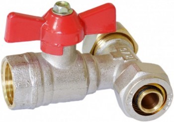
The shut-off ball valve can be installed anywhere. It is used to turn the water supply on or off. |


- If a pumping station is used, all that remains is to connect the assembled unit to it, since a pressure gauge and pressure switch come with it.
- If the pump is located in a well, then the next step is to connect a five-pin fitting through an American one. The diagram below shows what each pin does.

A fine filter or water treatment station is “placed” on the pipe leading to the hydraulic accumulator.

Advice. Before purchasing equipment and assembling it, have your water tested to see what kind of treatment it needs.
Now you can do the internal wiring.
Internal wiring
To supply water to all “consumers”, you need to buy pipes and all kinds of connecting elements. How many of them will be needed? A diagram indicating all elements of the system with distances marked on it will help answer this question.

But first you need to decide which connection method to use.
- Serial connection is easier and cheaper. But with such a connection, when several taps are turned on simultaneously, the pressure at the furthest point from the accumulator will be low.
- A collector connection involves connecting a separate line to each device. They all come out of a common manifold installed at the input. This scheme ensures equal pressure at all points of water consumption. But the cost of plumbing will be significantly higher.

The first method is only suitable for houses with a small number of consumers and a short length of water supply. The second is more practical and effective if we are talking about a private house in which a large family lives and all the necessary equipment is installed.
- After the tee, which divides the total flow into cold and hot branches, a manifold with the required number of leads is installed on the cold water pipeline. Each of them must have a shut-off valve.

- The second pipe after the tee is connected to the inlet pipe of the water heater.

- The pipe leaving the water heater is also equipped with a manifold, from which the lines diverge to individual consumers.

If you think through everything in advance and do the work carefully, the entire unit for pumping, cleaning, heating and distributing water can fit in a small area - in a corner of the room, a closet or a niche.
The following illustrations will help you better imagine how the different stages of work are performed:
Advice. To reduce pressure loss, try to make fewer turns and angles. For example, you can lay lines under the floor in a straight line from the collector to the water distribution device.
Conclusion
Schemes of water supply systems with a hydraulic accumulator will provide no less comfort in a private house than in an apartment with a centralized supply. If you know and understand the operating principle of the system, you can assemble it yourself. If you have all the necessary tools, it is not much more difficult than assembling a constructor.
For more information and the opportunity to see the process of connecting the most important nodes with your own eyes, watch the video in this article.
For continuous, high-quality work, hydraulic accumulators with submersible pumps are often used in dachas and private houses without a centralized water supply. Next we will talk about the advantages of using a hydraulic accumulator.
For recognition, hydraulic accumulators have different colors: red ones are for heating; blue - for cold and hot water supply.
A hydraulic accumulator is a metal container divided into two conventional parts by a membrane: a diaphragm or a cylinder.
Hydraulic tanks with a diaphragm membrane consist of:

Hydraulic tanks with a balloon-type membrane consist of:

Hydraulic tanks are designed for:
- cold water supply;
- hot water supply;
- heating systems.
There are horizontal and vertical hydraulic accumulators.
More often, vertical hydraulic tanks are used for country houses. They have legs, as well as a special mount on the body for hanging on the wall. They take up little space. 
Horizontal hydraulic tanks are most often used in pumping stations with external pumps. In this case, the pump is installed on the tank, which saves a lot of space.
A hydraulic accumulator with a membrane has a longer service life than a galvanized steel hydraulic tank
Is a hydraulic accumulator necessary for a submersible pump?

If the accumulator is not installed, the pump will turn on constantly as soon as the tap is opened. In this regard, the likelihood of water hammer increases. Water hammer is formed by an abrupt increase in pressure, which appears due to frequent inclusions.
Therefore, the importance of the hydraulic accumulator is obvious. The hydraulic accumulator has several names; it is called a hydraulic tank, expansion tank or membrane tank.
Normal pressure in the accumulator is from 1.4 to 2.8 atm. The pressure in the system must exceed the pressure of the tank by 0.1 atm. If you need to calculate on your own what pressure in the accumulator needs to be adjusted, then use the following formula:
Hydraulic tank pressure = (Maximum disassembly point height +6) / 10
Connection diagram for hydraulic accumulator
The water supply system includes: a pump, a hydraulic accumulator, a pressure switch, a check valve, steam fittings, a filter system, a pressure gauge, a pipeline, and, of course, electrical power.
The check valve allows water to accumulate in the hydraulic tank from the submersible pump.
Installed on the pump before connecting the entire accumulator circuit in the following sequence:
- We lower the pump into the well;
- It is necessary to secure the safety rope that holds the pump;
- We connect all the elements of the circuit using a five-pin fitting;
- It is necessary to configure the pressure switch.
Pressure switch
The pressure switch plays an important role in the operation of the accumulator, as well as the entire home system. For efficiency and correct operation of the relay, it is necessary to configure it.
To do this you need:

The water supply diagram with a submersible pump and a hydraulic accumulator, after connection, works like this:

How often your pump will turn on directly depends on the volume of the accumulator. Remember to take this into account when choosing a container.
Connection diagram for several hydraulic accumulators to a submersible pump
If, when using a hydraulic accumulator, you need another capacity to store water, then it is possible to install several more hydraulic tanks in parallel, of a suitable volume for you. 
The second and subsequent tanks are connected simply using a screwed-in tee. A pump (five-pin fitting) is connected to one input, and a new hydraulic tank is connected to the other.
When connecting several hydraulic accumulators, there is no need to reconfigure the system.
Also, the largest number of hydraulic tanks will extend the life of your pump, because... it will have to be turned on less often.
A water supply system operating in autonomous mode is a complex technical structure that requires the simultaneous use of various technical means. To automate pumping equipment and supply water to distribution points, it is necessary to install a special storage tank - a hydraulic accumulator. It is safe to say that most owners of private buildings are not familiar with this device and do not know how to install a hydraulic accumulator.
To install a hydraulic accumulator for water supply systems with your own hands, you must clearly know the rules for connecting it to the water supply system, the features of using this device and compatibility with other equipment. In addition, advice and recommendations from specialists will help avoid many problems when installing a hydraulic accumulator.
The presence of a special storage tank in the water supply system reduces the impact of water hammer on individual areas and protects household appliances.
How does a hydraulic tank work and why is it needed in a water supply system?
A hydraulic tank, membrane tank or hydraulic accumulator are the names of one device, which is a sealed metal container. Built inside it is a pear-shaped elastic membrane with a small amount of water. The membrane is attached to the hydraulic tank body using a flange with a pipe and divides the tank into two parts. One of the parts is filled with water, the second with air or nitrogen. If you plan to install a hydraulic tank in a domestic water supply system, then purchase devices filled with air. For industrial use, nitrogen is pumped into the accumulator.
As the volume of water in the container increases, the air portion correspondingly decreases, which leads to an increase in pressure in the water supply system. After reaching certain parameters, a specially configured relay sends a command to turn off the pumping equipment.
Metal is used to make the tank, but there is no reason for the formation of corrosion spots. The fact is that the metal is protected from contact with water by a membrane made of high-strength rubber butyl. This material is also highly resistant to microorganisms, which helps maintain water quality in accordance with sanitary and hygienic requirements. It is safe to say that interaction with this type of rubber does not in any way affect the taste properties of water.

Water enters the membrane compartment through a special pipe, which is equipped with a threaded connection; ideally, the pressure pipe and the connecting outlet of the pipeline have the same diameter. In this case, you don’t have to worry about additional hydraulic losses inside the pipes of the water supply system.
To regulate the pressure inside the hydraulic tank, the air chamber is equipped with a special pneumatic valve. Air is pumped into the intended compartment using a regular car nipple. Also, through this device, excess air mass is released. You can pump air using a compact car or simple bicycle pump.
The design is designed in such a way that the membrane cannot rupture under the pressure of water entering it. The fact is that the compressed air inside the hydraulic tank resists this pressure and prevents its deformation or rupture. It should be noted that compressed air allows you to adjust the pressure before connecting the accumulator.
Considering the design of a membrane tank, we can distinguish several main components:
- Housing made of metal.
- Membrane made of high-strength rubber.
- Flange equipped with valve.
- Nipple for pumping or bleeding air.
- Legs.
- Platform for installing the pump.
Knowing the design of the equipment, you can independently solve the problem of how to properly connect a hydraulic accumulator for water supply.
Operating principle of a hydraulic accumulator
At the first stage, immediately before turning on the accumulator, the air chamber occupies most of the volume of the device. When filled with water, the pear-shaped membrane increases in volume and begins to fill the inside of the hydraulic tank, thereby compressing the air. Filling continues until the pressure reaches a certain limit specified by the relay settings. After this, the relay sends a command to turn off the pump.
When the tap is turned on at the point of water collection, the system depressurizes; compressed air, exerting pressure on the membrane, promotes the release of water from the hydraulic tank. When the pressure in the system drops to the set minimum value, the relay will operate and give a command to turn on the pump. Water will again flow into the storage tank. Therefore, it is important to understand how to properly install a hydraulic accumulator in a water supply system.

The air entering the membrane compartment of the accumulator gradually accumulates, which makes the device less efficient. For this reason, it is periodically necessary to bleed air from the membrane bag. Modern models are equipped with a special valve for bleeding air. If the equipment does not have such a part, then after about 2-3 months it is necessary to carry out preventive measures in relation to the membrane tank.
Correctly solving the problem of how to connect a hydraulic accumulator in the water supply system of a private house will allow you to carry out preventive work without much difficulty, disassemble and reassemble the device if necessary, without completely draining the water from the system.
The need to install a membrane tank
Without knowing the connection diagram of the deep-well pump to the hydraulic accumulator, we can conclude that the hydraulic tank simply passes the incoming liquid through itself. However, this statement cannot be called absolutely accurate. Such a device functions as a water pressure stabilizer in the water supply system. In addition, the hydraulic tank helps to increase the operating life of the pump and protects the entire system from water hammer. In the event of a voltage drop in the electrical network, the water supply in the storage compartment will allow you not to experience problems with clean water for a certain time.
The advantages of connecting a hydraulic accumulator to a well can be described in more detail as follows:
- Protection of the pump from premature wear. The presence of a certain amount of water in the membrane tank makes it possible to satisfy the needs of residents for some time. The pump turns on only after the membrane tank is empty. Each pump has factory settings, thanks to which the device turns on and off a certain number of times within one hour. If the hydraulic accumulator is set to similar or lower values, then the service life of the pump can be increased provided that the well pump is correctly connected to the hydraulic accumulator.
- Maintaining stable water pressure values. When several taps are turned on simultaneously, a decrease in the pressure and temperature of the water in the system may occur. This situation can cause discomfort to a person who is taking a shower at this time. The presence of a hydraulic tank allows you to maintain stable water pressure values in the water supply system in a private home.
- Water hammer in most cases occurs when the pump is turned on and causes irreparable damage to pipes and other elements of the water supply system. The installed membrane tank reduces the risk of water hammer to a minimum.
- Water supplies. Most country houses have an autonomous water supply system, so water problems can arise for various reasons. For example, power outages significantly reduce the efficiency of the pump, and in some cases the device does not perform its functions at all. This situation forces you to regularly store water in an additional container. When using a scheme for connecting a hydraulic accumulator to a water supply system, this problem does not arise, since there is always a certain amount of water in the device.
Types of membrane tanks
Hydraulic tanks can be installed in water supply systems for various purposes.
In particular, we are talking about the following:
- Meeting the need for hot and cold water.
- Heating systems for a private house.
In the first case, the membrane tank allows you to extend the service life of pumping equipment due to the established on and off mode and protects the system from the destructive effects of water hammer. The second option involves using a hydraulic tank as an expander, which is built into a closed heating system and is its integral part.
According to their configuration, hydraulic tanks are divided into horizontal and vertical models. It is worth noting that the configuration of the tank does not affect the principle of its operation and the connection of the submersible pump to the accumulator.

A distinctive feature of vertical type hydraulic tanks is a special valve through which excess air is released. Moreover, in most cases, models with a volume of more than 50 liters are equipped with a valve. The valve is mounted precisely in the upper part of the container, since the air entering the membrane compartment along with water tends to accumulate at the top of the chamber.
Horizontal tanks also have a device for bleeding air, only in this case the drain device or tap is located behind the hydraulic accumulator. To remove air from a small container, drain the water completely.
When looking for an answer to the question of where to install a hydraulic accumulator for water supply systems, it is important to understand that horizontal and vertical devices are characterized by the same efficiency and functionality. Therefore, when choosing a device, first of all, the dimensions of the room where the device is planned to be installed are taken into account.
Connecting the hydraulic accumulator
The device can be mounted in different ways, this is determined by the connection diagram of the hydraulic accumulator to the water supply system, the main purpose and functions assigned to the device.
Standard device with surface pump
Most often, an autonomous water supply system for a private home requires a hydraulic accumulator and a surface pump. In this case, the manufacturer offers complex factory-assembled pumping equipment, which already includes a hydraulic tank. However, the possibility of placing the membrane tank together with the pump in a caisson or in a heated utility room is not excluded. Therefore, it is important to understand how to connect a deep-well pump to a hydraulic accumulator.

The connection diagram is most often the same. A check valve is installed in front of the hydraulic tank, eliminating the possibility of changing the water flow, followed by a pressure switch that reacts to the slightest changes in water pressure. A mandatory element in such a system is a pressure gauge, with which you can monitor the operating parameters of the entire system.
Before connecting the accumulator to the water supply system, it is necessary to additionally install an angle pipe to connect to the flange.
Installation of a booster pump
A booster pumping station is installed in places where there is active water consumption. In this case, the device constantly maintains and regulates the water pressure in the pipeline. In most cases, the pumps here operate in constant mode. If there is a need for additional pumping equipment, it is recommended to use a membrane tank that can compensate for changes in water pressure in the system.

A hydraulic accumulator included in a water supply system with a booster pumping station can act as a backup water storage device. Here you need knowledge of how to connect the expansion tank to the water supply system. In addition, a similar scheme can be used in case of unstable power supply to booster pumps in areas where uninterrupted water supply is required. In this case, the water reserves in the accumulator may well meet the needs during a power outage. In such a scheme, the membrane tank plays the role of a backup storage device. It is worth noting that powerful pumping stations require a hydraulic tank of significant volume.
Using a circuit with a submersible pump
To extend the service life of a submersible pump, it is necessary to study the question of how to connect a submersible pump to a hydraulic accumulator and select the correct on and off mode. These parameters must correspond to the technical characteristics of the device, which are specified by the manufacturer in the accompanying documentation. Normal operation of the pump is ensured when turned on 5 to 20 times within one hour.
Very often the pressure in the water supply system is below normal. In such a situation, the relay is triggered and sends a command to turn on the pumping equipment. After reaching the set parameters, the relay turns off the pump and water stops flowing.
It is worth noting another very important point when a small autonomous water supply station is not able to satisfy water needs in full. In this case, the pump will start much more often, which reduces the service life of the equipment.

Using a diagram for connecting water from a well through a hydraulic accumulator in both cases will solve the problem of rapid wear of pumping equipment. In the first option, the membrane tank will maintain pressure and regulate the water pressure in the system. In the second option, the water reserves in the membrane compartment will almost fully satisfy the needs of the residents.
When choosing the volume of a membrane tank, you need to consider the following points:
- Pump power.
- Frequency of device activation.
- Required volume of water per hour.
- The height at which the device is placed.
In closed water supply systems with a storage water heater, the hydraulic tank serves as an expander (read also: “Which scheme for connecting a water heater to a water supply system is better - installation features”). The fact is that when heated, water tends to increase in volume. The expansion of water in a closed system can have devastating effects. In this case, the hydraulic tank receives excess water, thereby saving the pipeline from ruptures.
When choosing a storage tank for such a system, it is necessary to compare the maximum water heating temperature with the declared characteristics of the installed equipment. In addition, you need to take into account the maximum water pressure values in the water supply system.
Rules for choosing a hydraulic tank
The main element of the accumulator is the membrane. Its quality characteristics determine how long the entire device will last and when the first repair will be required. The best quality membrane is made from isobutated rubber.
As for the material for making the hydraulic tank housing, this factor in most cases is not particularly important. The only exception is expansion tanks. The fact is that water flows only into the pear-shaped membrane; contact with the metal parts of the device is completely excluded.

It should be said right away that a hole in the thin walls of the flange cannot be soldered or welded. In the best case, you will have to buy a new flange, the worst case involves a complete replacement of the hydraulic tank. Such a nuisance can be prevented by choosing the correct flange thickness. A reliable membrane tank is equipped with a flange made of thick galvanized steel or stainless steel.
Features of connecting the hydraulic tank to the water supply system
A hydraulic accumulator is not just a container filled with water. This is a special-purpose device that performs a special function in the water supply system. For this reason, installing the equipment may seem quite complicated.
When solving the problem of how to connect a hydraulic accumulator to a well, it is very important to take into account vibration and noise factors. Therefore, special rubber gaskets are used for fixation on the floor, and rubber adapters are used for fastening to the pipeline. In addition, it is important to understand that the outlet diameter of the liner can be much smaller.
Fill the new tank with the utmost care, being careful not to supply water under strong pressure. If the tank is not used for a long time after manufacturing, the membrane may cake. Strong pressure or sudden supply of water can cause damage to the membrane or its complete failure. Experts recommend bleeding all the air out of the bulb before filling, which will help avoid troubles when pumping water into the accumulator.

When choosing where to install the accumulator in the water supply system, it is necessary to ensure free access to any part.
The connection of the hydraulic accumulator to the water supply system is carried out according to a certain scheme:
- A water pipe is led into the house through the foundation or basement.
- A power cable is inserted to connect pumping equipment.
- Collect individual elements in one line.
- Adjust the hydraulic tank.
- Connect the device to the general water supply system.
- If it is necessary to use two hydraulic accumulators in the water supply system, an additional device is installed in the caisson.
- Connect the pressure gauge to the second device.
- If you intend to use a water supply branch for watering plantings, then install a check valve and a drain valve.
Rules for setting up a new membrane tank
The first step in tuning is to check the internal pressure level. This value should be 1.5 atmospheres. However, it should be taken into account that leakage is possible during transportation of the device and during storage. Therefore, at the time of sale, the parameters may differ from the values specified by the manufacturer.
To record the readings, you need to remove the cap on the spool. The following types of pressure gauges are used to measure pressure:
- Electronic devices are considered the most expensive products and are quite sensitive to temperature and battery charge. This can significantly affect the accuracy of measurements.
- Mechanical or automotive pressure gauges. In most cases they have a metal body. The measuring scale may have a different number of divisions; to obtain more accurate results, it is recommended to use devices with a large number of divisions.

It is worth noting that inexpensive pumping equipment can be equipped with a pressure gauge in a plastic case; the measurement error in this case is quite large.
When deciding how to connect a hydraulic accumulator to a deep-well pump, setting the parameters of the membrane tank is of great importance for several reasons. For example, if there is insufficient pressure, water takes up most of the volume in the hydraulic tank, and as a result, the water pressure in the system decreases. High pressure provides good water pressure. However, at higher pressure values, there is less water in the hydraulic tank, which leads to frequent activation of the pump and problems with water.
When making adjustments, please note that the pressure parameters should not be less or more than the recommended values. At low pressure, the membrane may come into contact with the walls of the metal housing, which should not be allowed.
Selection of optimal air pressure parameters
When solving the problem of how to connect a submersible pump to a hydraulic accumulator, you should know that for normal operation of household appliances, it is recommended to maintain the pressure within 1.4-2.8 atmospheres. The safety of the membrane is ensured if the pressure in the water supply system is 0.1-0.2 atmospheres higher than the pressure in the membrane tank.
The pressure switch works in tandem with the hydraulic tank, so during the setup process the value is set to 1.6 atmospheres if the pressure in the system is 1.5 atmospheres.
It is worth noting that such calculations can be used when setting up equipment installed in a private one-story house. For a two-story cottage, larger values are required.
The optimal option involves using the following formula in calculations:
V = (H max + 6) / 10.
Here the letter V denotes the optimal pressure, H max is the level of location of the highest water intake point.
When performing calculations, you need to take into account the technical characteristics of the connected plumbing and household appliances. The result obtained should not be higher than the values recommended by the manufacturer. Otherwise, the equipment in the kitchen or bathroom may simply fail.
The piping of a hydraulic accumulator in a private house should include the following elements:
- Pump equipment.
- Membrane tank.
- Pressure switch.
- Reverse valve.
- Pressure gauge.
As for the last element, it is not a mandatory part of the system. The pressure gauge can be installed when performing pressure test measurements in the system.
The diagram for connecting the hydraulic accumulator to the well is as follows:
- Using one 1-inch lead, a fitting is connected to the accumulator pipe.
- A pressure gauge and a pressure switch are connected to two 0.25-inch terminals.
- Two more 1-inch leads are intended for connecting the pipe from the pump and wiring to water collection points.