Control circuit for the amount of liquid water and the pump. Automation for the pump: types of equipment and installation diagram. "Aquarius" - the best solution for home water supply
I recently came across a video on the Internet where they made my childhood dream come true. The video showed how you can assemble a device for automatically filling a container with water. All the work was very clearly demonstrated, but the diagram was not shown.
The fact is that in my childhood, in the summer, I often had to water the garden and I always had ideas for automating this process, but I never succeeded in turning my thoughts into reality. Today I will fulfill part of my dream, although only theoretically for now.
Let’s imagine this situation: you have a container of water at your dacha or at home, for watering the garden or for some other purpose. You pump water into this container using a pump. To pump water, each time you have to turn on the pump and watch until the container is filled with water. Filling a container with water can be automated very easily and quite cheaply.
Below is a structural picture of our device.

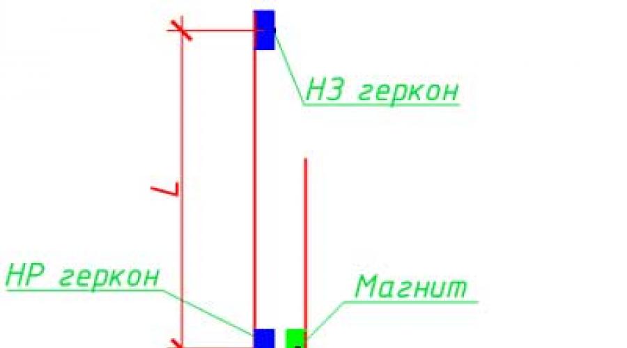
To automate filling the container with water, we will have to slightly modify the container. A rod with a height no less than the depth of the container is installed on the top of the barrel, on which two reed switches are fixed. A movable rod with a float is also attached to the rod, which moves depending on the water level in the container. A permanent magnet is attached to the rod to control the reed switches.
In the next picture you can see an example of a rod and a movable rod.

And now the most interesting part: a circuit for automatically filling the container with water.
To implement this device, we need a circuit breaker to protect the pump, an electromagnetic contactor to turn the pump on and off, and two reed switches (sealed magnetic contact) to control the contactor.

The lower reed switch should be a closing switch, the upper one should be a breaking switch. For example, the MKS-27103 reed switch is quite suitable for us, because it has a changeover contact. For low level signaling, the circuit uses a normally open contact, and for high level signaling, a normally closed reed switch contact is used. At the moment when the water level in the tank reaches a critical value, the magnet will be located at the same level with the lower reed switch, which, under the influence of a magnetic field, will switch the contact and thereby send a signal to turn on the pump. After this, the float will begin to rise to the upper level, where the upper reed switch will turn off the pump.
This scheme does not implement a manual mode, although it should be provided in case of failure of our level meters. The easiest way is to use a locking button to manually control the pump. I think it won’t be difficult for you to include a button in the resulting diagram.
Of course, you can buy ready-made level meters and not reinvent the wheel, especially since they are produced by industry. However, one such level gauge will cost you at least $30, and one MKS-27103 reed switch costs $2-3.

This is how you can automatically fill a container with water. I also had an idea for water to be drained from this container for irrigation (for example, tomatoes, cucumbers) through drainage pipes. Perhaps they do this in greenhouses.
I hope someday I will have a dacha where I can fully realize my dream, not because I like to dig in the garden, I just like others to work for me, I mean devices
When the need arises to control the fluid level, many do this work manually, but this is extremely ineffective, takes a lot of time and effort, and the consequences of oversight can be very expensive: for example, a flooded apartment or a burnt out pump. This can be easily avoided by using float water level sensors. These are devices that are simple in design and operating principle and are affordable.
At home, sensors of this type allow you to automate processes such as:
- monitoring the liquid level in the supply tank;
- pumping groundwater from the cellar;
- turning off the pump when the level in the well falls below the permissible level, and some others.
Operating principle of a float sensor
An object is placed in a liquid that does not sink in it. This could be a piece of wood or foam, hollow sealed plastic sphere or metal and much more. When the liquid level changes, this object will rise or fall with it. If the float is connected to the actuator, it will act as a water level sensor in the tank.
Equipment classification
Float sensors can independently monitor the liquid level or send a signal to the control circuit. According to this principle, they can be divided into two large groups: mechanical and electrical.
Mechanical devices
 Mechanical valves include a wide variety of float valves for the water level in the tank. The principle of their operation is that the float is connected to a lever; when the liquid level changes, the float moves up or down this lever, and it, in turn, acts on the valve, which shuts off (opens) the water supply. Such valves can be seen in toilet flush tanks. They are very convenient to use where you need to constantly add water from the central water supply system.
Mechanical sensors have a number of advantages:
- simplicity of design;
- compactness;
- safety;
- autonomy - do not require any sources of electricity;
- reliability;
- cheapness;
- ease of installation and configuration.
But these sensors have one significant drawback: they can control only one (upper) level, which depends on the installation location, and regulate it, if possible, then within very small limits. Such a valve can be sold called “float valve for containers”.
Electrical sensors
 An electric liquid level sensor (float) differs from a mechanical one in that it itself does not shut off the water. The float, moving when the amount of liquid changes, affects the electrical contacts that are included in the control circuit. Based on these signals, the automatic control system makes a decision on the need for certain actions. In the simplest case, such a sensor has a float. This float acts on the contact through which the pump is turned on.
Reed switches are most often used as contacts. A reed switch is a sealed glass bulb with contacts inside. Switching of these contacts occurs under the influence of a magnetic field. Reed switches are miniature in size and can be easily placed inside a thin tube made of non-magnetic material (plastic, aluminum). A float with a magnet moves freely along the tube under the influence of liquid, and when it approaches, the contacts are activated. This entire system is installed vertically in the tank. By changing the position of the reed switch inside the tube, you can adjust the moment the automation operates.
If you need to monitor the upper level in the tank, then the sensor is installed at the top. As soon as the level drops below the set level, the contact closes and the pump turns on. The water will begin to increase, and when the water level reaches the upper limit, the float will return to its original state and the pump will turn off. However, in practice such a scheme cannot be used. The fact is that the sensor is triggered by the slightest change in the level, after which the pump turns on, the level rises, and the pump turns off. If the water flow from the tank is less than the supply, a situation arises when the pump is constantly turned on and off, while it quickly overheats and fails.
 Therefore, water level sensors to control the pump they work differently. There are at least two contacts in the container. One is responsible for the upper level; it turns off the pump. The second determines the position of the lower level, upon reaching which the pump turns on. Thus, the number of starts is significantly reduced, which ensures reliable operation of the entire system. If the level difference is small, then it is convenient to use a tube with two reed switches inside and one float that connects them. If the difference is more than a meter, two separate sensors are used, installed at the required heights.
Despite their more complex design and the need for a control circuit, electric float sensors allow fully automated liquid level control.
If you connect light bulbs through such sensors, then they can be used to visually monitor the amount of liquid in the tank.
Homemade float switch
If you have the time and desire, then you can make a simple float water level sensor with your own hands, and the costs for it will be minimal.
Mechanical system
 In order to simplify as much as possible design, we will use a ball valve (faucet) as a locking device. The smallest valves (half-inch or smaller) work well. This type of faucet has a handle that closes it. To convert it into a sensor, you need to extend this handle with a strip of metal. The strip is attached to the handle through holes drilled in it with the appropriate screws. The cross-section of this lever should be minimal, but it should not bend under the influence of the float. Its length is about 50 cm. The float is attached to the end of this lever.
As a float you can use a two-liter plastic bottle from soda. The bottle is half filled with water.
You can check the operation of the system without installing it in the tank. To do this, install the faucet vertically and place the lever with the float in a horizontal position. If everything is done correctly, then under the influence of the mass of water in the bottles, the lever will begin to move down and take a vertical position, and the valve handle will turn with it. Now submerge the device in water. The bottle should float up and turn the valve handle.
Since valves vary in size and the amount of force required to switch them, the system may need to be adjusted. If the float cannot turn the valve, you can increase lever length or take a larger bottle.
We mount the sensor in the container at the required level in a horizontal position, while in the vertical position of the float the valve should be open, and in the horizontal position it should be closed.
Electric type sensor
For self-production of the sensor of this type, in addition to the usual tool, you will need:

The manufacturing sequence is as follows:

 When the liquid level changes, the float moves along with it, which acts on an electrical contact to control the water level in the tank. A control circuit with such a sensor may look like the one shown in the figure. Points 1, 2, 3 are the connection points for the wire that comes from our sensor. Point 2 is a common point.
Let's consider the principle of operation of a homemade device. Let's say at the moment of switching on the tank empty, the float is in the low level position (LL), this contact closes and supplies power to the relay (P).
The relay operates and closes contacts P1 and P2. P1 is a self-locking contact. It is needed so that the relay does not turn off (the pump continues to work) when the water begins to rise and the contact of the low pressure unit opens. Contact P2 connects the pump (H) to the power source.
When the level rises to the upper value, the reed switch will operate and open its contact VU. The relay will be de-energized, it will open its contacts P1 and P2, and the pump will turn off.
 As the amount of water in the tank decreases, the float will begin to fall, but until it takes the lower position and closes the NU contact, the pump will not turn on. When this happens, the work cycle will repeat again.
This is how a water level control float switch works.
During operation, it is necessary to periodically clean the pipe and float from dirt. Reed switches can withstand a huge number of switchings, so this sensor will last for many years.
Owners of individual buildings erect wells or artesian wells near their homes, which provide them with water.
A few decades ago it was carried in buckets. However, we live in a time when automation has become accessible to the common man.
It can significantly facilitate heavy physical labor and free up time for productive intellectual activity.
The published article contains advice for a home craftsman on making a simple automatic water pump control based on the available K561LA7 microcircuit. It copes well with the water supply of a private home. It is easy to make it yourself. The presented material is supplemented by explanatory pictures, diagrams and a video.
Chip K561LA7 as the main logic element
Its production was widely established during the Soviet era. The design was made of a plastic case with two rows of fourteen pins: 7 pieces on each side.

The control logic of the CMOS structure microcircuit is based on four identical elements with two inputs operating on the “AND-NOT” principle.
How to make an automatic pumping station
The article discusses the issue when the water supply of a house is already organized, that is, there is a well with water and an electric pump is mounted in it, capable of creating the necessary pressure for raising water.
All we have to do is plan its control circuit in automatic mode and install it as a separate unit. This will require a small set of electronic parts.
Basic principles of operation of the power unit
The pump can be controlled in two ways:
- in manual mode;
- automatically.
Power connection features
The proposed machine provides for the manufacture of an automation unit in the form of a separate housing, connected to the power supply circuit of the manual mode power circuit.

This means that a regular water pump, for example, the budget “Rucheek” model, is put into operation after the plug of its power cord is inserted into the socket and voltage is applied to it by turning on.
The automation unit also has a power cord with a plug and an output socket from which voltage will be supplied to the pump. This allows you to switch the circuit to manual operation at any time in order to carry out maintenance or repair of the control circuit.
How is the water level controlled?
The logical part of the automation chip constantly scans the state of the sensors. They are made of simple metal electrodes in the form of wire rods with an insulation layer for NP and VP (it is removed at the bottom), and for OP - bare metal: stainless steel or aluminum. They are located at different levels.

The lower position of the water in the tank is assessed by the NP sensor, and the upper position by the VP sensor. The common electrode of the OP is located so that it covers the entire controlled area of work.
This placement allows the machine’s logic chip to determine the presence of water in the tank by the passage of currents created by applied potentials to the electrodes through the liquid. Due to this, the level is judged:
- upper - when currents flow between NP-OP and VP-OP;
- average - current is available only in the NP-OP circuit;
- lower - there is no current anywhere.
Features of block mounting
I put together a similar circuit for my neighbor's garage. He has a pit there for storing vegetables. The location near the mountain turned out to be not entirely successful. In the spring when the snow melts, in the summer and autumn when it rains, water can flood the basement and he has to pump it out.
The assembled automation circuit made it much easier to control the pump. It is mounted in a housing from an old electronic unit with the possibility of installation on a table, rack or stationary mount on the wall. The owner simply placed the device on a shelf located at a two-meter height and connected it to the network.
The automation operated successfully for two years. Then the owner accidentally touched the case and dropped the device onto the concrete floor. A short circuit occurred inside the unit, the step-down transformer and the K561LA7 microcircuit burned out.
Install the automation system and secure it securely. Immediately eliminate the possibility of accidental fall and damage to the equipment by any means. Pay attention to.
Electronic circuit
To implement it, the K561LA7 microcircuit is used. Chains are created for it:
- nutrition;
- monitoring water levels with sensors;
- LED indication;
- switching device control.

Power scheme
Let's pay attention to:
- transformer;
- diode bridge;
- Voltage regulator.
Transformer
To power the electronics, you will need a 220/10-15 volt step-down transformer with a current of 60 mA or higher. You can wind it yourself using the method described by me,” or you can take it from an old TVK110L tube TV. Also, such models are not difficult to buy online in China or another country.
Diode bridge
The choice of KTs405E with a permissible rectification current of 1000 mA in the diagram is given as an example. It is quite possible to get by with a bridge with reduced ratings or solder a diode assembly from other available semiconductors with lower power. The K561LA7 microcircuit and the control circuits connected to it do not create large loads.
Voltage regulator
The KREN8B semiconductor assembly is designed to stabilize the 12-volt power supply of a logic chip. It is produced in a single package and is widely used in radio-electronic devices.

It is quite possible to replace it with a homemade stabilized power supply using bipolar transistors, but I don’t see much point in dealing with this issue.
Water level control circuit
Connection method
The electrode sensors are connected to the inputs of the logic chip using wires. To lay them, it is convenient to mount two chains:
- internal in the body of the automation unit;
- external to the electrodes.
To connect them, a terminal block of any available design is installed on the device body. In the external circuit, it is necessary to properly insulate the wires, protect the soldering points from moisture and corrosion.

Pumping water from the tank
The position of jumper J1, highlighted in brown on the electronic circuit of the automation, determines the pumping logic of the pumping station. We put it in position 1-2.
I will not fully describe the operation of the electronics, but I will answer any questions that arise in the comments. I’ll just briefly point out that when the water level is above the upper position, the logic sends a signal to pump, and the pump will work until it removes the water so that it dries, breaking the circuit between the lower and common sensors.
When the water fills the tank again, reaching the upper level, the pump will automatically repeat the cycle just described.
Pumping water into the tank
Jumper J1 is set to position 2-3. The pump works to fill the container from dry to the upper level and stops pumping there. When the container is drained, the cycle resumes.
The power circuit for connecting the pressure and drain lines of the pump must correspond to the selected control mode and the position of jumper J1 in the automation unit.
LED display circuit
Any LEDs can be mounted, but those chosen with a brighter glow will be more noticeable.
The lighting of LED HL1 indicates that voltage is supplied to the pump, that is, that it is turned on, and LED HL2 indicates that the power supply circuit of the entire unit is on.
Power output contact control circuit
Optocoupler U1 provides galvanic isolation of control circuits, water and triac VS1, which supplies 220 volts to the pump. The technical characteristics of the KU208G provide control of electric motors with a power of up to two kilowatts, which is usually sufficient for domestic purposes.
Options for changing the power stage
To connect more powerful electric motors, you will need to use triacs that can withstand increased loads.
An alternative solution to the circuit is to abandon the triac and use a relay or magnetic starter. For this purpose, it is necessary to replace the transistor switch VT1 with a more powerful one. For example, it is permissible to assemble a composite transistor from two: KT315 + KT815 or their analogues. For such a connection, a Darlington circuit is used.

It will control the relay winding and supply voltage to it.
The output contact of the relay will pass through the load current of the pump motor. To increase its performance, it is recommended to connect all free contacts in parallel and ensure their simultaneous operation.
When using a relay or starter in the power supply circuit, it is necessary to clarify the power of the power supply and the characteristics of the step-down transformer: it may have to be replaced with a reinforced model.
It is worth noting that the pump automation circuit assembled using any of the options works immediately without the need for complex setup. The main condition: to eliminate errors during its installation. It is permissible to assemble the automation unit using the hinged method. But it is better to use a printed circuit board.
Automation of pumping units makes it possible to increase the reliability and continuity of water supply, reduce labor and operating costs, and reduce the size of control tanks.
To automate pumping units, in addition to general-purpose equipment (switches, intermediate relays), special control and monitoring devices are used, for example, relays for monitoring the filling of centrifugal pumps, jet relays, float relays, electrode level relays, various pressure gauges, capacitive-type sensors, etc.
A complete device up to 1 kV, designed for remote control of electrical installations or their parts with automated performance of control, regulation, protection and alarm functions. Structurally, the control station is a block, panel, cabinet, panel.
The control unit is a control station, all elements of which are mounted on a separate plate or frame.
Control Panel- a control station, all elements of which are mounted on panels, slats or other structural elements assembled on a common frame or metal sheet.
Control panel (shield of control stations control panel)- This is an assembly of several panels or blocks on a three-dimensional frame.
A control cabinet is a control station protected on all sides in such a way that when doors and covers are closed, access to live parts is prevented.

Automation of pumps and pumping stations, as a rule, comes down to controlling a submersible electric pump based on the water level in the tank or pressure in the pressure pipeline.
Let's look at examples of automation of pumping units.
In Fig. 1, but shown automation diagram of a simple pumping unit- drainage pump 1, and in Fig. 1, b shows the electrical diagram of this installation. Automation of the pumping unit is carried out using a float level switch. The KU control key has two positions: for manual and automatic control.
Rice. 1. Design of the drainage pumping unit (a) and its electrical automation circuit (b)
In Fig. 2 is given automation scheme for controlling a submersible pump based on the water level in the tank of a water tower, implemented using relay contact elements.
Rice. 2. Schematic diagram of automation of a submersible pump based on the water level in the tank-water tower
The operating mode of the pump automation circuit is set by switch S A1. When you set it to position “A” and turn on the QF circuit breaker, voltage is supplied to the electrical control circuit. If the water level in the pressure tank is below the low level electrode of the remote control sensor, then contacts SL 1 and SL 2 in the circuit are open, relay KV 1 is de-energized and its contacts in the coil circuit of the magnetic starter KM are closed. In this case, the magnetic starter will turn on the pump motor, at the same time the HL 1 signal lamp will go out and the HL 2 lamp will light up. The pump will supply water to the pressure tank.
When water fills the space between the lower level electrode SL 2 and the sensor body connected to the neutral wire, the SL 2 circuit will close, but relay K V1 will not turn on, since its contacts, connected in series with SL 2, are open.
When the water reaches the upper level electrode, the SL 1 circuit will close, the KV 1 relay will turn on and, opening its contacts in the coil circuit of the KM magnetic starter, will turn off the latter, and by closing the closing contacts, it will become self-powered through the SL 2 sensor circuit. The pump motor will turn off and go out the HL 2 signal lamp and the HL 1 lamp will light up. The pump motor will restart when the water level drops to a position where the SL 2 circuit is open and the KV 1 relay is turned off.
Turning on the pump in any mode is possible only if the circuit of the “dry running” sensor DSH (SL 3), which controls the water level in the well, is closed.
The main disadvantage of level control is the susceptibility of level sensor electrodes to freezing in winter, which is why the pump does not turn off and water overflows from the tank. There are cases of destruction of water towers due to the freezing of a large mass of ice on their surface.
When controlling the operation of the pump by pressure, an electric contact pressure gauge or pressure switch can be mounted on the pressure pipeline in the pump room. This makes it easier to maintain the sensors and eliminates exposure to low temperatures.
In Fig. 3 is given electrical circuit diagram for controlling a tower water supply (pumping) installation using signals from an electrical contact pressure gauge (pressure).
Rice. 3. Schematic diagram of the control of a tower water supply installation from an electric contact pressure gauge
If there is no water in the tank, the pressure gauge contact S P1 (lower level) is closed, and contact S P2 (upper level) is open. Relay KV1 is activated, closing contacts KV1.1 and KV1.2, as a result of which the magnetic starter KM is turned on, which connects the electric pump to a three-phase network (the power circuits are not shown in the diagram).
The pump supplies water to the tank, the pressure increases until the contact of the pressure gauge S P2, set to the upper water level, closes. After contact S P2 is closed, relay KV 2 is activated, which opens contacts KV 2.2 in the relay coil circuit KV1 and KV2.1 in the coil circuit of the magnetic starter KM; the pump motor is switched off.
When water flows from the tank, the pressure decreases, S P2 opens, turning off KV 2, but the pump does not turn on, since the pressure gauge contact S P1 is open and the relay coil KV1 is de-energized. Thus, the pump is turned on when the water level in the tank drops before the pressure gauge contact S P1 closes.
The control circuits are powered through a 12 V step-down transformer, which increases the safety of servicing the control circuit and electrical contact pressure gauge.
To ensure operation of the pump in the event of a malfunction of the electrical contact pressure gauge or control circuit, toggle switch S A1 is used. When it is turned on, the control contacts KV1.2, KV2.1 are bypassed and the coil of the magnetic starter KM is directly connected to a 380 V network.
In the L1 phase break, the control circuit includes a ROF contact (phase failure relay), which opens when the supply network is in open-phase or asymmetrical mode. In this case, the circuit of the KM coil is broken and the pump is automatically turned off until the damage is repaired.
Protection of power circuits in this circuit from overloads and short circuits is carried out by an automatic switch.
In Fig. 4 is given automation diagram of a water pumping installation, which contains an electric pump unit 7 of a submersible type located in well 6. A check valve 5 and a flow meter 4 are installed in the pressure pipeline.
The pumping unit has a pressure tank 1 (water tower or air-water boiler) and (or levels) 2, 3, with sensor 2 responding to the upper pressure (level) in the tank, and sensor 3 to the lower pressure (level) in the tank. The pumping station is controlled by control unit 8.
Rice. 4. Automation diagram of a water pumping installation with a variable-frequency electric drive
The pumping unit is controlled as follows. Let us assume that the pumping unit is switched off and the pressure in the pressure tank decreases and becomes below Pmin. In this case, a signal is received from the sensor to turn on the electric pump unit. It is started by smoothly increasing the frequency f of the current supplying the electric motor of the pumping unit.
When the rotation speed of the pump unit reaches the set value, the pump will enter operating mode. By programming the operating mode, you can ensure the desired intensity of the pump run-up, its smooth start and stop.
The use of an adjustable electric drive of a submersible pump makes it possible to implement direct-flow water supply systems with automatic maintenance of pressure in the water supply network.
The control station, which provides smooth start and stop of the electric pump and automatic maintenance of pressure in the pipeline, contains a frequency converter A1, a pressure sensor BP1, an electronic relay A2, a control circuit and auxiliary elements that increase the reliability of electronic equipment (Fig. 5).
The pump control circuit and frequency converter provide the following functions:
Smooth start and braking of the pump;
Automatic level or pressure control;
Dry running protection;
Automatic shutdown of the electric pump in case of open-phase operation, unacceptable voltage drop, or in case of an accident in the water supply network;
Overvoltage protection at the input of frequency converter A1;
Alarm about turning the pump on and off, as well as about emergency modes;
Heating of the control cabinet at subzero temperatures in the pump room.
Smooth start and smooth braking of the pump is carried out using an A1 frequency converter of type FR -E-5.5k-540EC.
Rice. 5. Schematic diagram of automation of a submersible pump with a soft start device and automatic pressure maintenance
The electric motor of the submersible pump is connected to the U, V and W terminals of the frequency converter. When you press the S B2 “Start” button, relay K1 is activated, contact K1.1 of which connects the STF and PC inputs of the frequency converter, ensuring a smooth start of the electric pump according to the program specified when setting up the frequency converter.
In the event of a failure of the frequency converter or the pump motor circuits, the A-C circuit of the converter closes, ensuring the activation of relay K2. After K2 is triggered, its contacts K2.1, K2.2 close, and contact K2.1 in circuit K1 opens. The output of the frequency converter and relay K2 are turned off. Restarting the circuit is possible only after eliminating the fault and resetting the protection with the 8B3.1 button.
The BP1 pressure sensor with an analog output of 4...20 mA is connected to the analog input of the frequency converter (pins 4, 5), providing negative feedback in the pressure stabilization system.
The functioning of the stabilization system is ensured by the PID controller of the frequency converter. The required pressure is set by potentiometer K1 or from the frequency converter control panel. When the pump is “dry running”, contact 7-8 of the electronic resistance relay A2 is closed in the short-circuit relay coil circuit, to which contacts 3-4 the “dry running” sensor is connected.
After the short-circuit relay is triggered, its contacts K3.1 and KZ.2 are closed, as a result of which the protection relay K2 is activated, ensuring that the pump motor is turned off. The short-circuit relay becomes self-powered through contact K3.1.
In all emergency modes, the HL1 lamp lights up; The HL2 lamp lights up when the water level drops into an unacceptable state (when the pump is “dry running”). Heating of the control cabinet in the cold season is carried out using electric heaters EK1...EK4, which are turned on by the contactor KM1 when the thermal relay VK1 is activated. Protection of the input circuits of the frequency converter from short circuits and overloads is carried out by the QF1 circuit breaker.
The article uses materials from the book by Daineko V.A. Electrical equipment of agricultural enterprises.
Pumping units used to normalize the water supply have a certain warranty period, but to extend it, it is advisable to use automatic control of the water pump. Such equipment is an installation that prevents damage to the injection device when the water level in the source is insufficient.
If a pumping substation operates without an appropriate sensor, the risk of its failure increases, since it is not designed to operate “dry”. When there is a shortage of fluid, equipment begins to deteriorate and burn out. If you install a water level sensor, you can prevent such troubles. This article is devoted to solving the issue of choosing a protective device, its operating principle and features.
Selecting a relay to protect the pumping station from idling and maintaining the optimal water level at home requires no less attention than. First of all, you should take into account the characteristics of your own well, and also use indirect advice:
- installation should be convenient and accessible. Therefore, you should not purchase too massive installations. They must also correspond to the characteristics of the pump itself;
- It is ideal if your sensor has simplified automatic adjustment. In other words, the device has the ability to independently disconnect from the network until the water in the well returns to its previous level;
- Make sure that the protective relay is well waterproofed, since moisture entering the housing will damage the mechanism if the liquid level increases;
- Check with the seller to see how durable and reliable the pump part is. It wouldn’t hurt to find out how frequent loss of water level in a well affects the operation of the protection;
- the price must correspond to optimal parameters regardless of the manufacturer. Cost may vary due to different pressure ranges and general technical characteristics.
Important! If you made the right choice and installation, the relay will be able to independently stop the device without harm to the working mechanism of the pumping equipment.
Working mechanism of the sensor. How does the design behave when turned on?
A typical idle speed switch for a pump is set to operate at a pressure in the range from 1 to 8 bar, and is oriented according to the liquid level. The internal mechanism of the sensor is a unit with tuned springs that are responsible for two-way pressure limits. They are adjusted with specially installed nuts. The pressure indicator is controlled by a membrane plate, with the help of which the spring is weakened at minimum pressure and tightened when the maximum value is reached.

The pressure sensor spring is activated when the circuit contacts open and close. If the pressure drops, the contacts close, which is carried out by the protection sensor and the pump comes into working position. Otherwise, the pump turns off and does not operate until the pressure normalizes to optimal levels.
To configure the correct operation of the sensor, you will need a pump control circuit. In order to fine-tune it, it is necessary to bring the pumping unit into working condition - this will increase the water pressure in the well. The operation of the installation can be adjusted using specially located screws under the cover, which protects the sensor automation.
You can independently set the operating limits of the protective device. To do this, perform the following steps sequentially.

- We fix the maximum and minimum pressure limits based on the liquid level in the container at which the pump is in operating condition. Be sure to take readings from the pressure gauge.
- We disconnect the pumping unit from electricity and disassemble the protective device.
- Remove the housing cover and slightly loosen the nut holding the small spring.
- Then we set the minimum pressure: we tighten or release the large spring, also using the locking nut.
- We open the tap to reduce the pressure in the pipeline system. At the same time, do not forget to monitor the operation of the pump.
- We pay attention to the readings of the pressure gauge, if they are optimal for your case, we leave the relay in this state, if not, we adjust it further.
Attention! When setting up the idle speed control sensor, you must take into account the capabilities of the pumping unit. For example, if its factory value with losses is about 3.5 bar, the relay needs to be set to 3 bar. Otherwise, there is a risk of equipment overload.
A few words about automatic water pump control
Devices based on the “automatic” circuit can be useful at home and on the farm. The presence of such equipment is especially important in systems where control of water level and pressure is required.
Sensors based on an automatic control circuit are considered useful and do not require constant monitoring of the equipment of a well, well or other source of water supply. Also, such designs are often used multifunctionally.
Pay attention to the automatic pump control circuit; it is in no way connected with the common reservoir from where water flows through the pump.