Wiring diagram in an apartment with a pen conductor. Separation of PEN into PE and N. Power connection in old houses
The power supply of a house or apartment electrical network is carried out by a single-phase (less often three-phase) electric current of 220 V. The voltage is distributed to consumers using a three-phase network through four wires, one of which is zero. Single-phase power means that one out of three phases and a neutral wire, common to all consumers, come to the end consumer (house, apartment). With a uniform load, the current in the neutral wire is present only at consumers. After combining all the wires into a three-phase circuit, there is no current in the neutral wire. We will tell in the article how the PEN conductor is divided into pe b and n.
Power connection in old houses
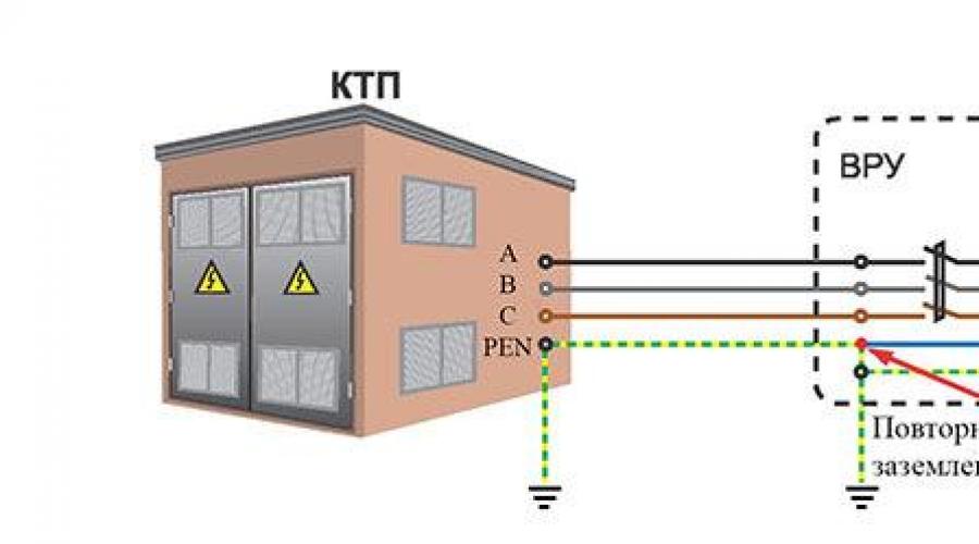
According to the old standards, a ground loop was made at the supply transformer substation, which was connected to the neutral wire (such a connection is called zeroing). A wire connected to the ground loop and suitable for consumers is called a PEN conductor. It simultaneously performs the functions of a worker (by mute, the current returns to the substation) and a protective conductor.
Such a power system is called TN-C and is still used in old houses.Sockets in apartments with TN-C do not have ground terminals. To protect consumers from electric shock during phase closures to the case inside the equipment, the neutral conductor is connected to the ground terminal of the device, that is, grounding is performed.
There is a danger of electric shock if the neutral conductor breaks between the consumer and the supply substation. To increase safety, an additional ground loop is installed near the house and connected to the neutral conductor already on the consumer side.
Alteration of the old TN-C power system to match the TN-C-S system
 The PE conductor is additionally connected to the grounding device of the house (re-grounding is performed).
 In order to transfer the power system to a more advanced TN-C-S, the PEN conductor is divided into PE - protective and N - neutral. According to its principle, the TN-C-S system consists in the fact that the PEN conductor suitable for the house on the input-distribution device (ASU) is divided into two separate ones and in this form it approaches the end user.

The design of the sockets is such that when turned on, the ground terminals are closed first, and only then the terminals with phase and neutral conductors. Neutral (neutral conductor serves to transfer electrical energy to the consumer, and protective to ensure safety.
Organization of the TN-C-S system in accordance with the Electrical Installation Rules (PUE)
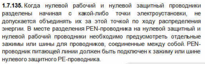
Paragraph 1,7,135 of the PUE specifies exactly how to correctly divide the PEN conductor into separate and independent PE and N. To do this, at the point of separation (splitting) of the PEN conductor, separate buses or terminal blocks are provided for connecting PE and N conductors. Separated busbars are interconnected with a jumper. The input PEN conductor of the power supply line is connected to the PE busbar of the conductor.
Important! It is not allowed to recombine the PE and N conductors beyond the separation point. The rules for the installation of electrical installations (clauses 1, 7, 145) prohibit the installation of any switching devices and devices in the circuits of PE and PEN conductors. The insulation of PEN, PE and N conductors must be the same as that of the phase conductors, and their cross section must be determined from the table:
Input-distribution device (ASU)

It is in the ASU that the PEN conductor is divided into PE and N. To do this, it provides separate PE and N buses, which are interconnected by a jumper. PE and N busbars are made of copper, in extreme cases, aluminum.
Important! It is impossible to fasten copper wires directly to the aluminum bus in order to avoid the appearance of an electrochemical couple. It is necessary to use steel washers that are laid between the bus and the copper core. Aluminum wires are also attached to the copper bus.
Tires should be connected from both edges or in the middle with jumpers with a cross section not less than the tires. Bolted connection only. The PE busbar is attached directly to the base, and the N busbar is attached through dielectric (insulating) gaskets.

When installing wiring in the input shield, the recommended color of the wires should be observed. This will help avoid confusion and accidents in the future. The following wire colors are accepted:
- Phase A (L1) - yellow;
- Phase B (L2) - green;
- Phase C (L3) - red;
- Neutral wire (N) - blue;
- Protective wire (PE) - yellow-green.
Reliable grounding of the PE conductor at the ASU
To install a ground loop, you need three pins made of rolled steel with a diameter of at least 16 mm and a length of 3 m. They are hammered into the corners of an equilateral triangle into a pre-dug trench 30-50 cm deep. The sides of the triangle should be 2.5 - 3 m. The upper ends of the pins are welded between a steel strip measuring 4x30 mm.

Tip #1 The distance from the ground loop to the wall of the building should be from 1 to 6 m.
Instead of rolled steel, it is allowed to use a pipe with a diameter of at least an inch and a quarter with a wall thickness of 3.5 mm or a steel corner 50x50 mm. To facilitate driving, the ends of the pins must be sharpened with an improvised tool. Welding points and the connecting bar must be well painted over to protect against corrosion. Important! Ground pins must not be painted!
A conductor made of steel or copper is laid from the circuit to the PE bus. The cross section of the Steel conductor must be at least 100 mm2, and that of the copper conductor must correspond to the cross section of the PE conductor or more. After the installation of the ground loop by the power supply organization, it is necessary to measure the spreading resistance of the ground loop. It should be no more than 10 ohms when powered by a three-phase current with a linear voltage of 380 V (phase voltage - (220 V).
Errors when dividing the PEN conductor into PE and N
The most common mistake when laying PE and N conductors separately is to merge them behind the separation point. In the normal state of the equipment, no current should flow through the PE conductor, and as a result of the combination, it begins to work as a working zero (neutral conductor). As a result - incorrect operation of residual current devices (RCD). A common mistake is to install jumpers between zero and the ground contact (PE) of the outlet. The most severe consequences of such a combination arise in the event of a break in the neutral conductor to the connection point in the outlet.
The second mistake is the implementation of separate ground loops for various devices in the same building. In this case, a potential difference arises at the different ends of the PE conductor, which will lead to the flow of current in the PE conductor. If the PE between devices is interrupted, electric shock may result. Also, such a connection may cause malfunctions of digital equipment.
The third mistake is the use of a building fittings conductor or water pipes as a grounding conductor PE. Home fittings do not guarantee reliable contact with the ground, and plumbing may have places damaged by corrosion or non-conductive plastic inserts. If PE grounding is made to the water supply in several apartments, then a situation may arise as in the second error.
Tip #2 According to paragraphs 1, 7, 61. PUE for grounding the PE conductor at the input to the building, it is recommended to use natural ground electrodes.
FAQ
Question number 1. Why is so much attention paid to the issue of colored wires?
Painting does not affect the operation in any way, but makes it easier to work during repairs or changes to the installation. Especially if different people do it.
Question number 2. Why is it impossible to install switching devices in the PE circuit of the conductor?
When the phase wire is closed in the device, on its case, in the event of a break in the PE conductor, there will be a life-threatening potential.
Question number 3. Why can't you paint the ground rods, because painting protects against corrosion?
In addition to protecting against corrosion, the paint layer acts as an insulator, negating the protective properties of the ground.
Question number 4. What is the danger of connecting copper and aluminum wires?
The combination of copper and aluminum forms an electrochemical pair (similar to the structure of salt batteries). As a result, intense corrosion of conductor materials begins with the formation of a non-conductive layer of oxides.
The FORUMHOUSE website published an article " Construction of grounding systems: diagrams, parameters, materials used and additional equipment - theory and practice from FORUMHOUSE users» (see https://www.forumhouse.ru/articles/engineering-systems/7266). The article contains incorrect information about the types of system grounding (see) and their application, the separation of the PEN conductor, the implementation of grounding devices. Consider some of the mistakes made in the information about the separation of the PEN conductor.
The article says: " It's about dividing the incoming neutral wire, which leads to consumer in TN-C systems and separated when creating the TN-C-S system. A similar division is shown in the diagram.
TN-C-S system design
».
We read further: " Separation of the PEN conductor is carried out according to the following scheme:
For separation, two tires should be used: main grounding (GZSH) and zero(N). The main ground bus is connected to an additional ground circuit through the shield body, while the PEN input cable is connected to it and the ground terminals of the sockets installed in the house are connected. The following are connected to the N bus: an electric meter, circuit breakers and power terminals of home energy consumption points.
The main ground bus becomes the PE bus after the jumper connecting the GZSH and N. It is to PE that an additional ground circuit and protective conductors are connected leading to the ground terminals of the sockets».
The quoted information contains errors. Firstly, the vague phrases “neutral wire”, “zero bus”, “TN-C-S system design”, “PEN input cable”, “power terminals of home energy consumption points”, as well as the jargon “grounding loop”, “grounding socket terminal", "protective circuit breaker".
Second, the term main ground bus» defined in clause 20.5 GOST 30331.1(see and) as follows: "A busbar that is part of the grounding device of an electrical installation and is intended for the electrical connection of conductors to a grounding device." Connect to the main ground bus:
grounding conductor, through which the GZSH is connected to the ground electrode (see);
potential equalization conductors used in the building;
protective conductor, through which the protective busbar of the input-distribution device (ASU) is connected to the GZSH.
Thirdly, according to the requirements GOST R 50571.5.54(see) The PEN conductor should be connected to the PEN bus (clamp) or protective bus (clamp), which is usually installed in the ASU. On this bus (clamp), the PEN conductor is divided into protective and neutral conductors. The ASU protective bus is connected to the GZSH. Separation of the PEN conductor at the input terminal of the ASU, see.
Conclusion. The information on the separation of the PEN conductor set out in this article does not meet the requirements of GOST 30331.1 and GOST R 50571.5.54. Therefore, it misleads ordinary people who are trying to get correct information on FORUMHOUSE. Guided by such articles, it is impossible to create safe electrical installations of buildings.
PEN conductor is a combined zero working (N) and zero protective (PE) conductors in electrical installations with voltage up to 1 kV with a solidly grounded neutral.
It is not allowed to connect zero working - N and zero protective - PE conductors under one terminal clamp, in order to maintain the connection of the protective conductor to ground in case of burnout (destruction) of the terminal contacts.
It is forbidden to combine the zero protective and zero working conductors after separating the PEN conductor at the entrance to the building.
The cross section of the PEN conductor must be at least 10 mm 2 for copper or 16 mm 2 for aluminum.
It is forbidden to install switching contact and non-contact elements in the circuits of PE and PEN conductors. Only connectors and connections specially designed for this purpose and which can be disassembled with a tool are allowed.
PEN conductor.
/5.3./ In stationary electrical installations of three-phase current, the function of the protective and neutral working wires can be combined in one conductor (PEN-conductor), provided that the following requirements are met:
- if its cross section is at least 10 mm 2 for copper or 16 mm 2 for aluminum and the part of the electrical installation in question is not protected by residual current devices that respond to differential currents;
- if, starting from any installation point, the zero working and zero protective conductors are separated, it is forbidden to combine them beyond this point. At the separation point, it is necessary to provide separate clamps or busbars for the zero working and zero protective conductors.
The PEN conductor, which combines the functions of a working and protective conductor, must be connected to a terminal designed for a protective conductor.
/5.4./ Third-party conductive parts cannot be used as the only PEN conductor.
/5.5./ It is allowed to install switches in the PEN conductor circuit, which, simultaneously with disconnecting the PEN conductor, disconnect all live conductors.
/5.6./ It is allowed to use PEN conductors of lighting lines for neutralizing electrical equipment powered by other lines, if all these lines are fed from one transformer, their conductivity meets the requirements of this chapter and it is impossible to disconnect PEN conductors during operation of other lines. In such cases, switches that disconnect PEN conductors together with phase conductors should not be used.
/5.7./ In places where bare PE and PEN conductors can form electric pairs or damage to the insulation of phase conductors is possible as a result of sparking between bare PE or PEN conductor and exposed conductive parts (OPC) or third-party conductive parts (SF) , for example, when laying wires in pipes, boxes, trays, PE and PEN conductors must have insulation equivalent to that of the phase conductors.
/5.8./ It is not allowed to use PEN conductors in the power supply circuits of single-phase current consumers. To power such electrical receivers, a separate third conductor must be used as a neutral working conductor (N-conductor), connected to the PEN conductor in a junction box, a low-voltage complete device.
Hello, dear readers and visitors of the site.
Today I decided to tell you about where and how to correctly divide the PEN conductor into PE and N. This idea was prompted by endless disputes and discussions on thematic forums.
In this article, referring to the paragraphs of the current regulatory documents (PUE, PTEEP, various GOSTs), I will try to give you the final correct and exhaustive answer to this question.
First, let's decide why we need to separate the PEN conductor. To do this, let's turn to the last one, clause 7.1.13, where it is said that:

This means that all electrical installations with a voltage of 380/220 (V) must have a TN-S grounding system, or, in extreme cases, TN-C-S. And what to do when we in Russia are still made according to outdated standards with the TN-C grounding system.

Thus, during any reconstruction (change) or modernization of the electrical installation, and also if you are not indifferent, you need to switch from the TN-C grounding system to more modern TN-S or TN-C-S, but at the same time it is necessary to divide the PEN conductor into zero working N and zero protective PE, and moreover, correctly. This is where confusion and constant disagreement begin.
I will give an example of the access shield of one of the residential buildings where we spent - horror:

In this article, I will not focus on grounding systems, because. I wrote about each separately, pointing out their advantages and disadvantages. Read:
So, let's move on to the issue of dividing the PEN conductor into zero working N and zero protective PE.
How to split a PEN conductor into PE and N?
To better represent what is written below, I will give examples from my practice with real photographs. As an example, consider the power supply of an apartment building, such as "Khrushchev".
PUE, clause 1.7.135:

I explain: from the place where the PEN conductor is divided into zero working N and zero protective PE, their further connection (unification) is prohibited.
At the place of separation, in our example it is VRU-0.4 (kV), two tires (or clamps) are installed, which must be interconnected and marked:
- the PE bus or it is also called the GZSH (I wrote about it in more detail in the article about)
- tire N

Any wire or bar of the same section and material can serve as a jumper. Some of mine install two jumpers at the edges of these tires, which, in principle, does not contradict the requirements of the PUE.
I emphasize that the busbars or clamps must have separate connection points for the corresponding PE and N conductors, and not be connected in one place for one bolt or clamp.
The N bus is mounted on special insulators, and the PE bus (GZSH) is fixed directly to the VRU-0.4 (kV) case.

We read the PUE, clause 1.7.61:

And now we need to re-ground the PE bus (GZSH), to which the PEN conductor of the input cable is connected. The above paragraph says that natural grounding conductors can be used as re-grounding. I recommend that you install a grounding device, in short - Z.U. You can read about how you can do it yourself in my article about.
After installing the grounding device (Z.U.) it is necessary. This will help you in the place of residence.
If the resistance of the mounted grounding device meets the requirements of PTEEP and PUE, then we connect the PE (GZSH) bus with our grounding device using a grounding conductor. Well, that's all, from this point of the electrical installation, the introductory PEN conductor is divided into zero working N and zero protective PE conductors.
PEN conductor separation schemes
I will give an example of a three-phase input scheme with to the network:

The layout of the above circuit may vary slightly. For example, instead of an introductory machine, a three-pole knife switch can be installed, and introductory fuses and are installed after the counter. Similarly, fuses can be installed instead.
Let's move on to a good example: a residential multi-apartment 4-storey building is powered by a transformer substation (TS), located in the yard, with an AVBbShv cable (4x70).


The introductory cable of the AVBbShv 2 (3x70) brand is laid to the ASU with two threads.

Three cable cores are phase conductors (A, B, C) connected to the input three-pole switch. As a PEN conductor, the metal sheath of the input cable is used, which is connected directly to the PE bus (GZSH).


After the introductory knife switch, introductory fuses PPN-35 with a nominal value of 250 (A) and a transformation ratio of 200/5 are installed. To protect against group loads, in our example, this is the main electrical wiring (risers) of entrances, PPN-33 fuses with a rating of 50 (A) are used.

Here is an example of a single-phase input circuit for a private house or cottage, powered by a two-wire with further separation of the PEN conductor in the input shield:

Here I want to add that the introductory machine must be installed in a plastic box so that it can be sealed, otherwise problems may arise with the power supply organization when entering the electrical installation and. And I also ask you to note that the zero buses N1 and N2 are NOT connected to each other.
All the same, I am more inclined towards just such a single-phase power supply scheme at home with the separation of the PEN conductor in the input shield and I always recommend and advise it.
But many experts, including my colleagues "in the shop", often refer to the currently existing GOST R 51628-2000, which, by the way, was last edited in March 2004. And there it is recommended to use the following scheme for single-phase power supply of single-family and rural residential buildings:

My opinion on this matter is as follows: both schemes are correct, but it’s still better to refer to newer editions of the NTD (I mean the PUE) and adhere to their norms and requirements, which I talked about at the beginning of this article.
I forgot to say: do not forget to protect your "home" from or switching various electrical equipment, using an SPD or. In the following articles I will talk about this in more detail - subscribe to receive news by mail.
After the considered options for the schemes, I would like to recall the EIC, clause 1.7.145:

After you have upgraded your input shield, installed PE (GZSh) and N tires there, completed the installation of the charger. (ground loop), then you should pay attention to the following paragraph 7.1.87 and paragraph 7.1.88 of the 7th edition of the PUE, which says the following:

As can be seen from paragraph 7.1.87, the potential equalization system must be carried out at the entrance to the building, i.e. this is another argument in favor of dividing PEN into zero working N and zero protective PE at the entrance to the building, i.e. in VRU. Read about it below.
I hope that I fully disclosed the topic of dividing the PEN conductor, but at the end of the article I decided to answer the most common questions that may still arise in the process of reading.
The place of separation of the PEN conductor into PE and N
The most common (probably) question that constantly makes you actively communicate on thematic forums is the place where the PEN conductor is separated. There are two possible answers - one is correct, and the other is not quite.
Let's start with the right one.
1. Introductory switchgear (ASU)
The most correct place for dividing the PEN conductor into PE and N is VRU-0.4 (kV) or VRU-0.23 (kV) of a separate building. A detached building in our understanding is a residential apartment building, a cottage, a garden building, etc.

There is one condition that I cannot but mention: the power supply of a separate standing building must be carried out, the cross section of which must be no less than 10 sq. mm for copper or 16 sq. mm for aluminum. This is clearly stated in the PUE, clause 1.7.131:

How to understand this: if your cottage, house or other separate building is powered by a cable whose cross section is less than indicated in clause 1.7.131, then its power supply should be provided by the TN-C-S system, i.e. with separate PE and N conductors. There are cases when a separate building (for example, a bathhouse) is fed through the TN-C system with a cable with a smaller cross section than paragraph 1.7.131 allows - in this case, the PEN conductor must be divided in another place - closer to the source power, for example, in the switchboard, from where this building (bath) is powered.
Here is another weighty argument in favor of the norms and requirements of the PUE for the separation of the PEN conductor - this is GOST R 50571.1-2009. Section 312.2.1 clearly states where and how exactly the PEN conductor should be split. I quote:

The input of an electrical installation for a residential apartment building or a private house is an introductory switchgear (ASU).
And now - not a very good option ...
Very often, visitors to my site, as well as various forums, are persistently interested in the question of separating the PEN explorer in .

I answer: see point 1.
If you are not convinced, then know that the separation of the PEN conductor on the floor panel is a gross violation of the existing electrical wiring project of a residential building. Therefore, you have no right to interfere with the existing circuit with your installation. God forbid, if something happens after the intervention, then first of all you will bear full responsibility for this: a fine, administrative or criminal liability.
Okay, we have decided on this (I hope), but what to do and how to switch from the TN-C system to the TN-C-S system?
Solution paths for migrating from TN-C system to TN-C-S system
What can I advise you here?
1. Wait for the opportunity to include your residential apartment building in the list for major repairs, in accordance with the current federal program. In this case, everything will be free for you. The question remains whether your house will be included in this program at all. You can find this out at the office of your management company.
2. Pay for the services of specialists who will draw up a project, coordinate it in all instances and carry out a major overhaul of the electrical wiring of the entire residential building, or, in extreme cases, transfer your house to the TN-C-S system, install a new ASP, lay new wires of highways (risers) and they will bring you a full-fledged "three-wire" into your apartment: phase, zero and "ground".
This financial option will turn out to be quite expensive, so we read the third option, which also has the right to life.
3. Contact all the tenants of the house (at least the majority) to the management company (UK) with a proposal for fruitful and close cooperation. For example, you can install a grounding device (ground loop), I talked about this in detail, or assist in laying electrical mains (risers) on the floors. So to speak, to act "together" ... Well, the project for all changes, of course, will fall on the shoulders of the Criminal Code.
Perhaps this option is more suitable for members of the HOA, but nevertheless you can try. As a result, by joint efforts, your house will probably be transferred to the TN-C-S system, a five-wire main (riser) will be laid along the floors or shafts, and you will only have to bring a three-wire input to your apartment at an opportunity.
What to do when the wiring in the apartment is made according to the modern requirements of the PUE, and the supply line is still two-wire?
I answer: in this case, everything is very simple. In the apartment panel, you connect all the protective PE conductors to your PE bus, but you don’t connect the PE bus itself anywhere and leave it “in the air” until your house is transferred to the TN-C-S system.
P.S. Well, perhaps, I will finish my long story about the separation of the PEN conductor. Ready to listen to all your questions and comments. Thank you for your attention.
The TN-C earthing system, although still in use in most apartment buildings, is outdated and is being actively replaced by more advanced TN-S or TN-C-S in terms of protection. As a result, N is used in circuit diagrams as a working zero, and the PE conductor is a protective zero that appears in the circuit after the PEN wire is separated, or taken directly from the ground loop.
Basic requirements for the separation of the PEN conductor
Everything you need to know for the competent performance of such work is spelled out in the provisions of the PUE. In particular, the need for such a connection is mentioned in clause 7.1.13

How the connection should look in the diagram is described in paragraph 1.7.135 - when at any place the REN conductor is divided into neutral and ground wires, their subsequent combination is not allowed.
After separation, tires are considered different and must be marked accordingly - zero in blue, and PE is marked in yellow-green.
The jumper between the ground bus and the zero bus is made of a material with a cross section not less than the busbars themselves from which the PE and N wires go further. In this case, the PE protective conductor bus can come into contact with the transformer case, and the n bus is separately installed on insulators. The PE bus must be grounded - ideally, there should be a separate circuit for it (PUE - 1.7.61).

When using RCD devices, the zero used to connect electrical equipment should not come into contact with the zero that comes to the input machine and counter. According to this principle, all these devices are connected.
The place of separation of the PEN conductor into PE and N wire, for a number of reasons, is carried out in the ASU, which stands at the entrance to an apartment or private house.
The PEN wire, which will be divided into a working zero and ground, must have a cross section of at least 10 mm² if it is copper, and 16 squares if it is aluminum. Otherwise, division is prohibited.
Why it is impossible to separate the PEN conductor in the floor board

This option cannot be applied for a number of reasons:
- If we take into account exclusively the provisions of the PUE, then they say that the separation of wires should take place on the introductory machine of an apartment or private separate house.
- Even if the apartment shield is considered a water machine (which is quite problematic to do), such a connection will be incorrect according to another requirement, namely, the PE conductor must be re-grounded, which cannot be achieved in a floor shield.
- Even if you contrive and bring the ground to the floor shield, then there is another obstacle that threatens with large fines. The fact is that the electrical circuit during the construction of the house is approved in several instances and its unauthorized change is a gross violation of all existing rules - in fact, this is a change in the project by which the house was connected to the network. Such cases should be dealt with exclusively by the organization serving this house or area.
Of course, if such an organization plans any work to separate the Pen conductor, then there is no point in messing with each floor plate separately. The best option would be to divide it on an introductory machine, which will be done.

An additional argument in favor of separating the Pen conductor on one machine of a residential building is the requirement of the PUE (clause 7.1.87) to install a potential equalization system in this place.
It is forbidden to do it anywhere else, which means that the separation of the PEN conductor in the floor board will in any case be done without observing all the necessary rules and precautions.
As a result, the only correct method to make grounding in the house is a collective appeal to the organization serving the house or area.
Why separate the PEN conductor if a jumper is placed between the PE and N buses - the "physics" of the process
A direct answer to this question is not given in the PUE and GOSTs - there are only recommendations “how to do it”, and “why” is not considered, most likely, based on the assumption that it should be clear anyway. Therefore, all subsequent explanations should be taken as the opinion of the author, supported by the principles of connecting electrical wiring and the requirements of the PUE.
The main points here are:
- In any diagram that illustrates the division of the PEN conductor into PE and N, grounding is always placed first and there is already a jumper from it to the working zero. This is the main requirement that must be taken into account when separating the PEN conductor - on the contrary, it is never done under any circumstances.
- Even separately made grounding is most effective when connected through an RCD. Otherwise, even if the voltage with the body of the electrical appliance goes into the ground, there is still a risk of electric shock to a person, although much less.
- Any wire has a certain electrical resistance, respectively, the longer the wire, the higher its resistance to electric current.
To understand the "physics of the process" itself, it is necessary to consider how various connection schemes behave in the event of an emergency situation.
If there is no jumper and RCD, zero and ground are not connected
The phase enters the body of the device from it goes to the ground bus from it goes into the ground through which it goes to the transformer substation.
If we take the average value of the resistance of the grounding device as 20 ohms, the short circuit current will not be large enough to turn off the input machine. Accordingly, the electrical circuit will work until the damaged area burns out (in any case, there will be an elevated temperature in this place and the wire will deteriorate sooner or later), or the damage will not develop into a full-fledged short circuit between phase and zero.
In the best case, here a person can be noticeably “tickled” with current or the device may deteriorate. At worst, the appliance may ignite and cause a fire.
If there is a jumper between zero and ground, there is no RCD
In this case, the circuit works in much the same way as if you simply put a PEN conductor into the house, with the only difference being that the person will be more protected due to grounding. This will happen just because of the length of the wire - since in any case the ASU is located at some distance from the apartment or house, the resistance of the wire must be taken into account.
When the phase is closed to the body of the device, the leakage current will go to the ground bus, where it will have only two outputs: part of it will go to the ground, and the other will return along the neutral wire, causing the introductory apartment machine to turn off.
That is, in this case, the jumper is needed in order for the protective circuit breaker to work.
If there are jumpers between PE and N, an RCD is installed
Since the neutral and ground wires have a certain resistance to electric current, it is clear that in this case the RCD will operate normally. If a short circuit appears on the device case, the leakage current, first of all, goes through the wire to the RCD itself, and then it goes to the ASU of a residential building. Here, again, it partially goes into the ground and partially returns back through the jumper, provoking the shutdown of the introductory machine, but most likely it will not come to this, since the RCD will work earlier.
It is clear that in this case the jumper does not play a special role and is more of an extra reinsurance for that almost unbelievable case if the RCD circuit breaker does not work.
If there is no jumper between PE and N, an RCD is installed
Such a circuit will work in exactly the same way as if there was a jumper between ground and working zero. The only exception to it is the lack of insurance in case the RCD suddenly fails. Then the circuit will work according to the first option - the introductory machine may not work until the short circuit to the device case turns into a short circuit between phase and zero.
In fact, such a scenario is practically impossible, because in fact such a connection is already a TN-S or even TT grounding scheme, which provides for two-factor protection - without it, such a connection will not accept energy supervision.
Features of the separation of the PEN conductor at the input to a private house
To prevent theft of electricity, a representative of the energy supervision may require that the PEN wire be connected directly to the meter and after it be divided into the lines of the PE conductor and the working N. In general, such a connection has the right to life, but it would still be more correct to perform the separation before counter and seal the introductory machine. In this case, the connection will be more reliable, the requirements of the EMP are met, and the inspectors receive a line protected from unauthorized access.
For more information about PE and PEN conductors in a private house, see this video:
As a result, when performing the separation of the PEN conductor, it is enough to know and apply the requirements of the Electrical Installation Code, which provide comprehensive recommendations on this issue, regardless of the place and methods of connection.