Servo of constant rotation. Servo drives Arduino SG90, MG995, MG996: wiring diagram and control. Food restriction
Read also
In this article, we will talk about servos in Arduino projects. It is thanks to servomotors that conventional electronic projects become robotic. Connecting a servo to an Arduino project allows you to respond to sensor signals with some precise movement, such as opening a door or turning sensors in the right direction. The article deals with the control of servo drives, possible schemes connecting servos to arduino, as well as examples of sketches.
A servo drive is a kind of drive that can precisely control motion parameters. In other words, it is a motor that can turn its shaft through a certain angle or maintain continuous rotation at a precise period.
The operation of the servo is based on the use of feedback (a closed circuit in which the signal at the input and output is not matched). Any type of mechanical drive can act as a servo drive, which includes a sensor and a control unit that automatically maintains all the set parameters on the sensor. The structure of the servo drive consists of a motor, a position sensor and control system. The main task of such devices is the implementation in the field of servomechanisms. Also, servo drives are often used in such areas as material processing, transport equipment manufacturing, wood processing, manufacturing metal sheets, production of building materials and others.
In arduino robotics projects, a servo is often used for simple mechanical actions:
- Rotate the rangefinder or other sensors to a certain angle to measure the distance in the robot's narrow field of view.
- Take a small step with your foot, movement of a limb or head.
- To create robotic manipulators.
- To implement the steering mechanism.
- Open or close a door, damper, or other object.
Of course, the scope of the servo in real projects much wider, but the examples given are the most popular schemes.
Scheme and types of servos

The principle of operation of a servo is based on feedback from one or more system signals. The output indicator is fed to the input, where its value is compared with the setting action and the necessary actions are performed - for example, the engine is turned off. by the most simple options implementation is a variable resistor, which is controlled by a shaft - when the parameters of the resistor change, the parameters of the current supplying the motor change.
In real servos, the control mechanism is much more complicated and uses built-in controller chips. Depending on the type of feedback mechanism used, there are analog and digital servos. The former use something that looks like a potentiometer, the latter use controllers.
 The entire servo control circuit is located inside the case, control signals and power are supplied, as a rule, go through three wires: ground, supply voltage and control signal.
360, 180 and 270 degree continuous rotation servo
There are two main types of servomotors - with continuous rotation and with a fixed angle (most often, 180 or 270 degrees). The difference between a limited rotation servo lies in the mechanical design elements that can block the movement of the shaft outside the angles specified by the parameters. Having reached an angle of 180, the shaft will affect the limiter, and he will give a command to turn off the motor. Continuous rotation servomotors do not have such limiters.
Servo Gear Materials
In most servos, the link between the shaft and the external elements is a gear, so it is very important what material it is made of. There are two most available options: metal or plastic gears. In more expensive models, you can find elements of carbon and even titanium.


Plastic variants are naturally cheaper, easier to manufacture and often used in inexpensive models servo. For educational projects when the servo makes several movements, it's not scary. But in serious projects, the use of plastic is impossible, in view of the very rapid wear of such gears under load.
 Metal gears are more reliable, but this, of course, affects both the price and the weight of the model. Thrifty manufacturers can make some of the parts plastic and some metal, this should also be borne in mind. And, of course, that in the cheapest models, even the presence of a metal gear is not a guarantee of quality.
Titanium or carbon gears are the best option if you are on a budget. Lightweight and reliable, such servos are widely used to create models of cars, drones and aircraft.
Advantages of servomotors
The widespread use of servo drives is due to the fact that they have stable job, high resistance to interference, small size and wide range of speed control. Important features servo drives are the ability to increase power and provide feedback information. And it follows that in the forward direction, the circuit is a transmitter of energy, and in the reverse direction, it is a transmitter of information that is used to improve control accuracy.
Differences between servo and conventional motor
Turning on or off the normal Electrical engine, we can form rotary motion and make the wheels or other objects attached to the shaft move. This movement will be continuous, but in order to understand at what angle the shaft has turned or how many revolutions it has made, it will be necessary to install additional external elements: encoders. The servo already contains everything necessary to obtain information about the current rotation parameters and can turn itself off when the shaft turns to the desired angle.
Differences between servo and stepper motor
 An important difference between a servomotor and a stepper motor is the ability to work with high accelerations and with a variable load. Servo motors also have higher power. Stepper motors do not have feedback, so the effect of step loss can be observed, step loss is excluded in servo motors - all violations will be recorded and corrected. With all these clear advantages, servo motors are more expensive than stepper motors, have more complex system connection and control and require more qualified service. It is important to note that stepper motors and servo drives are not direct competitors - each of these devices has its own specific scope.
Where to buy popular SG90, MG995, MG996 servos
 Most affordable SG90 1.6KG servo option Most affordable SG90 1.6KG servo option
|
 SG90 and MG90S servos for Arduino at a price below 70 rubles SG90 and MG90S servos for Arduino at a price below 70 rubles
|
 Another SG90 Pro 9g servo option from a trusted supplier on Ali Another SG90 Pro 9g servo option from a trusted supplier on Ali
|
 Servo SG90 from reliable supplier RobotDyn Servo SG90 from reliable supplier RobotDyn
|
 Servo Tester Servo Tester
|
 Several servo tester options Several servo tester options
|
 Protected servo with 15 kg torque Protected servo with 15 kg torque
|
 Servo JX DC5821LV 21KG Full waterproof Core mental gear 1/8 1/10 RC car Scaler Buggy Crawler TRAXXAS RC4WD TRX-4 SCX10 D90 Servo JX DC5821LV 21KG Full waterproof Core mental gear 1/8 1/10 RC car Scaler Buggy Crawler TRAXXAS RC4WD TRX-4 SCX10 D90
|
 Servo MG996R MG996 Servo Metal Gear for Futaba JR Servo MG996R MG996 Servo Metal Gear for Futaba JR
|
 Servo 13KG 15KG Servos Digital MG995 MG996 MG996R Servo Metal Gear Servo 13KG 15KG Servos Digital MG995 MG996 MG996R Servo Metal Gear
|
 The decisive factor in the control of servos is the control signal, which is a pulse of constant frequency and variable width. The pulse length is one of the most important parameters, which defines the position of the servo. This length can be set manually in the program using the selection method through the corner or using the library commands. For each brand of device, the length may be different.
When the signal hits control circuit, the generator delivers its pulse, the duration of which is determined using a potentiometer. In another part of the circuit, the duration of the applied signal and the signal from the generator are compared. If these signals are different in duration, the electric motor is turned on, the direction of rotation of which is determined by which of the pulses is shorter. If the pulse lengths are equal, the motor stops.
 The standard frequency with which pulses are applied is 50 Hz, that is, 1 pulse per 20 milliseconds. At these values, the duration is 1520 microseconds, and the servo is in the middle position. Changing the pulse length leads to the rotation of the servo - with an increase in duration, the rotation is clockwise, with a decrease - counterclockwise. There are duration limits - in Arduino in the Servo library for 0 ° the pulse value is set to 544 μs (lower limit), for 180 ° - 2400 μs (upper limit).

(Used image from amperka.ru)
It is important to bear in mind that on a particular device, the settings may differ slightly from the generally accepted values. For some devices, the average position and pulse width may be 760 µs. Everybody accepted values may also differ slightly due to the error that may be allowed during the manufacture of the device.
The drive control method is often mistakenly called PWM / PWM, but this is not entirely correct. The control directly depends on the pulse length, the frequency of their occurrence is not so important. Correct operation will be provided both at 40 Hz and at 60 Hz, only a strong reduction or increase in frequency will contribute. With a sharp drop, the servo drive will start to work jerkily, if the frequency is increased above 100 Hz, the device may overheat. Therefore, it is more correct to call PDM.
According to the internal interface, analog and digital servos can be distinguished. There are no external differences - all differences are only in the internal electronics. An analog servo drive contains a special microcircuit inside, a digital one contains a microprocessor that receives and analyzes pulses.

Upon receiving a signal, the analog servo decides whether or not to move the position, and if necessary, sends a signal to the motor at a frequency of 50 Hz. During the reaction time (20 ms), external influences may occur that will change the position of the servo, and the device will not have time to react. The digital servo uses a processor that sends and processes signals at a higher frequency - from 200 Hz, so it can respond faster to external influences, quickly develop the desired speed and torque. Therefore, the digital servo will hold the set position better. At the same time, digital servo requires more electricity to operate, which increases their cost. The complexity of their production also makes a big contribution to the price. High price- the only drawback of digital servos, in technical terms, they are much better than analog devices.
Connecting a servomotor to an arduino
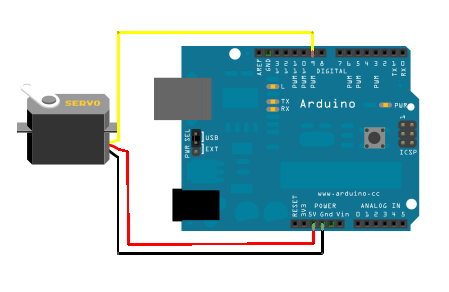
The servo has three contacts, which are colored in different colours. The brown wire leads to ground, the red wire leads to +5V power, the orange or yellow color- signal. The device is connected to Arduino through the breadboard as shown in the figure. The orange wire (signal) is connected to the digital pin, black and red - to ground and power, respectively. To control a servo motor, it is not required to connect specifically to the shim pins - we have already described the principle of servo control earlier.
It is not recommended to connect powerful servos directly to the board. they create a current that is not compatible with life for the Arduino power circuit - you'll be lucky if the protection works. The most common symptoms of servo overload and misfeeding are servo twitching, unpleasant sound and reboot the board. For power, it is better to use external sources, be sure to combine the grounds of the two circuits.
Arduino servo control sketch
Controlling a servo directly by changing the pulse duration in the sketch is not a trivial task, but fortunately we have an excellent Servo library built into the Arduino development environment. We will consider all the nuances of programming and working with servos in a separate article. Here we present the simplest example use Servo.
The algorithm of work is simple:
- First we include Servo.h
- Create an object of the Servo class
- In the setup block, specify which pin the servo is connected to
- We use the methods of the object in the usual C++ way. The most popular is the write method, to which we feed an integer value in degrees (for a 360 servo, these values will be interpreted differently).
An example of a simple sketch for working with a servo
An example of a project in which we immediately first set the servomotor to zero angle, and then rotate it 90 degrees.
#include
Sketch for two servos
And in this example, we are working with two servos at once:
#include
Servo control with potentiometer
In this example, we turn the servo depending on the value received from the potentiometer. We read the value and convert it to an angle using the map function:
//Fragment standard example using the Servo library void loop() ( val = analogRead(A0); // Read the value from the pin to which the potentiometer is connected val = map(val, 0, 1023, 0, 180); // Convert a number in the range from 0 to 1023 to a new range - 0 to 180. servo.write(val); delay(15); )

Characteristics and connection of SG-90
If you are looking to buy the cheapest and simplest servo, then the SG 90 is the best choice. This servo is most often used to control small, lightweight machines with a rotation angle of 0° to 180°.
Specifications SG90:
- Command processing speed 0.12s/60 degrees;
- Power supply 4.8V;
- Operating temperatures from -30C to 60C;
- Dimensions 3.2 x 1.2 x 3 cm;
- Weight 9 g.
Description of SG90
Wire colors are standard. The servo is inexpensive and does not provide precise settings for start and end positions. In order to avoid unnecessary overloads and characteristic crackling in the position of 0 and 180 degrees, it is better to set extreme points at 10° and 170°. When operating the device, it is important to monitor the supply voltage. If this indicator is too high, it may damage mechanical elements gear mechanisms.
MG995 and MG996 tower pro servos
The MG995 servo is the second most popular servo model most often connected to Arduino projects. These are relatively inexpensive servomotors with much the best performance compared to SG90.
Specifications MG995
The output shaft on the MG995 rotates 120 degrees (60 in each direction), although many sellers indicate 180 degrees. The device is made in a plastic case.
- Weight 55 g;
- Torque 8.5 kg x cm;
- Speed 0.2s/60 degrees (at 4.8V);
- Working power 4.8 - 7.2V;
- Operating temperatures - from 0C to -55C.
Description of MG995
The connection to the arduino also occurs via three wires. In principle, for amateur projects, it is allowed to connect the MG995 directly to the Arduino, but the motor current will always create a dangerous load for the inputs of the board, so it is recommended to still power the servos separately, remembering to connect the ground of both power circuits. Another option that makes life easier is to use ready-made servo controllers and shields, which we will review in a separate article.
The MG996R is similar to the MG995 in terms of features, only it comes in a metal case.
Converting a servo to a continuous rotation servo
As described above, the servo is controlled by variable width pulses that set the angle of rotation. The current position is read from the potentiometer. If the shaft and potentiometer are disconnected, the servomotor will assume the position of the potentiometer slider as at the midpoint. All these actions will lead to the fact that the feedback will be removed. This allows you to control the speed and direction of rotation on the signal wire, and create a continuous rotation servo. It is important to note that a constant rotation servo cannot rotate through a certain angle and make a strictly specified number of revolutions.
To perform the above steps, you will have to disassemble the device and make changes to the design.
In the Arduino IDE, you need to create a small sketch that will put the rocker in the middle position.
#include
After that, the device must be connected to the Arduino. When connected, the servo will start to rotate. It is necessary to achieve its complete stop by adjusting the resistor. After the rotation stops, you need to find the shaft, pull the flexible element out of it and install it back.
This method has several drawbacks - setting the resistor to a complete stop is unstable, with the slightest shock / heating / cooling, the adjusted zero point can go astray. Therefore, it is better to use the method of replacing the potentiometer with a trimmer. To do this, pull out the potentiometer and replace it with a trimmer with the same resistance. The zero point must be adjusted with a calibration sketch.
Any method of converting a servo to a continuous rotation servo has its drawbacks. First, it's hard to set up zero point, any movement can bring it down. Secondly, the control range is small - with a small change in the pulse width, the speed can change significantly. You can expand the range programmatically in Arduino.
Conclusion
Servo drives play a very important role in many Arduino projects, from robotics to systems. smart home. Everything that is connected with movement traditionally requires special knowledge and creating a full-fledged correctly working drive is not an easy task. But with servo motors, you can simplify the task in many cases, so the servo is constantly used even in entry-level projects.
In this article, we have tried to reveal different aspects using servos in arduino projects: from connecting to writing sketches. By choosing the most simple model servos (e.g. sg 90) you can easily repeat the examples given and create your first projects in which something moves and changes. We hope this article will help you with this.
This article discusses servos: their device, purpose, tips for connecting and controlling, types of servos and their comparison. Let's get started and start with what a servo is.
The concept of a servo
A servo drive is most often understood as a mechanism with an electric motor, which can be asked to turn to a given angle and hold this position. However, this is not a complete definition.
To put it more fully, a servo drive is a drive controlled through a negative feedback, which allows precise control of motion parameters. A servo drive is any type of mechanical drive that includes a sensor (position, speed, force, etc.) and a drive control unit that automatically maintains the necessary parameters on the sensor and the device according to a given external value.
In other words:
The servo drive receives the value of the control parameter as input. For example, the angle of rotation.
The control unit compares this value with the value on its sensor.
Based on the result of the comparison, the drive performs some action, such as turning, accelerating or decelerating, so that the value from the internal sensor becomes as close as possible to the value of the external control variable.
The most common are servos that hold a given angle, and servos that maintain a given speed of rotation.
A typical hobby servo is shown below.
How are servos arranged?
Servo device
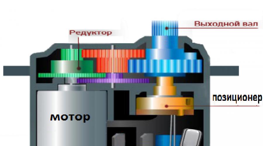
Servo drives have several components.

Drive - electric motor with gearbox. To convert electricity into mechanical rotation, you need electric motor. However, often the motor speed is too high for practical use. Used to slow down the speed reducer: a mechanism of gears that transmits and converts torque.
By turning the electric motor on and off, we can rotate the output shaft - the final gear of the servo, to which we can attach something that we want to control. However, in order for the position to be controlled by the device, feedback sensor - encoder, which will convert the steering angle back into an electrical signal. A potentiometer is often used for this. When the potentiometer slider is turned, its resistance changes, proportional to the angle of rotation. Thus, it can be used to set current position mechanism.
In addition to the electric motor, gearbox and potentiometer, the servo drive has an electronic filling that is responsible for receiving an external parameter, reading values from the potentiometer, comparing them, and turning the motor on / off. She is responsible for maintaining negative feedback.
There are three wires going to the servo. Two of them are responsible for powering the motor, the third delivers a control signal that is used to set the position of the device.
Now let's see how to control the servo externally.
Servo control. Control signal interface
To indicate the desired position to the servo, a control signal must be sent along the wire intended for this. Control signal - pulses of constant frequency and variable width.

The position that the servo should take depends on the length of the pulses. When a signal enters the control circuit, the pulse generator in it produces its own pulse, the duration of which is determined through a potentiometer. Another part of the circuit compares the duration of the two pulses. If the duration is different, the electric motor is turned on. The direction of rotation is determined by which of the pulses is shorter. If the pulse lengths are equal, the electric motor stops.
Most often in hobby servos, pulses are produced at a frequency of 50 Hz. This means that a pulse is emitted and received once every 20 ms. Typically, a pulse duration of 1520 µs means that the servo should take the middle position. Increasing or decreasing the pulse length will cause the servo to turn clockwise or counterclockwise respectively. In this case, there are upper and lower limits of the pulse duration. In the Servo library for Arduino, the default pulse lengths are 544 µs for 0° and 2400 µs for 180°.
Please note that on your particular device, the factory settings may be different from the standard ones. Some servos use a pulse width of 760 µs. In this case, the middle position corresponds to 760 µs, in the same way as in conventional servo drives the average position corresponds to 1520 µs.
It is also worth noting that these are just generally accepted lengths. Even within the same servo model, there may be a manufacturing error that causes the operating range of pulse lengths to be slightly different. For precise work each specific servo must be calibrated: through experiments, it is necessary to select the correct range that is specific to it.
What else is worth paying attention to is the confusion in terminology. Often the way to control servos is called PWM / PWM (Pulse Width Modulation) or PPM (Pulse Position Modulation). This is not the case, and using these methods may even damage the drive. The correct term is PDM (Pulse Duration Modulation). In it, the length of the pulses is extremely important and the frequency of their appearance is not so important. 50Hz is the norm, but the servo will work correctly at both 40 and 60Hz. The only thing to keep in mind is that with a strong decrease in frequency, it can work in jerks and at reduced power, and with a strong increase in frequency (for example, 100 Hz), it can overheat and fail.
Servo Specifications
Now let's figure out what servos are and what characteristics they have.
Torque and turning speed
First, let's talk about two very important characteristics servo: about torque and about turning speed.
The moment of force, or torque, is a vector physical quantity equal to the product of the radius vector drawn from the axis of rotation to the point of application of the force by the vector of this force. Characterizes the rotational action of force on a rigid body.

Simply put, this characteristic shows how heavy a load the servo is able to keep at rest on a lever of a given length. If the torque of the servo is 5 kg × cm, then this means that the servo will hold a 1 cm long lever on the weight in a horizontal position, on the free end of which 5 kg are hung. Or, equivalently, a lever 5 cm long, from which 1 kg is hung.
Servo speed is measured by the amount of time it takes the servo arm to rotate 60°. A characteristic of 0.1s/60° means that the servo turns 60° in 0.1s. From it it is easy to calculate the speed in a more familiar value, revolutions per minute, but it so happened that when describing servos, such a unit is most often used.
It is worth noting that sometimes you have to find a compromise between these two characteristics, because if we want a reliable, enduring big weight servo, then we must be prepared that this mighty installation will slowly turn. And if we want a very fast drive, then it will be relatively easy to unbalance it. When using the same motor, the balance is determined by the configuration of the gears in the gearbox.
Of course, we can always take a plant that consumes more power, as long as its characteristics meet our needs.
Form factor
Servos vary in size. And although there is no official classification, manufacturers have long adhered to several sizes with a generally accepted location. fasteners. They can be divided into:
small
standard
They have the following characteristic dimensions:
There are also so-called servo drives " special kind» with dimensions that do not fall into this classification, but the percentage of such servos is very small.
Internal interface
Servo drives are either analog or digital. So what are their differences, advantages and disadvantages?
Outwardly, they are no different: electric motors, gearboxes, potentiometers are the same, they differ only in internal control electronics. Instead of a special analog servo chip, the digital counterpart can be seen on the board with a microprocessor that receives pulses, analyzes them and controls the motor. Thus, in the physical version, the difference is only in the way the pulses are processed and the motor is controlled.

Both types of servo take the same control pulses. The analog servo then decides whether to change the position and sends a signal to the motor if necessary. This usually happens at a frequency of 50 Hz. Thus, we get 20 ms - the minimum reaction time. At this time, any external influence can change the position of the servo. But this is not the only problem. At rest, no voltage is applied to the electric motor, in the event of a slight deviation from equilibrium, a short signal is given to the electric motor low power. The larger the deviation, the stronger the signal. Thus, with small deviations, the servo will not be able to quickly rotate the motor or develop a large torque. "Dead zones" are formed in time and distance.
These problems can be solved by increasing the reception frequency, signal processing and motor control. Digital servos use a special processor that receives control pulses, processes them and sends signals to the motor at a frequency of 200 Hz or more. It turns out that the digital servo is able to respond faster to external influences, develop the necessary speed and torque faster, which means it is better to maintain a given position, which is good. Of course, at the same time it consumes more electricity. Also, digital servos are more difficult to manufacture, and therefore are noticeably more expensive. Actually, these two disadvantages are all the disadvantages that digital servos have. In technical terms, they unconditionally defeat analog servos.
Gear materials
Gears for servos come in a variety of materials: plastic, carbon, metal. All of them are widely used, the choice depends on the specific task and on what characteristics are required in the installation.

Plastic, most often nylon, gears are very light, not subject to wear, and are most common in servo drives. They do not withstand heavy loads, but if the loads are expected to be small, then nylon gears are the best choice.
Carbon gears are more durable, practically do not wear out, and are several times stronger than nylon ones. The main disadvantage is the high cost.
Metal gears are the heaviest, but they can withstand maximum loads. They wear out pretty quickly, so you have to change the gears almost every season. Titanium gears are favorites among metal gears, and both technical specifications, as well as for the price. Unfortunately, they will cost you quite a lot.
Brushed and brushless motors
There are three types of servo motors: conventional core motor, coreless motor and brushless motor.

A conventional core motor (right) has a dense iron rotor with wire windings and magnets around it. The rotor has multiple sections, so as the motor spins, the rotor causes the motor to vibrate slightly as the sections pass the magnets, resulting in a servo that vibrates and is less accurate than a coreless motor servo. The hollow rotor motor (left) has a single magnetic core with a cylinder or bell shaped winding around the magnet. The coreless design is lighter in weight and has no sections, resulting in faster response and smooth, vibration-free operation. Such motors are more expensive, but they provide more high level control, torque and speed compared to standard.

Servo drives with a brushless motor have appeared relatively recently. The advantages are the same as for other brushless motors: there are no brushes, which means they do not create resistance to rotation and do not wear out, the speed and torque are higher with a current consumption equal to the collector motors. Brushless motor servos are the most expensive servos, but they offer better performance than servos with other types of motors.
Connecting to Arduino
Many servos can be connected directly to the Arduino. To do this, they come from a cable of three wires:
red - food; connects to the 5V pin or directly to the power supply
brown or black - earth
yellow or white - signal; connects to the Arduino digital output.
To connect to the Arduino, it will be convenient to use a port expander board, such as Troyka Shield. Although with a few extra wires it is possible to connect the servo via the breadboard or directly to the Arduino pins.
It is possible to generate control pulses yourself, but this is such a common task that the Servo standard library exists to simplify it.
Food restriction
A typical hobby servo draws over 100 mA during operation. At the same time, Arduino is capable of delivering up to 500 mA. Therefore, if you need to use a powerful servo in a project, it makes sense to think about isolating it into a circuit with additional power.
Consider the example of connecting a 12V servo: 
Limitation on the number of connected servos
On most Arduino boards, the Servo library supports control of no more than 12 servos, on the Arduino Mega this number grows to 48. At the same time, there is a small side effect using this library: if you are not working with an Arduino Mega, it becomes impossible to use the analogWrite() function on pins 9 and 10, regardless of whether servos are connected to these pins or not. Up to 12 servos can be connected to the Arduino Mega without disrupting the PWM / PWM function, when using more servos, we won't be able to use analogWrite() on pins 11 and 12.
Servo library functionality
The Servo library allows program control servos. To do this, a variable of type Servo is created. Management is carried out by the following functions:
attach() - Attaches a variable to a specific pin. There are two possible syntaxes for this function: servo.attach(pin) and servo.attach(pin, min, max) . In this case, pin is the number of the pin to which the servo is connected, min and max are the pulse lengths in microseconds, which are responsible for the rotation angles of 0° and 180°. By default, they are set to 544 µs and 2400 µs, respectively.
write() - instructs the servo to accept some parameter value. The syntax is: servo.write(angle) where angle is the angle the servo should turn.
writeMicroseconds() - gives a command to send a pulse of a certain length to the servo, is a low-level analogue of the previous command. The syntax is: servo.writeMicroseconds(uS) where uS is the length of the pulse in microseconds.
read() - reads present value corner where the servo is located. The syntax is: servo.read() returns an integer value between 0 and 180.
attached() - Checks if a variable has been attached to a specific pin. The syntax is: servo.attached() returns boolean true if the variable has been attached to any pin, or false otherwise.
detach() - performs an action, reverse action attach() , that is, detaches the variable from the pin to which it was assigned. The syntax is: servo.detach() .
All Servo2 library methods are the same as Servo methods.
An example of using the Servo library
Instead of a conclusion
Servo drives are different, some are better - others are cheaper, some are more reliable - others are more accurate. And before you buy a servo, you should keep in mind that it may not have the best characteristics, as long as it is suitable for your project. Good luck in your endeavors!
Servo drives usually have a limited rotation angle of 180 degrees. AT this case consider a "modified" servo with an unlimited angle of rotation of the axis. 
TTX from the seller's page
Size:40*20*37.5+5mm drive shaft
weight:38g
wire length: 320 mm
Speed: 0.19sec/60 degree (4.8V)
0.22sec/60 degree (6V)
the speeds are most likely mixed up, at 6 volts the servo should be faster
torque: 5kg. cm. at (4.8 V)
5.5kg.cm.at (6V)
voltage:4.8V-6V
Delivery set standard 
4 rocking chairs of different shapes
4 bushings, 4 rubber dampers and 4 screws for mounting the servo
and another small screw for attaching the rocking chair to the shaft ran away from the photo :)
Appearance inspires confidence, nothing to the touch, small shoals of casting only in the area of \u200b\u200bthe mounting ears, a sticker is slightly crooked (yes, a tautology!). The wire is soft, the connector sits well on the pins. 
Well, now the opening:
Who did not know how it works: in the case there is a motor, a control board and a variable resistor, by the position of which the servo determines the angle of the axis.
The gearbox in this servo is plastic, the resource is less than that of a metal one and does not like large loads. Sleeve under central axis copper or some of its alloys. The output shaft has a bearing. Lubricants can be added 
Electrical part 

Brains that control the direction and speed of rotation, a variable rezjuk and an electric motor.
And now, attention, "life hack", how to make a regular servo into a constant rotation servo 
In the original, the variable is stuck with its axis into the output shaft from inside the servo, in the modified shaft, apparently, it was bitten off / broken off at the assembly stage, the resistor is set to the central position so that the shaft does not rotate at rest. If you go further, you can throw it out completely and replace it with 2 identical constant resistors, it’s convenient to put something smd-shnoe on the control board.
Total:
serva as serva, not space, but not consumer goods,
can be found cheaper and with a metal gearbox
PS
As correctly noted in the comments, I completely forgot to mention how the servo is controlled, the servo is powered by 5-6 volts and a ppm signal through the third wire.
The most common control options:
1) we connect the power on one side, on the other hand, the output for 3 “consumers” (servers, motors, etc.) power and PPM signal, you can adjust the speed and direction of rotation of the servo with the knob
2) RC equipment at the receiver outputs the same ppm signal.
3) drive an arduino
Video
pps
As a result of the “modification”, the servo has lost feedback, the brains do not know the real position of the shaft and the direction of rotation, consider this moment if you are going to buy it.
To disassemble our servo we need a screwdriver. Because I disassemble a very small servo, then I need an appropriate screwdriver. Personally, I use screwdrivers from some cheap Chinese kit. I bought it at a kiosk in underpass at a price of about $ 5, so it's not very expensive.
To open the servo, you need to unscrew only four screws. They are located on the bottom cover. Unscrew:

After removing the cover, you can see the control unit. I won't go into details, I'm going to remove it from here anyway. You can also see the motor to which two wires lead.

There is also a cover on top, removing which you can see the gears of the gearbox. It is worth noting that two of them are fixed on the potentiometer - this is quite important, since in order for the gearbox to continue to perform its function, we will have to actually break the potentiometer - we will use it simply as an axis for the gears.

Actually, it is necessary to remove all the gears from the servo drive and put them aside for a while. We take out the potentiometer (by the way, it is also a variable resistor) from the case by gently pushing it from the bottom side of the servo with a screwdriver.

This is the moment of the point of no return. Of course, it will always be possible to solder everything back, but this is already more difficult. So - bite off the potentiometer.

Then, using the same method, we separate the control board with power and signal wires.

Then we bite off the wires from the motor. Here, be careful and do not bite off the contacts from the motor itself - if you are not sure, it is better to leave the wire with a margin. Then it can be soldered. I bite off the wire to the very contact.


Let's take an inventory.

Everything seems to be in place. Now we take our potentiometer in hand.

The fact is that now it also rotates only at a certain angle. And since it is an axis and the largest gear is attached to it, on which we will actually mount the wheel later on, we must make sure that it rotates constantly. We take out two metal plates which prevent it. We get:

I hope the photos make it clear what I did. I ripped it out with small pliers, since there was nothing more suitable at hand.
Now you need to cut the limiter on the gear itself. It looks like a ledge from the bottom of the gear. It is easy to find it, it looks like this.

Rezhem.

And actually after that you can start assembling the gearbox back into the housing. We insert back the axis we made earlier from the potentiometer.

Next, one by one gears starting with the smallest. Be careful when inserting the last gear - it is specially attached to the axis of the former potentiometer, since the tip of the axis is made in the shape of a letter D. It is necessary that this protrusion gets into the recess in the gear. It turns out something similar to the following picture.

We put the top cover on the gearbox so that it does not fall apart in the course of further work.

Well, there aren't many left. We take a wire with a connector that we previously bit off from the board and separate the wiring in it. Do not separate from long distance In fact, one centimeter is enough.

We clean two of them (in fact, any, but I used red and green). It is enough to cut off about 3mm of insulation. For our purposes - more than.

We simply bend the remaining unstripped wire so that it does not interfere with us.

Let's move on to hot. It's time to heat up the soldering iron. During the time that the soldering iron is heated, I made the servo drive more comfortable in the grip.


First of all, we will need to remove the remnants of the old solder that remained on the engine contacts. I do this with a desoldering pump, preheating the contact with a soldering iron to such a state that the solder melts. The main thing here is not to overdo it - the back cover of the motor is still plastic and does not like to warm up for a long time. The process looks something like this:


I understand that it is possible and not very noticeable what I did, but there was practically no solder left on the contacts, which is what I was trying to achieve.

There are wonderful articles on soldering in DI HALT "a. He is generally a genius, it seems to me. Link to his blog, there is a lot of things besides soldering, in fact, just search.
In short, in order to make good soldering, you must always get rid of the old solder at the beginning.
It remains to solder two wires. Who is familiar with soldering - cope in 5 seconds. Who, like me, for the second time in my life, normally took up a soldering iron, it will take a little more time, but still - it's very simple, everyone can do this.
During soldering, I use a flux, which, admittedly, makes the job easier at times and the quality of soldering with it is much easier to ensure. Personally, on the advice of me, again, DI HALT "and on his blog I already managed to fall in love with the LTI-120. I have it in such a fashionable jar right away with a brush.

We tighten four screws.

That's all, the alteration of the servo is over. Having re-fixed the servo more comfortably and more firmly in the grip, you can start testing.

This time I will not be sophisticated with the controller, but simply apply voltage from the power supply to 5V to the green and red wires. Attention, the video shows a rather loud sound from the operation of the drive.
As you can see, now nothing prevents our servo from rotating without stopping. The sound emitted by the drive is not really quiet, but in principle it is tolerable. That's probably all for today.
The simplest of the robots are 2-wheeled or 4-wheeled. Such a robot can be based on a chassis from a radio-controlled car, but not everyone may have it at hand or it may be a pity to screw it up. You can also make the chassis yourself, but putting the wheels directly on the motor is not very good decision, the motor needs to be recharged to slow down, for this you need a gearbox. Getting a ready-made chassis or a gearbox or a motor with a gearbox turned out to be not such an easy task, unlike servos. Almost any servo drive can be easily converted into a motor with a gearbox.
Wheels can be glued directly to the rocking chair of such a motor, and the servo body is convenient for mounting.
ATTENTION! The device of other servos may differ, and, therefore, this manual look only partly.
The simplest and cheapest servo was taken as a basis:

First, let's disassemble it.

First, we remove unnecessary electronics, bite off the driver, we will control the motor directly. Next, let's start modifying the mechanics, remove the first gear with an external shaft and remove the stroke limiter from it.


We take out the resistor and bite out the limiter located on its body.

We collect all the mechanics back and check if everything moves successfully.
The next step is to solder the wire to the motor.

We assemble the former servo into a new motor with a gearbox.
Everything is ready, if you have not made any mistakes, you can enjoy the work.