Continuous blowing separator. Continuous and periodic boiler blowdown Pressure in the continuous blowdown separator
Continuous blow separatorcyclone type is designed to separate the boiler blowdown water into steam and water formed from the blowdown water of steam boilers when its pressure is reduced from intra-boiler pressure to the pressure in the separator and for the purpose of subsequent use of the heat of water and steam. Separation occurs due to the action of centrifugal forces caused by the tangential input of water into the separator. After this, steam with a high degree of dryness is supplied to the consumer.
| Continuous blowing separator SNP-0.15-1.4 |
Continuous blowing separators SNP can be used in condensate collection systems in order to reduce the consumption of steam consumed and heat losses from the discharged steam-condensate mixture.
In addition to the tangential supply of condensate (blowdown water), the blowdown separators are equipped with vertical louvered drop eliminators for drying the secondary boiling steam.
Main parameters and technical characteristics
| Name | Unit change |
SNP-0.15-0.06 (Du-300) |
SNP-0.15-0.8 (Du-300) |
SNP-0.15-1.4 (Du-300) |
SP-0.28-0.45 (Du-450) |
SP-0.7-0.6 (Du-600) |
SP-1.4-0.8 (Du-800) |
SP-1.5-0.8 (Du-800) |
SP-5.5-1.4 (Du-800) |
| Working pressure | MPa | 0,06 | 0,8 | 1,4 | 0,45 | 0,6 | 0,8 | 0,8 | 1,4 |
| Temperature | o C | 113 | 174,5 | 194 | 170 | 170 | 170 | 175 | 127 |
| Test pressure | MPa | 0,16 | 1,0 | 1,75 | 1,0 | 1,0 | 1,0 | 1,1 | 0,2 |
| Steam capacity | t/h | 1 | 1 | 1 | 0,7 | 2,75 | 5,26 | 12,5 | 70,0 |
| Capacity | m 3 | 0,15 | 0,15 | 0,15 | 0,28 | 0,7 | 1,4 | 1,5 | 5,5 |
| Dry weight without components | kg | 175 | 175 | 245 | 470 | 756 | 1114 | 1200 | 1878 |
| Weight of components | kg | 85 | 85 | 90 | 110 | 120 | 128 | 128 | 150 |
Design and principle of operation
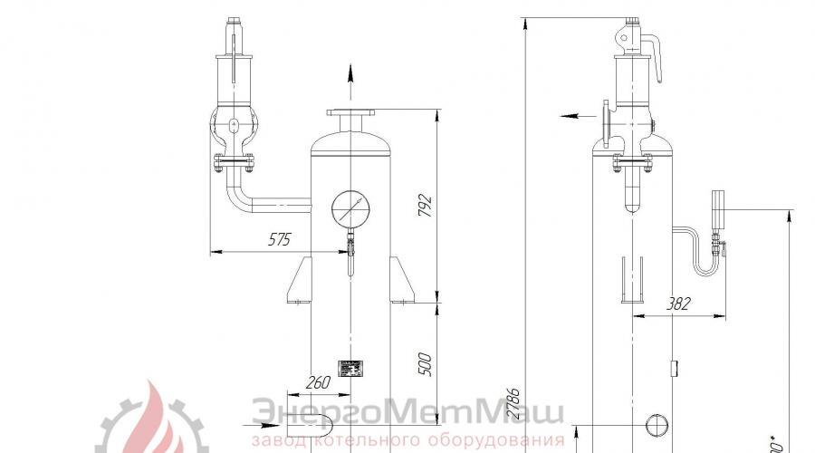
The continuous blowing separator is a vertical cylindrical vessel (see Fig. 1) with elliptical bottoms, oppositely placed inlet pipes, steam and water outlet pipes, a level indicator for visual control, a spring safety valve, and a float steam trap that automatically maintains the water level. The swirling of the flow is carried out due to the organized supply of the steam-water mixture to the inner wall of the separator with the installation of internal guide devices. Typically, the blowdown water consumption for the separator ranges from 1% to 5% of the boiler output.
Separation into steam and water occurs in the middle part of the separator. The steam, while maintaining rotational motion, is directed into the steam space and discharged through a pipe located on the upper bottom. Water flows down the inner surface of the separator into the water volume and is discharged through a pipe located in the lower part of the housing. A fitting is provided on the lower bottom for draining water from the separator when it is turned off and for periodically cleaning the lower part of the water volume from sludge and contaminants.
 |
| Rice. 1. Drawing of a continuous blowing separator |
 |
| Rice. 2. Piping diagram of the continuous blowing separator |
On the cylindrical part of the body of the continuous blowdown separator, two supports are welded for installing the separator and nozzles for the tangential supply of the steam-water mixture of boiler blowdown water to the separator. In the upper bottom of the separator there is a pipe with a flange for the outlet of separated steam, and in the lower bottom there is a fitting with a valve for draining water from the separator when it is turned off and for the possibility of periodically removing sludge and contaminants from the lower part of the water volume.
The lower cylindrical part of the housing has a float-type condensate drain and a level indicator. Using the level indicator, the water level is visually monitored. The float-type condensate trap is designed to automatically maintain a constant water level in the separator.
The steam is directed into the steam space, and the separated water flows down the inner wall of the separator into the water volume.
Installation procedure
Installation of the purge separator is carried out in accordance with the technical documentation developed by specialized design organizations and the requirements of the installation instructions.
To prevent a possible increase in pressure, a spring safety valve is provided on the separator body.
The continuous blowing separator is installed in a vertical position on pre-assembled support beams. Next, instrumentation, safety devices, a float condensate trap are installed and piping is performed.
The installation of the SNP purge separator must provide the possibility of inspecting, repairing and cleaning it from both the internal and external sides, and must eliminate the danger of it tipping over. Hanging of the separator on the connecting pipelines is not allowed.
During installation, for ease of maintenance of the separator, platforms and stairs can be installed, which should not interfere with the strength, stability and possibility of free inspection and cleaning of the outer surface.
After installing and securing the continuous blowing separator, piping and equipping it with fittings, it is necessary to perform a hydraulic (pneumatic) test. After the hydraulic test, the separator and pipelines are washed, the functionality of the fittings, float steam trap, and safety valve is checked, after which the separator is put into operation.
Maintenance and Operation
The condition for normal and reliable operation of a continuous blowdown separator is to ensure continuous removal of steam and water from the separator and maintain the pressure in the separator within the established limits. This is achieved if the float steam trap and safety valve are in good condition.
The continuous blowdown separator must be under constant supervision by operating personnel. The proper condition of the float steam trap should be properly monitored:
- check the sight glass, which must be installed behind the condensate drain, once per shift;
- Monitor steam pressure at least 3 times per shift;
- at least 3 times per shift, monitor the presence of a normal level of condensate in the housing using the water indicator glass;
- Purge the level indicator at least once per shift, depending on the quality of the purge water.
The safety valve must be forcibly undermined at least once per shift, followed by monitoring of the return of the valve to its original position and the absence of steam leaks. Periodic inspection of the separator should be carried out both for preventive purposes and to identify the causes of problems that have arisen.
Inspection and cleaning of the blowdown separator housing should be carried out at least once every 2-3 years when the separator is shut down for routine and major repairs.
Continuous blowing separators must undergo technical inspection after installation, before putting into operation, periodically during operation and, if necessary, extraordinary inspection.
In case of long-term repairs, as well as insufficient density of the shut-off valves, the equipment being repaired should be switched off. The thickness of the plugs must correspond to the parameters of the working environment.
When loosening bolts on flange connections, care must be taken to ensure that steam and water inside the purge separator and piping do not cause burns to people.
Polar Division of OJSC MMC Norilsk Nickel
PA "Norilskenergo"
I N S T R U C T I O N
for maintenance of separators for continuous blowing of boilers TGME - 464.
PI –188-50-05-03
Norilsk - 2003
Polar Division of OJSC MMC Norilsk Nickel
PA "Norilskenergo"
I CONFIRM:
Chief engineer of CHPP-3
V.M.Lomenko
"___"_____________2003
I N S T R U C T I O N
for maintenance of separators for continuous blowing of boilers TGME-464.
PI –188-50-05-03
1. A common part.
This instruction has been compiled on the basis of the factory instructions for servicing continuous blowing separators (1RNP, 2RNP) and is mandatory for execution by NSS, NS KTC, Art. boiler equipment operator, line operator.
2. Purpose of continuous blowing separators (expanders).
Continuous blowing separators are designed to separate the steam-water mixture coming from boilers during its continuous blowing, removing from the boiler non-stick sludge suspended in the boiler water.
3. Device and technical characteristics.
There are two continuous blowing separators of different types installed in the boiler room.
1RNP is supplied with water for continuous blowdown of boilers No. 1, 2.
Water for continuous blowdown of boilers No. 3 and 2 is supplied to 2RNP.
3.1. Continuous blowing separator (1RNP) type TK - 3 single-casing, vertical type. Consists of a cylindrical body, two elliptical bottoms, supports, fittings:
Supply of steam-water mixture;
Steam exhaust;
Water drainage;
Safety valve connections;
VUK affiliations;
Level regulator.
Float type level regulator. There is a hole on the body with a diameter of DN 450 mm. The supply of steam-water mixture from boilers No. 1, 2 is made from two opposite sides tangentially to the circumference of the shell into the annular valve. Separation of the steam-water mixture is carried out due to the action of centrifugal forces.
The separator is equipped with one safety valve type SPPK - 4 - 16 - 150. The valve is adjusted to an operating pressure of 1.15 pp.
Separator characteristics:
Case diameter – 1500 mm;
Volume – 5.5 m3;
Temperature – 170 °C;
Medium – saturated steam water;
Steel grade – VST 3 PS 5.
3.2. Continuous blowing separator (2RNP) TKZ type SP – 1.5 u, centrifugal. Determination of steam from the incoming flow of steam-water mixture occurs on special blades with a small radius of curvature. The device is single-case, vertical type. Consists of a cylindrical body, two elliptical bottoms, supports, fittings:
Supply of steam-water mixture;
Steam exhaust;
Water drainage;
Safety valve connections;
Level indicator connections.
Inside the apparatus there are: a blade device, a grate, a cone that prevents the steam-water mixture from affecting the water level, and an anti-twist device in the lower bottom. The separator is equipped with two safety valves of the SPPK – 4 – 16 – 150 type, one on the body, the other on the steam exhaust pipeline. Level regulator - float type.
Separator characteristics:
Case diameter – 800 mm;
Working pressure – 8 kgf/cm2;
Volume – 1.5 m3;
Temperature – 170 °C;
Medium – saturated steam water;
Pressure at G.I. – 11 kgf/cm2;
Water productivity – 28.4 t/h;
Steam output – 12.5 t/h.
4. Connection diagram 1 RNP.
Boiler water from two external cyclones of the boiler through a pipeline DN 28x3 enters the continuous blowdown separator or into the periodic blowdown expander when the RNP is not operating. The following are installed in series on the pipeline: two shut-off valves DN - 20, a flow washer, a pressure regulator DN - 20, a shut-off valve DN - 20 on the line to the separator, a shut-off valve DN - 20 on the line to the periodic blowdown expander. After the separator, the steam is discharged into the general station collector 6 atm.
The following are installed on the steam pipeline:
check valve, gate valve DN - 150. Before the check valve there is an air vent line to the funnel; before the gate valve there is an inspection line into the exhaust pipeline of the safety valve. Water after the separator enters the periodic blowdown expander and then into the bubbler.
The water level in the separator is maintained by a level regulator and controlled by the VUK. When the level regulator is turned on, the valves DNP - 2, 3 and the valves of the float chamber for water and steam must be open. Valve DNP – 1 must be closed.
5. The procedure for including 1RNP in work.
Before putting the separator into operation, it is necessary to check the condition:
Thermal insulation;
Fittings and fasteners for flange connections;
Control and measuring instruments;
Water indicator and its lighting;
Platforms and stairs.
Gate valve to the DNP level regulator – 2;
Gate valve after the DNP level regulator – 3;
A valve in addition to the DNP level regulator – 1;
Float chamber valve for steam and water;
Air vent valve;
Valve for pressure gauge;
The valve on the steam line to the manifold is 6 ati (1PNP).
The separator must be turned on while warming up in the following sequence:
Slowly open valve DN – 20 to pressure regulator NP – 1, 2;
Blow up the valve DN - 20 (NP - 3) and the pressure regulator, feed the steam-water mixture into the separator without allowing hydraulic shocks.
Warm up the separator for 20 - 30 minutes, controlling the pressure and steam output from the vent;
At a pressure of 1 ati, blow out the water and steam valves of the VUK and turn on the VUK in operation;
Close the valve DNP – 1 in addition to the level regulator;
Gradually fully open valve NP – 3;
When the level increases, check the operation of the regulator;
Separators and expanders of continuous and periodic blowdown are designed to separate into steam and water the steam-water mixture formed from the blowdown water of steam boilers, condensate from steam receivers, drainage of steam pipelines when its pressure is reduced to the pressure in the separator (expander), with subsequent use of the heat of water and steam.
Separators and expanders can be used in condensate collection systems to reduce the consumption of steam and heat losses from the discharged steam-condensate mixture.
The expanders have the simplest separating device - a tangential supply of condensate (blow-down water).
In addition to the tangential supply of condensate (blowdown water), the separators are equipped with vertical louvered drop eliminators for drying the secondary boiling steam.
DU 300-800 (Sarenergomash)
Modifications
This section presents serial separators and expanders:
Separators and expanders are manufactured in accordance with TU 3113-017-00210714-2008.
OKP code 31 1336.
The plant has the ability to develop and manufacture separators (expanders) according to technical specifications.
Design and principle of operation of a continuous blowing separator
The separator is a vertical cylindrical vessel of a welded structure and consists of a body with a lower elliptical bottom welded to it; The upper elliptical bottom is connected to the body using a flange connector.
In the middle part of the body, 2 or 4 supports are welded for installing the separator in a suspended state on support beams.
In the lower part of the housing there is a receiving device, consisting of two concentrically installed shells and two tangentially welded pipes into the housing, designed to receive tangentially supplied purge water.
In the upper part of the housing, a separating device is bolted to the ring, consisting of a set of specially bent blades and designed to separate small drops of water from steam.
A constant level of separated water is automatically maintained by a float level regulator built into the DN 150 fitting in the lower part of the housing.
To visually monitor the level of separated water, the separator is equipped with a water-indicating device, consisting of a water-indicating glass and valve-type taps.
To monitor the operating pressure in the steam space of the separator (for separators SP-0.28-0.45; SP-0.7-0.6; SP-1.4-0.8; SP-1.5-0, 8); There is a pressure gauge indicating a measurement limit of up to 1.6 MPa (16 kgf/cm2) with a 3-way purge valve and a drain valve.
Cutting off steam pressure in the housing above the permissible level (7.5 kgf/cm2) is ensured by a full-lift flanged safety valve DN 50 Ru 16 kgf/cm2, equipped with a replaceable spring type I, operating at a pressure in the range of 7-13 kgf/cm2. Valve operation is adjusted to a pressure of 7.5 kgf/cm2. The upper part of the valve is closed by a cap, which contains an adjusting screw for setting the spring to the specified pressure. There is no safety valve in the SP-0.15-0.3 separator (working pressure 0.06 MPa).
The operation of the separator is to receive a steam-water mixture from the boiler, dividing it into steam and water due to the expansion and rotational movement of the flow in the separator receiving device. A precipitation operation takes place in the receiving device. The steam is finally dried in a separating device.
| Designation | Volume, m3 |
Pressure, MPa |
Temperature, °C |
Weight, kg |
| Separators | ||||
| SP-0.15-0.3 | 0,15 | 0,06 | 113 | 242,5 |
| SP-0.28-0.45 | 0,28 | 0,7 | 170 | 470 |
| SP-0.7-0.6 | 0,7 | 0,7 | 170 | 756 |
| SP-1.4-0.8 | 1,4 | 0,7 | 170 | 1113 |
| SP-1.5-0.8* | 1,5 | 0,78 | 175 | 1200 |
| SP-5.5-1.4** | 5,5 | 0,15 | 127 | 1878 |
| Extenders | ||||
| RP-0.12-0.35 | 0,12 | 0,35 | 148 | 400 |
| RP-0.18-0.45 | 0,18 | 0,9 | 180 | 140,2 |
| RP-0.4-0.44 | 0,4 | 0,56 | 162,5 | 555 |
| RP-0.5-0.7 | 0,5 | 0,1 | 121 | 620 |
| RP-0.6-0.6 | 0,6 | 0,2 | 133 | 385 |
| RP-1.4-0.7 | 1,4 | 0,6 | 165 | 1140 |
| RP-1.77-0.8 | 1,77 | 0,005 | 101 | 1200 |
| RP-2.6-1.0 | 2,6 | 0,01 | 102,3 | 1650 |
| RP-4.0-1.3 | 4 | 0,12 | 123 | 3410 |
| RP-4.84-1.2 | 4,84 | 1,48 | 201 | 2050 |
| RP-5.0-1.4 | 5 | 0,15 | 127 | 1650 |
| RP-7.5-2.0 | 7,5 | 0,15 | 127 | 3712 |
| RP-7.68-1.6 | 7,68 | 0,02 | 100,2 | 3615 |
| RP-8.1-1.8 | 8,1 | 0,15 | 127 | 2790 |
| RP-10.5-1.8 | 10,5 | 0,12 | 123,2 | 5113,7 |
| RP-22-2.6 | 22 | 0,001 | 100 | 11300 |
* - purge separator SP-1.5-0.8 is an analogue of separator SP-1.5U
** - purge separator SP-5.5-0.15 is an analogue of separator 5.5U
** - purge expander RP-7.5-2.0 is an analogue of the expander R-2000
Resource
The full designated service life is 20 years.
The warranty period is 24 months from the date of putting the unit into operation, but not more than 36 months from the date of shipment to the consumer.
DU 300 (BiKZ)
Continuous blowing separator, cyclone type, designed to separate the steam-water mixture when blowing steam boilers into steam and water due to the action of centrifugal forces caused by the tangential input of water into the separator.
Separators and expanders of continuous and periodic blowdown are designed to separate into steam and water the steam-water mixture formed from the blowdown water of steam boilers, condensate from steam receivers, drainage of steam pipelines when its pressure is reduced to the pressure in the separator (expander), with subsequent use of the heat of water and steam.
Separators and expanders can be used in condensate collection systems to reduce the consumption of steam and heat losses from the discharged steam-condensate mixture.
The expanders have the simplest separating device - a tangential supply of condensate (blow-out water).
In addition to the tangential supply of condensate (blowdown water), the separators are equipped with vertical louvered drop eliminators for drying the secondary boiling steam.
Modifications
This section presents serial separators and expanders:
Separators and expanders are manufactured in accordance with TU 3113-005-68215545-2014.
The plant has the ability to develop and manufacture separators (expanders) according to technical specifications.
Design and principle of operation of a continuous blowing separator
The separator is a vertical cylindrical vessel of a welded structure and consists of a body with a lower elliptical bottom welded to it; The upper elliptical bottom is connected to the body using a flange connector.
In the middle part of the body, 2 or 4 supports are welded for installing the separator in a suspended state on support beams.
In the lower part of the housing there is a receiving device, consisting of two concentrically installed shells and two tangentially welded pipes into the housing, designed to receive tangentially supplied purge water.
In the upper part of the housing, a separating device is bolted to the ring, consisting of a set of specially bent blades and designed to separate small drops of water from steam.
A constant level of separated water is automatically maintained by a float level regulator built into the DN 150 fitting in the lower part of the housing.
To visually monitor the level of separated water, the separator is equipped with a water-indicating device, consisting of a water-indicating glass and valve-type taps.
To monitor the operating pressure in the steam space of the separator (for separators SP-0.28-0.45; SP-0.7-0.6; SP-1.4-0.8; SP-1.5-0, 8); There is a pressure gauge indicating a measurement limit of up to 1.6 MPa (16 kgf/cm 2) with a 3-way purge valve and a drain valve.
Cutting off steam pressure in the housing above the permissible level (7.5 kgf/cm2) is ensured by a full-lift flanged safety valve DN 50 Ru 16 kgf/cm2, equipped with a replaceable spring type I, operating at a pressure in the range of 7-13 kgf/cm2. Valve operation is adjusted to a pressure of 7.5 kgf/cm 2 . The upper part of the valve is closed by a cap, which contains an adjusting screw for setting the spring to the specified pressure. There is no safety valve in the SP-0.15-0.3 separator (working pressure 0.06 MPa).
The operation of the separator is to receive a steam-water mixture from the boiler, dividing it into steam and water due to the expansion and rotational movement of the flow in the separator receiving device. A precipitation operation takes place in the receiving device. The steam is finally dried in a separating device.
Specifications
RUB 123,000

115,500 rubles including VAT.
Production 15-20 working days. Guarantee of terms. We fulfill our obligations for prompt and high-quality delivery.

167,000 rubles including VAT.
Production 20 working days. Guarantee of terms. We fulfill our obligations for prompt and high-quality delivery.

245,000 rub.
RUB 235,500 including VAT.
Production 25-30 working days. Guarantee of terms. We fulfill our obligations for prompt and high-quality delivery.
Continuous blowing separator SNP-0.15-1.4
295,000 rubles including VAT.
In addition to the tangential supply of condensate (blowdown water), the separators are equipped with vertical louvered drop eliminators for drying the secondary boiling steam. The separator is used in circuits with an atmospheric deaerator.
Main parameters and technical characteristics
| Name | Unit change |
SNP-0.15-0.06 (Du-300) |
SNP-0.15-0.8 (Du-300) |
SNP-0.15-1.4 (Du-300) |
SP-0.28-0.45 (Du-450) |
SP-0.7-0.6 (Du-600) |
SP-1.4-0.8 (Du-800) |
SP-1.5-0.8 (Du-800) |
SP-5.5-1.4 (Du-800) |
| Working pressure | MPa | 0,06 | 0,8 | 1,4 | 0,45 | 0,6 | 0,8 | 0,8 | 1,4 |
| Temperature | o C | 113 | 174,5 | 194 | 170 | 170 | 170 | 175 | 127 |
| Test pressure | MPa | 0,16 | 1,0 | 1,75 | 1,0 | 1,0 | 1,0 | 1,1 | 0,2 |
| Steam capacity | t/h | 1 | 1 | 1 | 0,7 | 2,75 | 5,26 | 12,5 | 70,0 |
| Capacity | m 3 | 0,15 | 0,15 | 0,15 | 0,28 | 0,7 | 1,4 | 1,5 | 5,5 |
| Dry weight without components | kg | 175 | 175 | 245 | 470 | 756 | 1114 | 1200 | 1878 |
| Weight of components | kg | 85 | 85 | 90 | 110 | 120 | 128 | 128 | 150 |
Design and principle of operation
The separator is a vertical cylindrical vessel (see Fig. 1) with elliptical bottoms, oppositely placed inlet pipes, steam and water outlet pipes, a level indicator for visual control, a spring safety valve, and a float steam trap that automatically maintains the water level. The swirling of the flow is carried out due to the organized supply of the steam-water mixture to the inner wall of the separator with the installation of internal guide devices. Typically, the blowdown water consumption for the separator ranges from 1% to 5% of the boiler output.
Separation into steam and water occurs in the middle part of the separator. The steam, while maintaining rotational motion, is directed into the steam space and discharged through a pipe located on the upper bottom. Water flows down the inner surface of the separator into the water volume and is discharged through a pipe located in the lower part of the housing. A fitting is provided on the lower bottom for draining water from the separator when it is turned off and for periodically cleaning the lower part of the water volume from sludge and contaminants.

Rice. 1. Continuous blow separator

Rice. 2. Continuous blowing separator piping diagram
On the cylindrical part of the body, two supports are welded for installing the separator and nozzles for the tangential supply of the steam-water mixture of boiler purge water to the separator. In the upper bottom of the separator there is a pipe with a flange for the outlet of separated steam, and in the lower bottom there is a fitting with a valve for draining water from the separator when it is turned off and for the possibility of periodically removing sludge and contaminants from the lower part of the water volume.
The lower cylindrical part of the housing has a float-type condensate drain and a level indicator. Using the level indicator, the water level is visually monitored. The float-type condensate trap is designed to automatically maintain a constant water level in the separator.

Rice. 3. Connection diagram of the separator to the continuous blowdown of boilers.
1 – input of continuous boiler blowdown; 2 – high pressure pipelines; 3 – boiler blowing control unit; 4 – limit washers; 5 – shut-off valve; 6 – low pressure supply pipeline; 7 – supply pipes (nozzles); 8 – steam output; 9 – drainage; 10 – output of separated water.
The steam is directed into the steam space, and the separated water flows down the inner wall of the separator into the water volume.
Installation procedure
The separator is installed in accordance with the technical documentation developed by specialized design organizations and the requirements of the installation instructions.
To prevent a possible increase in pressure, a spring safety valve is provided on the separator body.
The separator is installed in a vertical position on pre-assembled support beams. Next, instrumentation, safety devices, a float condensate trap are installed and piping is performed.
The installation of the separator must provide the possibility of inspection, repair and cleaning from both the inside and outside, and must eliminate the danger of it tipping over. Hanging of the separator on the connecting pipelines is not allowed.
During installation, for ease of maintenance of the separator, platforms and stairs can be installed, which should not interfere with the strength, stability and possibility of free inspection and cleaning of the outer surface.
After installing and fastening the separator, piping it and equipping it with fittings, it is necessary to perform a hydraulic (pneumatic) test. After the hydraulic test, the separator and pipelines are washed, the functionality of the fittings, float steam trap, and safety valve is checked, after which the separator is put into operation.
Maintenance and Operation
The condition for normal and reliable operation of the separator is to ensure continuous removal of steam and water from the separator and maintain pressure in the separator within established limits. This is achieved if the float steam trap and safety valve are in good condition.
The separator must be under constant supervision of maintenance personnel. The proper condition of the float steam trap should be properly monitored:
- check the sight glass, which must be installed behind the condensate drain, once per shift;
- monitor steam pressure at least 3 times per shift;
- at least 3 times per shift, monitor the presence of a normal level of condensate in the housing using the water indicator glass.
- purge the level indicator at least once per shift, depending on the quality of the purge water.
The safety valve must be forcibly undermined at least once per shift, followed by monitoring of the return of the valve to its original position and the absence of steam leaks. Periodic inspection of the separator should be carried out both for preventive purposes and to identify the causes of problems that have arisen.
Inspection and cleaning of the separator body must be carried out at least once every 2-3 years when the separator is shut down for routine and major repairs.
Continuous blowing separators must undergo technical inspection after installation, before putting into operation, periodically during operation and, if necessary, extraordinary inspection.
In case of long-term repairs, as well as insufficient density of the shut-off valves, the equipment being repaired should be switched off. The thickness of the plugs must correspond to the parameters of the working environment.
When loosening bolts on flange connections, care must be taken to ensure that steam and water inside the separator and piping do not cause burns to people.