Homemade gyroplane drawings with vertical take-off. A gyroplane is a do-it-yourself aircraft. Why does a gyroplane fly?
Who in childhood did not dream of becoming a pilot, conqueror of the fifth ocean of air! Many romantic natures do not give up this dream even in adulthood. And they can implement it: currently there is a wide variety of aircraft that even amateur pilots can fly. But, unfortunately, if such devices are factory-made and offered for sale, their cost is so high that they are practically inaccessible to most.
However, there is another way - the independent production of a reliable and relatively simple aircraft. For example, a gyroplane. This article offers a description of just such a design that almost any person involved in technical creativity can do. To build a gyroplane, expensive materials and special conditions are not required - there is enough space directly in the apartment, as long as household members and neighbors do not object. And only a limited number of structural parts require turning.
For an enthusiast who has decided to independently manufacture the proposed aircraft, I would recommend assembling a gyrocopter-glider at first. It is lifted into the air by a tow rope attached to a moving vehicle. The flight altitude depends on the length of the cable and can exceed 50 meters. After rising to such a height and the pilot releasing the cable, the gyroplane is able to continue flight, gradually descending at an angle of approximately 15 degrees to the horizon. Such planning will allow the pilot to develop the control skills he needs in free flights. And he will be able to start working on them if he installs an engine with a pusher propeller on the gyroplane. In this case, no changes to the design of the aircraft will be required. With an engine, the gyroplane will be able to reach speeds of up to 150 km/h and rise to a height of several thousand meters. But about the power plant and its placement on the aircraft later, in a separate publication.
So, a gyroplane. It is based on three duralumin power elements: the keel and axial beams and the mast. At the front, on the keel beam, there is a steerable nose wheel (from a sports microcar-kart), equipped with a braking device, and at the ends of the axle beam there are side wheels (from a motor scooter). By the way, instead of wheels, you can install two floats if you plan to fly in tow behind a boat.
There, at the front end of the keel beam, a truss is installed - a triangular structure riveted from duralumin corners and reinforced with rectangular sheet overlays. It is designed to attach a tow hook, which is designed so that the pilot, by pulling the cord, can unhook from the tow rope at any time. Aeronautical instruments are also installed on the truss - simple homemade indicators of airspeed and lateral drift, and under the truss there is a pedal assembly with cable wiring to the rudder. At the opposite end of this beam there is an empennage: horizontal (stabilizer) and vertical (keel with rudder), as well as a safety tail wheel. All pictures enlarge when clicked

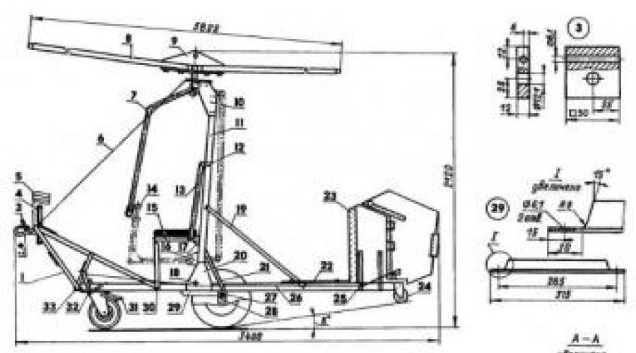
Gyrocopter layout:
1 - farm; 2 - towing hook; 3 - clip for fastening the towing hook (D16T); 4 - airspeed indicator; 5 - lateral drift indicator; 6 - tension (steel cable 02); 7 - control handle; 8 - main rotor blade; 9 - main rotor rotor head; 10 - rotor head bracket (D16T, sheet s4, 2 pcs.); 11 - mast (D16T, pipe 50x50x3); 12 - seat back mounting bracket (aluminum, sheet s3, 2 pcs.); 13 - seat back; 14 - “aircraft” version of the control stick; 15 - seat frame; 16 - bracket for the “aircraft” control stick; 17 - seat mounting bracket; 18.25 - control cable rollers (4 pcs.); 19 - strut (D16T, corner 30x30, 2 pcs.); 20 - mast mounting bracket (D16T, sheet s4, 2 pcs.); 21 - upper brace (steel, angle 30x30, 2 pcs.); 22 - horizontal tail; 23 - vertical tail; 24 - tail wheel; 26 - left branch of control wiring (cable 02); 27 - axial beam (D16T, pipe 50x50x3); 28 - side wheel axle mounting unit; 29 - lower brace (steel, angle 30x30.2 pcs.); 30 - seat support (D16T, corner 25x25, 2 pcs.); 31 - brake device; 32 - pedal assembly; 33 - keel beam (D16T, pipe 50x50x3)
In the middle of the keel beam there is a mast and a pilot's workplace - a seat with car seat belts. The mast is attached to the beam by two duralumin plate brackets at a slight angle back to the vertical and serves as the base for the rotor of a two-blade main propeller. The rotor mechanism is also connected to the mast by similar plate brackets. The screw rotates freely and unwinds due to the oncoming air flow. The rotor axis can be tilted in any direction using a handle, conventionally called a “delta handle,” with which the pilot adjusts the position of the gyroplane in space. This control system is the simplest, but differs from the standard one used on the vast majority of aircraft in that when the handle moves away from you, the gyroplane does not descend, but, on the contrary, gains altitude.
If desired, it is also possible to install an “aircraft” control stick (it is shown in dashed lines in the figure). The design naturally becomes more complicated. However, it is necessary to choose the type of control before building the gyroplane. The modification is unacceptable, since the piloting skills acquired with a “glitch” stick may give an undesirable result when switching to an “airplane” stick.
In addition, when moving on the ground, the pilot controls the nose wheel with his feet, and after takeoff, when the tail becomes effective as speed increases, he also controls the nose wheel with his feet and rudder. In the first case, he steers by alternately pressing his right or left foot on the corresponding shoulder of the cross member of the brake device on the wheel; in the second - to one or another pedal connected by cable wiring to the rudder.
The braking device is used during the run when landing on the runway. It is also not particularly difficult. The pilot presses the friction clutch (or simply a wooden board) against the wheel tire with his heels, causing them to rub against each other and thereby dampen the speed of the aircraft. As simple and cheap as possible!
The low weight and dimensions of the gyroplane allow it to be transported even on the roof of a car. The propeller blades are then disconnected. They are installed at their workplace immediately before the flight.
FRAME MANUFACTURING
As already mentioned, the basis of the gyroplane frame is the keel and axial beams and the mast. They are made of duralumin pipe with a square section of 50x50 mm with a wall thickness of 3 mm. Similar profiles are used in the construction of windows, doors, shop windows and other building elements. It is possible to use box beams made of duralumin corners connected by argon-arc welding. The best material option is D16T.
All holes in the beams were marked so that the drill only touched the inner walls without damaging them. The diameter of the drill was selected so that the MB bolts fit into the holes as tightly as possible. The work was carried out exclusively with an electric drill - using a manual one for these purposes is undesirable.

Most of the holes in the frame parts are coordinated in the drawings. However, many of them were drilled in place, as, for example, in the plate brackets connecting the keel beam to the mast. First, the right bracket, screwed to the keel beam, was drilled through the holes in the base of the mast pressed to it, then the left bracket was screwed on and also drilled, but through the finished holes of the right bracket and mast.
By the way, in the layout drawing it is noticeable that the mast is slightly tilted back (for this purpose, its base was beveled before installation). This is done so that the main rotor blades have an initial angle of attack of 9° on the ground. Then, even at a relatively low towing speed, a lifting force appears on them, the propeller begins to rotate, lifting the gyroplane into the air.
The axial beam is located across the keel and is attached to it with four Mb bolts with locked split nuts. In addition, the beams are connected by four angle steel braces for greater rigidity. Wheel axles (suitable for a scooter or motorcycle) are attached to the ends of the axle beam with paired clips. The wheels, as already mentioned, are scooter wheels, with bearings sealed to prevent dust and dirt from getting into them with caps from aerosol cans.
The frame and back of the seat are made of duralumin pipes (parts from children's cots or strollers are very suitable for this). At the front, the frame is attached to the keel beam with two duralumin corners 25x25 mm, and at the back - to the mast with a bracket made of steel corner 30x30 mm. The back, in turn, is screwed to the seat frame and also to the mast.
The seat frame is fitted with rings cut from the rubber inner tube of a truck wheel. A foam rubber cushion covered with durable fabric is placed on top of them and tied with ribbons. A cover made of the same fabric is placed on the back.
The front landing gear is a sheet steel fork with a kart wheel that rotates around a vertical axis. The axis is a short M12 bolt inserted into the hole of the sole (a rectangle made of steel sheet), which is attached to the keel beam from below with four Mb bolts. An additional round hole is cut in the keel beam for the head of the axle bolt.
A brake device is pivotally suspended from the sides to the fork stays of the nose wheel. It is assembled from a tubular cross member, two corner stringers and a wooden clutch. Let me remind you that the protruding ends of the crossbar allow the pilot to turn the steering wheel with his feet.
In the initial position, the device is held by two cylindrical tension springs, hooked to the brackets on the nose of the keel beam, and by a cable passed through the holes in the friction board. The springs are adjusted so that, in the absence of pilot control actions, the wheel is in the plane of symmetry of the gyroplane.

The pedal unit for controlling the aerodynamic rudder in the air is also quite simple. Both pedals, together with the parts riveted to them, are connected by hinge bolts to a pipe that is screwed to the angle on the keel beam. At the top of the pedals are attached sections of cable that stretch to the rudder hogs on the keel. The control wiring has four guide rollers, the design of which prevents the cables from falling out of them. The tension of the cables is maintained by coil springs attached to the pedals and a plate bracket on the keel beam. The springs are adjusted so that the rudder is in the neutral position.

The design of the truss is described in some detail above. Therefore, I will focus on what is mounted on the farm - on homemade aeronautical instruments, or rather, on one of them - the airspeed indicator. This is a glass tube open at the top, in which a lightweight plastic ball is placed. At the bottom it has a calibrated hole directed towards the flight of the gyroplane. The oncoming air flow causes the ball to rise in the tube, and its position determines the airspeed. You can calibrate the indicator by placing it out the window of a moving car. It is important to accurately plot the speed values in the range from 0 to 60 km/h, since these are the values that are important during takeoff and landing.
The horizontal tail is made of sheet duralumin 3 mm thick. The tail has two slots for duralumin corner struts to support the mast. At the points where the empennage is bolted to the keel beam, pads are riveted to the stabilizer to increase the rigidity of the connection.

The vertical tail is more complicated. It consists of a fin and rudder cut from multi-layer plywood: the first from 10 mm, the second from 6 mm. The individual edges of these parts are edged with thin steel tape. The keel and rudder are connected to each other by three card loops (on the left side).

Two counterweights weighing 350 g each are attached to the aerodynamic rudder horn with a through bolt MB (they are needed to eliminate the flutter phenomenon).
The trimmer on the trailing edge of the handlebar is made of soft sheet aluminum. By bending this plate to the right or left, you can adjust the accuracy of the steering wheel.
On both sides of the steering wheel there are screwed hogs, curved from a steel sheet. The heading control wiring cables are attached to them.
The vertical tail is attached to the keel beam on the right and, for greater rigidity, is reinforced with two brackets made of 25x25 mm duralumin corners.

At the end of the keel beam there is a tail wheel (from roller skates). It protects the vertical tail from damage if the gyroplane accidentally tips over on its tail, as well as during takeoff or landing with the nose too high.
RECOMMENDATION:
preliminary check of the gyroplane on the ground
You have assembled a gyroplane. Before you start making the rotor, check how the ready-made mechanisms work. It is best to do this at the site from which the gyroplane is supposed to fly.
Sit on the seat and make sure you are sitting comfortably and can reach the pedals with your feet. If necessary, place an additional pillow under your back. Jump on the seat - the cushion should not allow your body to touch the frame.
Tilt the nose wheel with your feet and watch the springs return it to the neutral position. Make sure that in this position the springs are not too tight, but not too loose. There should be no play in all connections.
Attach the gyroplane with a cable no more than ten meters long to the car and taxi at a speed of no more than 20 km/h. Warn the driver not to suddenly brake or reduce speed suddenly.
Remove your feet from the braking bar and see if the gyroplane maintains a straight line. Otherwise, adjust the spring tension. Learn to automatically find with your hand the cord for opening the hook and releasing the tow rope.
The main rotor rotor, located at the top of the mast, is the most complex component in the design of a gyroplane. The life of the pilot, no exaggeration, depends on the quality of workmanship, precision of assembly and error-free operation. The main materials for the parts of this assembly are D16T duralumin and ZOKHGSA steel (all duralumin parts are anodized, steel parts are cadmium-plated).
The rotor housing is perhaps the most important part, since in flight it is on the housing lugs that the entire structure of the gyroplane hangs. The housing itself houses two bearings - radial and angular contact, generously lubricated with grease. The housing with bearings rotates on the rotor axis. At the top of the axle there is a cottered slotted nut M20x1.5 (it should be noted that there are no simple nuts in the design of the gyroplane: the most important of them are cottered, the rest are self-locking). A blind cover hiding the axle nut protects the bearings from dust and moisture penetrating into them.
At the bottom, the rotor axis is fixedly connected to the control stick of the gyroplane. By moving the handle, you can change the position of the rotor in space, since the articulated connection of the axle with the axle and the axle with its body allows the deflection of the axis within the limits dictated by the diameter of the limiter hole.
The rotor is bolted to the top of the mast using two plate brackets.
RECOMMENDATION:
checking the alignment of the gyroplane
When the rotor head is ready and installed on the gyroplane, it is necessary to check the alignment of the gyroplane. Insert a bolt into the ears of the rotor housing, which will secure the rotor head with the main rotor blades, and hang the gyroplane by this bolt, for example, on a strong tree branch.

Sit on the seat and grasp the control handle. Keep it neutral. Have an assistant determine the position of the gyroplane mast. It should be tilted forward at an angle within 2-6° (ideally 4°). This check, usually called weight balancing, must be repeated whenever the weight of the pilot or gyroplane changes. In all cases, you cannot fly without such a check.
If the specified angle is outside the permitted range, then either move the pilot or add a small amount of ballast to the tail. But if there has been a significant change in the mass of the pilot (it exceeded 100 kg) or an engine is installed on the gyroplane, then it is necessary to make new, thicker plate brackets that hold the rotor at the top of the mast.
The main rotor blades are completely identical, so it is enough to describe the manufacturing process of only one of them.
Along the entire working length of the blade, its cross-sections are the same; no twisting or changing of geometric parameters is provided. This greatly simplifies things.

The best material for the frontal part of the blade is delta wood, which was used in aviation and maritime affairs. If this is not available, you can make an analogue yourself by gluing thin sheets of plywood with fiberglass gaskets with epoxy resin. Aviation plywood 1 mm thick is suitable for such a substitute. Since plywood sheets of the length required for the manufacture of blades are not produced, it is possible to glue together plywood strips cut to length. The joints in adjacent sheets should not be located one above the other, they must be spaced apart.
It is better to glue on a flat surface, placing a plastic film to which epoxy glue does not stick. You need to dial a total thickness of 20 mm. After applying the glue, the entire “pie” of the future blade should be pressed down with some long and even object with a weight and left to dry completely for a day. In terms of its mechanical properties, the resulting composition is no worse than real delta wood.
The specified profile of the leading edge (toe) of the spar is obtained using a template in the following way. Along the entire span of the spar, with a pitch of 150-200 mm, grooves are made in the leading edge until the template fits completely into the spar. The wood between the grooves is planed to make a ruler.
In the rear edges of the spar, using a planer (you can use scrapers), “quarters” 10 mm wide and 1 mm deep were selected under the plywood sheathing. The sheet of the lower skin (flush with the spar) is glued with epoxy resin, and to it and the spar are sheets of PS-1 foam plastic, which are pre-planed to a height of 20 mm. The foam layer is given the required shape according to the template of the top of the blade profile. A pine strip was used as the trailing edge. The top skin was glued last: it was enough to press it with clamps to the “quarter” of the spar and the trailing edge - and the sheet of plywood itself took the desired shape (the trailing edge of the blade should be slightly bent upward, as shown in the figure).
Each blade has a 100 g weight mounted in a fairing on the leading edge and a deflection trimmer on the trailing edge. In the butt part of the blade, steel linings are riveted, through which holes are drilled in the spar to attach the blade to the rotor head.
RECOMMENDATION:
balancing and tuning of blades
"After fabrication and painting, the blades need to be adjusted. Give this operation the utmost attention. Keep in mind that the cleaner and smoother the surfaces of the blades, the more lift they will create, and the gyroplane will be able to take off at a lower speed.
Attach the blades to the rotor head and check the balancing. If one of the blades turns out to be heavier and its end drops lower, then drill out part of its lead weight, ensuring that the blades are even. If this operation does not produce results (no more than 50 g can be removed), then drill several shallow holes in the thickest section of the light blade profile and fill them with lead.
Since the tips of the blades rotate at a peripheral speed of about 500 km/h, it is very important that they rotate in the same plane. Apply two different colored plastic strips to the leading edges at the very end of the blades. On a windy day, choose a place where the wind is constantly blowing at a speed of about 20-30 km/h (check with an airspeed indicator) and place the gyroplane against the wind. Tie it with a five-meter rope to a stump or stake firmly driven into the ground.
Sit on the seat, tie yourself with straps and, together with the gyroplane, back away so that the rope is taut. Holding the control handle with your left hand, place the rotor in a horizontal position, and with your right hand, spin the blades as hard as you can. Your assistant should watch from the side the rotation of the ends of the rotor.
Gradually tilt the rotor back and let it spin in the wind to a higher speed. If the multi-colored stripes rotate in the same plane, the blades have the same pitch. If you feel the glider shaking or an assistant shows that the blades are not rotating in the same plane, then immediately unload the rotor by moving it to a horizontal position or even tilting it forward. By bending the trimmers at a slight angle down or up, achieve the correct rotation of the blades.
As the rotor speed increases, the glider will rock and the front wheel will rise. In this case, the rotor will be tilted back, which will lead to even more intense spinning. Place your feet on the ground and control the position of the gyroplane in space. If you feel that it is taking off, immediately unload the rotor by pulling the control stick towards you. Having practiced this way, you will soon be ready for your first flight.
DIY gyroplane video
FLIGHT PRACTICE
Since not only the pilot, but also the driver of the car participates in the flight, there must be complete interaction between them. It is best if, in addition to the driver, there is another person in the car who can monitor the flight and receive all the pilot’s signals (decrease or increase in speed, etc.).
Before flights, check the technical condition of the gyroplane again. At first, use a relatively short tow rope no more than 20 m long. Be sure to warn the driver that they should accelerate smoothly and never brake sharply.
Position the gyroplane against the wind. Spin the rotor with your right hand and wait until it begins to gain speed due to the air pressure. If the wind is light, then give the driver the command to move at a speed of 10-15 km/h using the airspeed indicator. Continue to help the rotor with your hand as long as you can.
As you accelerate, tilt the rotor all the way back and give the driver a signal to increase the speed to 20-30 km/h. While steering the nose wheel, follow the vehicle in a straight line. When that wheel leaves the ground, move your feet to the pedals. By manipulating the control stick, maintain the position of the gyroplane so that it moves only on the side wheels, without touching the ground with either the nose or tail. Wait for the increased airspeed to lift the gyroplane into the air in this position. Adjust the flight altitude by longitudinal movements of the control stick (the rudder is not effective, since the glider is towed on a cable). During flight, do not allow any slack in the tow rope. Do not make turns at high speed.
Before landing, align yourself behind the vehicle until it reaches the end of the runway. Smoothly tilt the rotor forward and fly at an altitude of about a meter. Maintain this position with small “twitches” of the control handle. (In general, unlike controlling an airplane, on a gyroplane the movements of the sticks should not be smooth, but sharp, literally jerky.)
Signal the driver to slow down. When it does this, tilt the rotor all the way back. The rear wheel of the gyroplane should touch the ground first. Keep the rotor tilted back to prevent slack in the tow rope. When you stop, let the car turn around and move with it to the starting point. Keep the rotor positioned so that it continues to rotate. If there are no more flights, then place the rotor horizontally and, when the rotation speed decreases, stop it by hand. Never leave your seat while the rotor is spinning, otherwise the gyroplane may fly away without you.
Gradually, as you master your piloting technique, increase the length of the tow rope to one hundred meters and rise to a greater height.
The last stage of mastering the flight on a gyroplane will be free flight after uncoupling from the tow rope. Do not under any circumstances reduce the airspeed below 30 km/h in this mode!
From a height of 60 m, the free flight range can reach 300 m. Learn to make turns and rise to great heights. If you start from a hill, the flight range can be kilometers.
In recent years, aviation enthusiasts from many countries have shown great interest in flying homemade gyroplanes and gyroplanes themselves. Inexpensive, easy to manufacture and easy to pilot, these aircraft can be used not only for sports, but also as an excellent means of introducing wide circles of young people to the elements of air. Finally, they can be successfully used for communication. In the 1920s – 1940s, gyroplanes were built in many countries. Now they can only be seen in museums: they could not stand the competition with helicopters. However, for sporting purposes, gyroplanes and especially towed gyroplanes are still used today (see figure).
In our country, the design and construction of microgyroplanes is mainly carried out by student design bureaus of aviation universities. The best cars of this class were exhibited at exhibitions of technical creativity of young people, etc. Readers of “Modelist-Constructor” ask in numerous letters to tell us about the design of gliders-gyroplanes and micro-gyroplanes. This issue was at one time quite well covered on the pages of the magazine by the master of sports G.S. Malinovsky, who even in the pre-war years took part in experimental work with industrially built gyroplanes.
Essentially, this article is still relevant because it touches on an interesting area of technical creativity where aviation enthusiasts can and should achieve great success. The article does not at all claim to be an exhaustive coverage of the issue. This is just the beginning of a big conversation.
THE CONVERSATION STARTS WITH A “FLY”
Everyone knows the flying toy known as the Fly. This is a main rotor (propeller) mounted on a thin stick. As soon as you spin the stick with your palms, the toy itself breaks out of your hands and quickly flies up, and then, smoothly rotating, falls to the ground. Let's understand the nature of its flight. “Mukha” took off because we spent a certain amount of energy on its promotion - it was a helicopter (Fig. 1).


Now let’s tie a 3-5 m long thread to the stick on which the rotor is mounted and try to pull the “Fly” against the wind. It will take off and, under favorable conditions, spin quickly and gain altitude.
This principle is also inherent in the gyroplane: during the take-off run along the runway, its main rotor, under the influence of the oncoming flow, begins to unwind and gradually develops a lifting force sufficient for take-off. Consequently, the main rotor - the rotor - performs the same role as the aircraft wing. But, compared to a wing, it has a significant advantage: its forward speed with equal lifting force can be much less. Thanks to this, the gyroplane is able to descend almost vertically in the air and land on small areas (Fig. 2). If, during takeoff, you spin the rotor blades at a zero angle of attack, and then sharply move them to a positive angle, then the gyroplane will be able to take off vertically.

WHAT DID J. BENSEN FLY ON?
The prototype of most amateur gliders-gyroplanes was the car of the American I. Bensen. It was created shortly after the end of World War II and aroused great interest in many countries. According to official data, over several thousand devices of this kind have currently been built and are successfully flying.
The gyroplane of I. Bensen consists of a cross-shaped metal frame A, on which a pylon B is rigidly mounted, serving as a support for the rotor B with a direct control lever G. In front of the pylon there is a pilot’s seat D, and on the back of the frame there is a simple vertical tail, consisting of a keel E and a rudder direction G. The latter is connected by cables to a foot pedal located in the front part of the frame. The gyroplane chassis is three-wheeled, with lightweight pneumatic tires (the side wheels have a size of 300×100 mm, the front, steering wheel – 200×75 mm). Under the rear part of the frame there is an additional support wheel made of hard rubber with a diameter of 80 mm. The rotor has a metal hub and two wooden blades describing a circle with a diameter of 6 m. The chord of the blade is 175 mm, the relative thickness of the profile is 11%, the material is high-quality wood, glued with plywood and reinforced with fiberglass. Flights of the Bensen glider-gyroplane were carried out in tow behind a car (Fig. 5). Subsequently, a 70-horsepower engine with a pusher propeller was installed on similar machines.


Polish designers Alexander Bobik, Czeslaw Yurka and Andrei Sokalsky created a glider-gyroplane (Fig. 4) that takes off from the water. It was towed by a speedboat or motorboat with a powerful outboard motor (about 50 hp). The glider is mounted on a float, similar in shape and design to the body of a junior sports scooter. The directly controlled rotor is mounted on a simple and lightweight pylon, braced with cable braces to the float body. This made it possible to achieve a minimum weight of the structure with sufficient reliability. The technical data of the glider-gyroplane, which its authors called a “viroglider,” are as follows: length - 2.6 m, width - 1.1 m, height -1.7 m, total weight of the structure - 42 kg, rotor diameter - 6 m. Its flight data: takeoff speed - 35 - 37 km/h, maximum permissible - 60 km/h, landing - 15 - 18 km/h, rotor speed - 300 - 400 rpm.
Polish designers made many successful flights on their “viroglider”. They believe that their car has a great future. One of the creators of the “viroglider”, Cheslav Yurka, wrote: “If basic rules of caution and high discipline of the boat driver and maintenance personnel are observed, flights on “virogliders” are completely safe. A large number of lakes, the water surface of which is always free, will allow everyone to engage in this exciting sport and recreation.”
CONTROL SYSTEM
Let's figure out how the car's controllability is ensured. On an airplane it is simple - there are elevators, a rudder and ailerons. By deflecting them in the right direction, any evolutions are carried out. But rotorcraft, it turns out, do not need such rudders: a change in flight direction occurs immediately as soon as the rotor axis changes its position in space. To change the inclination of the rotor axis on the glider-gyroplane, a device consisting of two bearings is used; fixedly fixed in the cheeks of head A and connected to control lever B. Bearing A, being spherical, allows the rotor shaft to deviate from the main position by 12° in any direction, which provides the machine with longitudinal and lateral controllability.
The rotor control lever, rigidly connected to the lower bearing housing, has a crossbar resembling a bicycle handlebar, which the pilot holds with both hands. For takeoff, to move the rotor to a large angle, the lever moves forward; to reduce the angle and move the machine into horizontal flight - backwards; to create a roll to the right (or eliminate a left roll), the lever is deflected to the left, with a right roll - to the right. This feature of controlling gyroplanes creates certain difficulties for pilots flying conventional gliders, airplanes and helicopters (the handle movements of all these machines are directly opposite in sign).
Therefore, before flying on gyroplanes with direct control, it is necessary to undergo special training on a simulator. You can, however, go for some complication of the design by equipping the machine with “normal” aircraft-type controls (shown by the dotted line on the diagram of the Bensen gyroplane, see Fig. 3),
BEFORE YOU BUILD
A glider-gyroplane has significantly fewer parts than a regular bicycle. But this does not mean that it can be made somehow, tying it with wire in one place, and inserting a nail instead of a bolt in another.
All parts must be manufactured, as they say, at the highest aviation level: after all, human life depends on their quality and reliability. Even if you fly over water. Therefore, we must immediately make the following decision: if it is possible to carry out all the work with high quality, we will build a viroglider; if not, we will postpone construction until better times.


The most important and difficult part in the manufacture of a viroglider is, of course, the rotor. Attempts to use used blades from helicopters produced by our industry for installation on homemade gyroplanes were not successful, since they are designed for other modes. Therefore, they should not be used under any circumstances. A typical blade design is shown in Figure 6. To glue the spar, you need to prepare straight-layer, well-dried pine slats and carefully joint them together. They are collected in a package, as shown in Figure 7. Strips of ASTT6 grade fiberglass, pre-coated with epoxy glue, must be placed in the spaces between the slats. The slats should also be coated on both sides. After the necessary exposure, the package is pressed into a device that ensures straightness of the product along both the wide and narrow sides of the package. After drying, the package is processed in accordance with a given profile, forming the front part (“nose”) of the blade. The processing must be done very carefully, using steel counter-templates. The “tail” of the blade is made of polystyrene foam blocks of PCV-1 or PS-2 grade, reinforced with a number of plywood ribs. Gluing should be done in a special slipway (Fig. 8) to ensure the correct profile. The final processing of the blade is carried out with a file and sandpaper, using counter-patterns, after which the entire blade is covered with thin fiberglass cloth with epoxy glue, sanded, painted in a bright color and polished first with pastes and then with polishing water.
The finished blade, placed at its ends on two supports, must withstand at least 100 kg of static load.
To connect to the rotor hub, steel plates are secured on each blade with six M6 bolts, as shown in the drawing; in turn, these plates are attached to the hub with two M10 bolts. Trimmer D and counterweight G are installed on a fully finished blade. The weight is on three M5 bolts, the trimmer is on five rivets with a diameter of 4 mm. A wooden boss is glued in advance between the plywood ribs into the “shank” of the blade for riveting the trimmer.
The spherical bearing of the rotor head on foreign designs is selected ranging from a diameter of 50x16x26 mm to a diameter of 52x25x18 mm; Among domestic bearings of this type, No. 126 GOST 5720-51 can be used. In the diagram (Fig. 4) this bearing is shown as a single-row bearing for clarity. Lower control bearing – No. 6104 GOST 831-54.


A – base; B – hook; B – installation of the lock on the glider-gyroplane (hook down); D – installation of the lock on the towing boat (hook up)


Extreme simplicity of design is a characteristic feature of I. Bensen’s gyroplanes

Fastening the control lever to the bearing housing can be done with brackets, as shown in Figure 4 (this allows the entire assembly to be disassembled into individual elements), or by welding.
The base (“heel”) of the pylon is attached in the float body to a stiffening rib connected by four M6 bolts to the keel. These bolts simultaneously secure the outer metal feather to the float body. It is advisable to tighten the guy ropes connecting the pylon with the sides of the float before braiding with a force of 150 - 200 kg. Thunderbolts are aircraft grade, with threaded rods 5 mm thick.
As mentioned above, the weight of the viroglider must be kept within the range of 42 – 45 kg. It's not as simple as it seems at first glance. It is necessary to very carefully select the necessary materials, carry out processing and assembly correctly, and not use heavy putties and paints. This is especially true for the manufacture of a float. Its wooden frame should be assembled from well-dried slats of straight-grained, light (not resinous) pine. The best wood for making a float frame is the so-called “aviation” pine in fire monitors, but it is not available everywhere and cannot always be obtained. Therefore, one should not neglect possible substitutes: for example, a good container board or slats sawn from a thick slab (slab is the sapwood, the strongest part of the trunk; when properly sawed, it produces excellent slats of the desired section). Quite often, canned food is packed in good boxes. Having collected two or three dozen of these container boards, you can choose from them what you need for your work. Each rail must be tested for strength before being installed in place. If it breaks, it doesn’t matter, you can install another one; but you will have full confidence that the set is made of reliable material.
G. MALINOVSKY
As a child, a child is always asked – who does he want to be? Of course, many answer that they want to be pilots or astronauts. Alas, with the advent of adulthood, childhood dreams evaporate, family is a priority, making money and realizing a child’s dream fades into the background. But if you really want to, you can feel like a pilot - albeit for a short time, and for this we will construct a gyroplane with our own hands.
Any person can make a gyroplane; you just need to have a little understanding of technology, a general understanding will suffice. There are many articles and detailed manuals on this subject; in the text we will analyze gyroplanes and their design. The main thing is high-quality autorotation during the first flight.
Autogyroplanes - assembly instructions
An autogyroplane rises into the sky with the help of a car and a cable - a design similar to the flying kite that many, as children, launched into the sky. The flight altitude is on average 50 meters, when the cable is released, the pilot on the gyroplane is able to glide for some time, gradually losing altitude. Such short flights will give you a skill that will be useful when controlling a gyroplane with an engine; it can gain altitude up to 1.5 km and a speed of 150 km/h.
Autogyros - the basis of the design
For flight, you need to make a high-quality base in order to mount the remaining parts of the structure on it. Keel, axial beam and mast made of duralumin. In front is a wheel taken from a racing kart, which is attached to the keel beam. FROM two sides of scooter wheels, screwed to the axle beam. A truss is installed on the keel beam in front, made of duralumin, used to release the cable when towing.

There are also the simplest air instruments - a speed and lateral drift meter. Under the dashboard there is a pedal and a cable from it that goes to the steering wheel. At the other end of the keel beam there is a stabilizing module, rudder and safety wheel.
- Farm,
- towbar mounts,
- hook,
- air speedometer,
- cable,
- drift indicator,
- control lever,
- rotor blade,
- 2 brackets for the rotor head,
- rotor head from the main rotor,
- aluminum bracket for fastening the seat,
- mast,
- back,
- control knob,
- handle bracket,
- seat frame,
- control cable roller,
- bracket for fastening the mast,
- strut,
- upper brace,
- vertical and horizontal tail,
- safety wheel,
- axial and keel beam,
- fastening the wheels to the axle beam,
- lower brace from a steel angle,
- brake,
- seat support,
- pedal assembly.
Autogyros - the process of operation of a flying vehicle
The mast is attached to the keel beam using 2 brackets; near it there is a pilot’s seat - a seat with safety straps. A rotor is installed on the mast, it is also attached with 2 duralumin brackets. The rotor and propeller rotate due to the air flow, thus producing autorotation.

The glider control stick, which is installed near the pilot, tilts the gyroplane in any direction. Autogyroplanes are a special type of air transport; their control system is simple, but there are also some peculiarities: if you tilt the handle down, instead of losing altitude, they gain it.
On the ground, gyroplanes are controlled using the nose wheel, and the pilot changes its direction with his feet. When the gyroplane enters autorotation mode, the rudder is responsible for control.
The rudder is a braking device bar that changes its axial direction when the pilot presses his feet on its sides. When landing, the pilot presses the board, which creates friction against the wheels and reduces speed - such a primitive braking system is very cheap.
Autogyros have a small mass, which allows you to assemble it in an apartment or garage, and then transport it on the roof of a car to the place you need. Autorotation is what needs to be achieved when designing this aircraft. It will be difficult to build an ideal gyroplane after reading one article; we recommend watching a video on assembling each part of the structure separately.
For many years, gyroplanes were considered very dangerous aircraft. Even now, 90% of those who fly believe that gyroplanes are deadly. The most popular saying about gyroplanes is: “They combine the disadvantages of airplanes and helicopters.” Of course this is not true. Autogyroplanes have many advantages.
So where does the opinion about the colossal danger of gyroplanes come from?
Let's take a short excursion into history. Autogyros were invented in 1919 by the Spaniard de la Cierva. According to legend, he was prompted to do this by the death of his friend on the plane. The cause of the disaster was a stall (loss of speed and loss of lift and controllability). It was the desire to design an aircraft that was not afraid of stalling that led him to the invention of the gyroplane. La Cierva's gyroplane looked like this:
Ironically, La Cierva himself died in the plane crash. True, passenger.
The next stage is associated with Igor Bensen, an American inventor who in the 50s came up with a design that formed the basis of almost all modern gyroplanes. If Sierva's gyroplanes were, rather, airplanes with an installed rotor, then Bensen's gyroplane was completely different:
As you can see, the tractor engine arrangement has changed to a pushing one, and the design has been radically simplified.
It was this radical simplification of the design that played an evil role with gyroplanes. They began to be actively sold in the form of kits (kits for self-assembly), made by “craftsmen” in garages, and actively flown without any instructions. The result is clear.
The mortality rate on gyroplanes has reached unprecedented levels (about 400 times higher than on airplanes - according to English statistics from the 2000s, it included ONLY Bensen-type gyroplanes, various types of homemade ones).
At the same time, the control and aerodynamic features of the gyroplane were not properly studied; they remained experimental devices in the worst sense of the word.
As a result, serious mistakes were often made during their design.
Look at this device:
It seems to be similar in appearance to modern gyroplanes, photographs of which I provided in the first post. It seems like it, but it doesn’t look like it.
Firstly, the RAF-2000 did not have a horizontal tail. Secondly, the engine's thrust line ran significantly above the vertical center of gravity. These two factors were enough to make this gyroplane a “death trap”
Later, largely thanks to the RAF disasters, people studied the aerodynamics of the gyroplane and found the "pitfalls" of it, it would seem. perfect aircraft.
1.Rotor unloading
. The gyroplane flies thanks to a freely rotating rotor. What happens if the gyroplane enters a state of temporary weightlessness (updraft of air, top of the barrel, turbulence, etc.)? The rotor speed will drop, and the lift force will drop along with it... It would seem that there is nothing wrong, because such states do not last long - a fraction of a second, a second maximum.
2. Yes, no problem, if not for the high draft line, which can lead to power somersault
(PPO - power push-over).
Yes, I drew this again;)) The figure shows that the center of gravity (CG) is located significantly below the thrust line and that air resistance (drag) is also applied below the thrust line. The result is, as they say in aviation, a diving moment. That is, the gyroplane tries to somersault forward. In a normal situation, it’s okay - the pilot won’t give it. But in a situation where the rotor is unloaded, the pilot no longer controls the device, and it remains a toy in the hands of powerful forces. And he tumbles. And this often happens very quickly and unexpectedly. I was just flying and enjoying the views, and suddenly BAM! and you are already falling down into an uncontrollable tin can with sticks. Without a chance to restore controlled flight, this is not an airplane or a hang-glider.
3. In addition, gyroplanes have other strange things. This PIO (pilot induced oscillations - longitudinal swing provoked by the pilot
). In the case of unstable gyroplanes, this is very likely. The fact is that the gyroplane reacts somewhat slowly. Therefore, a situation may occur in which the pilot creates a kind of “swing” - trying to dampen the vibrations of the gyroplane, he actually strengthens them. As a result, the up-and-down oscillations increase and the apparatus turns over. However, PIO is also possible on an airplane - the simplest example would be the well-known habit of novice pilots to fight the “goat” with sudden movements of the stick. As a result, the amplitude of the “goat” only increases. On unstable gyroplanes, this very swing is very dangerous. On stable ones, treatment is very simple - you need to drop the “handle” and relax. The gyroplane will return to a calm state on its own.
The RAF-2000 was a gyroplane with a very high thrust line (HTL, high thrust line gyro), the Bensen ones - with a low thrust line (LTL, low thrust line gyro). And they killed a lot, a lot, a lot of pilots.
4. But even these gyroplanes could be flown if not for another discovered thing - it turns out that gyroplanes handle differently than airplanes
! In the comments to the last post, I described the reaction to engine failure (handle it away). So, in several articles I read about the exact opposite!!! In a gyroplane, if the engine fails, you need to urgently load the rotor by pushing the handle OUT and REMOVING the gas. Needless to say, the more experienced an airplane pilot is, the more powerful the reflex sits in his subcortex: when he refuses, pull the stick away and turn the throttle to maximum. In a gyroplane, especially an unstable one (with a high line of thrust), such behavior can lead to that very forceful somersault.
But that's not all - gyroplanes have many different features. I don’t know all of them, because I haven’t completed the training course myself yet. But many people know that gyroplanes are not so fond of “pedals” during landing (sliding, with the help of which “airplanes” often “gain altitude”), do not tolerate “barrels” and much more.
That is, on a gyroplane it is vitally important learn from a competent and experienced instructor
! Any attempts to master a gyroplane on your own are deadly! That doesn’t stop a huge number of people around the world from building and constructing their own stools with a screw, mastering them on their own and regularly beating on them.
5. Deceptive simplicity
. Well, the ultimate pitfall. Gyrocopters are very easy and pleasant to control. Many people make independent flights on them after 4 hours of training (I took off on a glider at 12 o’clock; this rarely happens before 10 o’clock). Landing is much easier than on an airplane, the shaking is incomparably less - that’s why people lose their sense of danger. I think this deceptive simplicity has killed no less people than somersaults with swings.
The gyroplane has its own “flying envelope” (flight restrictions) that must be observed. Exactly as in the case of any other aircraft.
Games are not good:
Well, that's all the horrors. At some stage in the development of gyroplanes, it seemed that everything was over, and gyroplanes would remain the lot of enthusiasts. But the exact opposite happened. The 2000s became the time of a colossal boom in gyroplane manufacturing. Moreover, the boom of FACTORY gyroplanes, and not homemade and semi-homemade whales... The boom is so strong that in 2011, 117 gyroplanes and 174 ultra-light aircraft/glitters were registered in Germany (a ratio unthinkable back in the 90s). What’s especially nice is that the lshiders of this market, which has only recently emerged, demonstrate excellent security statistics.
Who are these new gyroplane heroes? What did they come up with to compensate for the seemingly enormous shortcomings of gyroplanes? More on this in the next episode;)
Hornet gyroplane drawings. 1997 – development date. The design uses an engine with a power of more than 45 horsepower. Any type of engine is used, for example: boat; motorcycle; snowmobile. In the event of engine failure, emergency independent rotation of the main rotor is activated, and landing is carried out, which ensures high pilot safety.

Technical characteristics of the gyroplane (the engine used on the model is Rotex 447):
- rotor (diameter), mm – 7320;
- propeller, mm – 152;
- height, mm – 2280;
- width, mm – 1830;
- lifting weight, t – 0.280;
Weight, t – 0.160;
- maximum speed, km/h – 102;
- operating speed, km/h – 80;
- tank capacity, l – 20;
- flight range, km – 90.

The gyroplane is kept in the air thanks to the rotor (carrying). The propeller is driven by the flow of oncoming air, and not by the engine. The horizontal movement of the structure is carried out by an additional screw mounted on the horizontal axis of rotation.
Gyroplane is another name for a flying structure. Not all gyroplane models can take off vertically. Most models require a runway no more than 30 meters long.