Calculation of the short circuit current of the ground loop. Calculation of protective grounding. Determination of soil resistivity
Read also
A protective circuit created around any object that is supplied with electricity will ensure that high voltage drains into the ground through specially installed electrodes. Such designs protect expensive equipment from short circuits and burnout due to power surges. The installation of the structure must be carried out in accordance with the results of the calculations of the level of electrical conductivity of the conductors.
Purpose of calculation
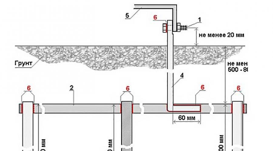
Before installing on a residential or other facility, it is necessary, its standard sizes. This design consists of:
- elements installed vertically to the ground;
- conductor;
- strips connecting the contour in the horizontal plane.
The electrodes are dug in and connected to each other using a horizontal ground electrode. After that, the created protection system is connected to the electrical panel.
Such artificial structures are used in power networks with different voltage indicators:
- variable from 380 V;
- constant from 440 V;
at hazardous production facilities.

Protective systems are installed in different places of the equipment. Depending on the installation location, they are remote or contour. In open structures, the elements are connected directly to the grounding element. In contour devices, the placement is along the outer perimeter or inside the device. For each type of protective installations, it is necessary to carry out a calculation in order to establish the resistance value of vertical grounding conductors, the number of required rods and the length of the strips for their connection.
In addition to special devices, natural systems can be used:
- communications from metal pipes;
- metal structures;
- substations;
- supports;
- metal cable sheath;
- casing.
Conductivity calculations are made for artificial structures. Their arrangement at the place of use of power plants ensures the removal of electric current to the ground, protecting people and equipment from large-scale discharges as a result of a power surge. The lower the electrical conductivity, the lower the level of electric current leaving through the protective structure.

Step-by-step calculation of the ground loop
Calculations should be carried out taking into account the number of elements, their distance from each other, the current conductivity of the soil and the depth of digging in the vertical ground electrode. Using these parameters, it will be possible to carry out an accurate calculation of protective earthing.
First, you should determine the type of soil from the table. After that, select the appropriate materials for the construction. Then calculations are carried out using special formulas that determine the number of all elements, as well as their ability to conduct electricity.
Based on the results obtained, the installation of the entire system is carried out, after which control measurements are carried out for its current conductivity.
Initial data
When calculating the force value, one should draw up the ratio of their number, the length of the connecting strips and the distance at which the digging is carried out.

In addition, it will be necessary to take into account the specific resistance of the soil, which is determined by the level of its moisture content. To achieve a stable value, it is necessary to bury the electrodes in the soil to a depth of at least 0.7 meters. It is also important not to deviate from the size of the protective device itself established by GOST. When carrying out the calculation, it is necessary to use ready-made tables with already available indicators for the materials used and the electrical conductivity of certain types of soils.
Table of indicators of electrical conductivity of various soils

The required depth to which a vertical electrode is buried in the ground is calculated by the formula:
When installing a protective structure, it is necessary to ensure that the metal rods are completely included in the upper layer of the earth and partially in its lower levels. During the calculations, it will be necessary to use the average coefficients of the level of electrical conductivity of the soil in different seasons in certain climatic zones, presented in this table:
Soil resistance in different climatic zones

To accurately determine the number of vertical elements in the assembled structure, without taking into account the indicators for narrow strips connecting them, you need to use the formula:
In it, Rн, denoting the strength of the current spreading over the soil of a certain type, the resistance coefficient for which is taken from the table.
To calculate the physical parameters of the material, the dimensions of the system elements used should be taken into account:
- for strips 12x4 - 48 mm2;
- at the corners 4x4 mm;
- for a steel circle - 10 mm2;
- for pipes whose walls are 3.5 mm thick.
Grounding calculation example

It is necessary to calculate the conductivity of the conductors used, taking into account the characteristics of the soil, for each electrode separately according to the formula:

Wherein:
- Ψ is the climatic coefficient, which is taken from the reference literature;
- ρ1, ρ2 - the value of the conductivity of the upper and lower layers of the earth;
- H is the thickness of the top layer of soil;
- t is the depth of the vertical element in the trench.
Rods for such structures are buried at a level of at least 0.7 meters, in accordance with current regulations.
What should we have at the end of the calculation
After carrying out calculations using the formulas used, it is possible to obtain the exact resistance of an artificial grounding device. It is often impossible to measure these indicators in natural systems due to the impossibility of obtaining the exact dimensions of buried communications, ruts, cables, or already installed metal structures.

Upon completion of the calculations, it is possible to obtain the exact number of rods and strips for the contour, which will help create a reliable protection system for the equipment used and the entire object as a whole. Calculations will also help to establish the exact length of the strips connecting the rods. The main result of all the calculations will be to obtain the final value of the properties of the conductors used in the created circuit, which determines the strength of the electric current passing through them. This is the most important PES standard, which has certain values for networks with different voltage indicators.
Permissible values of ground resistance, according to regulations
There are uniform normative values according to which the current spreading resistance for an electrical network with a certain voltage value should not exceed the established GOST standards. In networks with a voltage of 220 V, it should not exceed 8 ohms. At a voltage of 380 V, its value should not exceed 4 ohms.

To calculate the indicators of the entire circuit, you can use the formula R \u003d R0 / ηv * N, in which:
- R0 is the level of conductance for one electrode;
- R - indication of the level of obstruction to the passage of current for the entire system;
- ηv - coefficient of use of the protective device;
- N is the number of electrodes in the entire circuit.
Material required for the contour device
You can assemble the circuit from a metal material:
- corner,
- stripes with specific dimensions.
After it must be checked by an expert from an independent measuring laboratory. Building reinforcement can be used as a natural contour if it is present in the load-bearing structures of the building. PES contains a special list of structures that can be used as a natural contour when creating protective systems.
To check the operation of the entire structure, it is necessary to check the total value and resistance of vertical grounding conductors and the entire system with special devices. This work should be entrusted to independent experts from the electrical laboratory. In order for the structure to reliably protect the entire object, measurements should be taken regularly, checking their value to the established standards.
Rated resistance to current spreading into the ground (permissible for a given soil) Rated resistanceRated resistance to current spreading of the grounding device in accordance with the Electrical Installation Rules (PUE). Dimension - Ohm.
In accordance with the PUE, the permissible resistance of the grounding device Rn is established. If the grounding device is common for installations for different voltages, then the smallest of the allowable ones is taken as the design resistance of the grounding device.
The resistance of the grounding device to which the neutrals of the generator or transformer or the leads of a single-phase current source are connected, at any time of the year should be no more than 2, 4 and 8 ohms, respectively, at line voltages of 660, 380 and 220 V of a three-phase current source or 380, 220 and 127 In a single-phase current source. This resistance must be provided taking into account the use of natural grounding conductors, as well as grounding conductors for repeated grounding of a PEN or PE conductor of an overhead line with a voltage of up to 1 kV with a number of outgoing lines of at least two. The resistance of the ground electrode located in close proximity to the neutral of the generator or transformer or the output of a single-phase current source should be no more than 15, 30 and 60 Ohms, respectively, at line voltages of 660, 380 and 220 V of a three-phase current source or 380, 220 and 127 V of a single-phase current source current.
At line voltages of 660, 380 and 220 V of a three-phase current source or 380, 220 and 127 V of a single-phase current source in case the earth resistivity p> 100 Ohm * m it is allowed to increase the indicated norms by 0.01 p times, but not more than ten times.
Grounding devices of electrical installations with voltage up to 1 kV in networks with isolated neutral, used for protective grounding of open conductive parts in the IT system, must comply with the condition:
where R is the resistance of the grounding device, Ohm;
Upr - touch voltage, the value of which is assumed to be 50 V (see also 1.7.53 PUE);
I - total earth fault current, A.
As a rule, it is not required to accept the resistance value of the grounding device as less than 4 ohms. Grounding device resistance up to 10 Ohm is allowed if the above condition is met, and the power of generators or transformers does not exceed 100 kVA, including the total power of generators or transformers operating in parallel.
In electrical installations with a voltage above 1 kV of a network with an isolated neutral, the resistance of the grounding device during the passage of the rated earth fault current at any time of the year, taking into account the resistance of natural grounding conductors, should be
but not more than 10 Ohm, where I is the rated earth fault current, A.
The following is taken as the rated current:
1) in networks without compensation of capacitive currents - earth fault current;
2) in networks with compensation of capacitive currents:
for grounding devices to which compensating devices are connected - a current equal to 125% of the rated current of the most powerful of these devices; for grounding devices to which compensating devices are not connected - the earth fault current passing in this network when the most powerful of these devices is disconnected compensating devices.
The estimated earth fault current must be determined for the network scheme possible in operation, in which this current has the highest value.")" onmouseout="hide_info(this)" src="/pics/help.gif">
) for a single deep earth electrode based on modular grounding is made as a calculation of a conventional vertical ground electrode made of a metal rod with a diameter of 14.2 mm.
The formula for calculating the grounding resistance of a single vertical ground electrode:
where:
ρ - soil resistivity (Ohm*m)
L - earth electrode length (m)
d - earth electrode diameter (m)
T - earth electrode penetration (distance from the ground surface to the middle of the ground electrode)(m)
π - mathematical constant Pi (3.141592)
ln - natural logarithm
For ZANDZ electrolytic grounding, the formula for calculating the grounding resistance is simplified to the form:
- for set ZZ-100-102
The contribution of the connecting earth conductor is not taken into account here.
Distance between ground electrodes
With a multi-electrode configuration of the ground electrode, another factor begins to influence the final ground resistance - the distance between the ground electrodes. In the formulas for calculating grounding, this factor is described by the value "utilization factor".
For modular and electrolytic grounding, this coefficient can be neglected (i.e. its value is 1) subject to a certain distance between the ground electrodes:
- not less than the electrode immersion depth - for modular
- not less than 7 meters - for electrolytic
Connecting electrodes to the ground electrode
To connect the grounding electrodes to each other and to the object, a copper rod or a steel strip is used as a grounding conductor.
The conductor cross section is often chosen - 50 mm² for copper and 150 mm² for steel. It is common to use a conventional steel strip 5 * 30 mm.
For a private house without lightning rods, a copper wire with a cross section of 16-25 mm² is sufficient.
More information about laying the ground conductor can be found on a separate page "Installation of grounding".
Service for calculating the probability of a lightning strike into an object
If, in addition to the grounding device, you have to install an external lightning protection system, you can use the unique service for calculating the probability of a lightning strike into an object protected by lightning rods. The service was developed by the ZANDZ team together with the Energy Institute named after G.M. Krzhizhanovsky (JSC ENIN)
This tool allows not only to check the reliability of the lightning protection system, but also to carry out the most rational and correct design of lightning protection, providing:
- lower cost of construction and installation work, reducing unnecessary stock and using less high, less expensive to install, lightning rods;
- fewer lightning strikes into the system, reducing secondary negative consequences, which is especially important at sites with many electronic devices (the number of lightning strikes decreases with a decrease in the height of lightning rods).
- the probability of a lightning breakthrough into the objects of the system (the reliability of the protection system is defined as 1 minus the probability value);
- the number of lightning strikes into the system per year;
- the number of lightning breakthroughs, bypassing protection, per year.
Having such information, the designer can compare the requirements of the customer and regulatory documentation with the obtained reliability and take measures to change the design of lightning protection.
The grounding system ensures the safety of residents and the uninterrupted operation of electrical appliances. Grounding prevents electric shock in the event of electricity leaks to non-current-carrying metal elements that occur when the insulation is damaged. The creation of a security system is a responsible event, therefore, before it is carried out, it is necessary to calculate the grounding.
Natural ground
At a time when the list of household appliances in a home was limited to one TV, refrigerator and washing machine, grounding devices were rarely used. Protection against current leakage was assigned to natural grounding conductors, such as:
- uninsulated metal pipes;
- casing of water wells;
- elements of metal fences, street lamps;
- braiding of cable networks;
- steel elements of foundations, columns.
The best option for natural grounding is a steel water main. Due to their long length, water pipes minimize the resistance to spreading current. The effectiveness of water pipes is also achieved due to their laying below the level of seasonal freezing, and therefore neither heat nor cold affects their protective qualities.
Metal elements of underground concrete products are suitable for an earthing system if they meet the following requirements:
- there is sufficient (according to the norms of the Electrical Installation Rules) contact with a clay, sandy loam or wet sandy base;
- during the construction of the foundation, reinforcement in two or more sections was brought out;
- metal elements have welded joints;
- reinforcement resistance complies with the regulations of the PUE;
- there is an electrical connection with the ground bus.
Note! Of the entire list of the above natural groundings, only underground reinforced concrete structures are calculated.
The efficiency of the functioning of natural grounding is established on the basis of measurements carried out by an authorized person (representative of Energonadzor). Based on the measurements taken, the specialist will give recommendations on the need to install an additional circuit to the natural ground loop. If natural protection meets the requirements of the regulations, the Electrical Installation Rules indicate the inappropriateness of additional grounding.
Calculations for an artificial grounding device
It is almost impossible to make an absolutely accurate calculation of grounding. Even professional designers operate with an approximate number of electrodes and distances between them.
The reason for the complexity of the calculations is a large number of external factors, each of which has a significant impact on the system. For example, it is impossible to predict the exact level of humidity, the actual density of the soil, its resistivity, and so on are not always known. Due to the incomplete certainty of the input data, the final resistance of the organized ground loop ultimately differs from the base value.
The difference in the designed and actual indicators is leveled by installing additional electrodes or by increasing the length of the rods. Nevertheless, preliminary calculations are important, as they allow:
- refuse unnecessary expenses (or at least reduce them) for the purchase of materials, for earthworks;
- choose the most suitable configuration of the grounding system;
- choose the right course of action.
To facilitate the calculations, there is a variety of software. However, in order to understand their work, certain knowledge about the principles and nature of calculations is necessary.
Protection components
Protective grounding includes electrodes installed in the ground and electrically connected to the ground bus.
The system has the following elements:
- Metal rods. One or more metal rods direct the spreading current into the ground. Usually, pieces of long metal (pipes, angle, round metal products) are used as electrodes. In some cases sheet steel is used.
- A metal conductor that combines several grounding conductors into a single system. Usually, a horizontal conductor in the form of a corner, rod or strip is used in this capacity. A metal bond is welded to the ends of electrodes buried in the ground.
- A conductor that connects a ground electrode located in the ground with a bus that has a connection with the protected equipment.
The last two elements are called the same - the grounding conductor. Both elements perform the same function. The difference lies in the fact that the metal bond is located in the ground, and the conductor for connecting the ground to the bus is located on the surface. In this regard, conductors are subject to unequal requirements for resistance to corrosion.
Principles and rules of calculation
Soil is one of the constituent elements of the grounding system. Its parameters are important and are involved in the calculations in the same way as the length of metal parts.
When making calculations, the formulas specified in the Electrical Installation Rules are used. Variable data collected by the system installer and constant parameters (available in the tables) are used. Constant data include, for example, soil resistance.
Determination of a suitable circuit
First of all, you need to choose the shape of the contour. The design is usually made in the form of a certain geometric figure or a simple line. The choice of a specific configuration depends on the size and shape of the site.
The easiest way to implement a linear circuit, since for the installation of electrodes you need to dig only one straight trench. However, the electrodes installed in the line will be shielded, which will worsen the situation with the spreading current. In this regard, when calculating linear grounding, a correction factor is applied.
The most common scheme for creating protective grounding is the triangular shape of the circuit. Electrodes are installed along the tops of the geometric figure. The metal pins must be spaced far enough apart so as not to interfere with the dissipation of the currents flowing into them. Three electrodes are considered sufficient for arranging the protective system of a private house. To organize effective protection, it is also necessary to choose the right length of the rods.
Calculation of conductor parameters
The length of the metal rods is important because it affects the effectiveness of the protection system. The length of the metal bond elements also matters. In addition, the material consumption and the total cost of arranging grounding depend on the length of the metal parts.
The resistance of vertical electrodes is determined by their length. Another parameter - transverse dimensions - does not significantly affect the quality of protection. Nevertheless, the cross-section of conductors is regulated by the Electrical Installation Rules, since this characteristic is important from the point of view of corrosion resistance (electrodes should serve 5 to 10 years).
Subject to other conditions, there is a rule: the more metal products are involved in the circuit, the higher the safety of the circuit. Work on organizing grounding is quite laborious: the more grounding conductors, the more earthworks, the longer the rods, the deeper they need to be hammered.
What to choose: the number of electrodes or their length - the organizer of the work decides. However, there are certain rules about this:
- The rods must be installed below the seasonal freezing horizon by at least 50 centimeters. This will remove seasonal factors from influencing the efficiency of the system.
- Distance between vertically installed earthing switches. The distance is determined by the contour configuration and the length of the bars. To select the correct distance, you need to use the appropriate reference table.
Sliced metal is driven into the ground by 2.5 - 3 meters using a sledgehammer. This is a rather time-consuming task, even if we take into account that approximately 70 centimeters of trench depth must be subtracted from the indicated value.
Economical consumption of material
Since the metal section is not the most important parameter, it is recommended to purchase a material with the smallest sectional area. However, you must remain within the minimum recommended values. The most economical (but able to withstand sledgehammer blows) hardware options:
- pipes with a diameter of 32 mm and a wall thickness of 3 mm;
- equal-shelf corner (side - 50 or 60 millimeters, thickness - 4 or 5 millimeters);
- round steel (diameter from 12 to 16 millimeters).
As a metal bond, a strip of steel 4 mm thick will be the best choice. Alternatively, a 6mm steel bar will do.
Note! Horizontal rods are welded to the tops of the electrodes. Therefore, another 18 - 23 centimeters should be added to the calculated distance between the electrodes.
The outer grounding section can be made from a 4 mm strip (width - 12 mm).
Formulas for calculations
A universal formula is suitable, with the help of which the resistance of a vertical electrode is calculated.
When carrying out calculations, one cannot do without reference tables, where approximate values \u200b\u200bare indicated. These parameters are determined by the composition of the soil, its average density, the ability to retain water, and the climatic zone.
We set the required number of rods, not taking into account the resistance of the horizontal conductor.
We determine the resistance level of the vertical rod based on the resistance index of the horizontal type ground electrode.
Based on the results obtained, we acquire the required amount of material and plan to start work on creating a grounding system.
Conclusion
Since the highest soil resistance is observed in dry and frosty times, it is best to plan the organization of the grounding system for this period. On average, the construction of grounding takes 1 - 3 working days.
Before backfilling the trench with earth, the operability of the grounding devices should be checked. The optimal testing environment should be as dry as possible, with little moisture in the soil. Since winters are not always snowless, it is easiest to start building a grounding system in the summer.
Grounding is a valuable structure that protects the owners of home appliances from direct contact with a very useful, but extremely zealous flow of electricity. The grounding device will ensure safety in the event of zero “burning out”, which often happens on suburban power lines during heavy winds. It will eliminate the risk of damage from leaks to non-current-carrying metal parts and the case due to leaky insulation. The construction of a protective system is an event that does not require extra effort and super investments, if the grounding calculation is correctly made. Thanks to preliminary calculations, the future contractor will be able to determine the upcoming costs and the feasibility of the upcoming business.
To build or not to build?
In an already fairly forgotten time of a meager amount of household electrical appliances, owners of private houses rarely “dabbled” with a grounding device. It was believed that natural grounding conductors, such as:
- steel or cast iron pipelines, if no insulation is laid around them, i.e. there is direct close contact with the soil;
- steel casing of a water well;
- metal supports of fences, lanterns;
- lead braid of underground cable networks;
- reinforcement of foundations, columns, trusses buried below the seasonal freezing horizon.
Please note that the aluminum sheath of underground cable communications cannot be used as a grounding element, because. coated with an anti-corrosion layer. The protective coating prevents current dissipation in the ground.

The steel water pipe laid without insulation is recognized as the optimal natural grounding conductor. Due to the considerable length, the resistance to the spreading current is minimized. In addition, the external water supply is laid below the level of seasonal freezing. This means that frost and dry summer weather will not affect the resistance parameters. During these periods, soil moisture decreases, and, as a result, resistance increases.
The steel frame of underground reinforced concrete structures can serve as an element of the grounding system if:
- clayey, loamy, sandy loamy and wet sandy soil is in contact with a sufficient area according to the PUE standards;
- during the construction of the foundation, reinforcement in two or more places was brought to the surface;
- the steel elements of this natural earthing were interconnected by welding, and not by wire bonding;
- the resistance of the armature, which plays the role of electrodes, is calculated in accordance with the requirements of the PUE;
- an electrical connection to the ground bus is established.
Without compliance with the above conditions, underground reinforced concrete structures will not be able to perform the function of reliable grounding.

Of the entire set of the above natural grounding conductors, only underground reinforced concrete structures are subject to calculations. It is not possible to accurately calculate the current spreading resistance of pipelines, metal armor and channels of underground power networks. Especially if their laying was carried out a couple of decades ago, and the surface is significantly corroded.
The effectiveness of natural grounding is determined by banal measurements, for which you need to call an employee of the local energy service. The readings of his instrument will tell whether or not the owner of a suburban property needs a second ground loop as an addition to the existing grounding measures performed by the electricity supplier.

If there are natural grounding conductors on the site with resistance values \u200b\u200bcorresponding to the PUE standards, it is not advisable to arrange protective grounding. Those. if the energy management “agent” device showed less than 4 ohms, the organization of the ground loop can be postponed “for later”. However, it is better to play it safe and prevent possible risks, for which an artificial grounding device is being built.
Calculations for an artificial grounding device
It must be admitted that it is difficult, almost impossible, to thoroughly calculate the grounding device. Even among professional electricians, the method of approximate selection of the number of electrodes and the distances between them is practiced. Too many natural factors affect the result of work. The moisture level is unstable, often the actual density and resistivity of the soil, etc., have not been studied for certain. Because of what, in the end, the resistance of an arranged circuit or a single ground electrode system differs from the calculated value.
This difference is revealed by the same measurements and corrected by installing additional electrodes or by increasing the length of a single rod. However, preliminary calculations should not be abandoned, because they will help:
- eliminate or reduce additional costs for the purchase of material and digging branches of trenches;
- choose the optimal configuration of the grounding system;
- draw up a plan of action.
To facilitate difficult and rather confusing calculations, several programs have been developed, but in order to correctly use them, knowledge about the principle and procedure of calculations will be useful.

Components of the protective system
The protective grounding system is a complex of electrodes buried in the ground, electrically connected to the ground bus. Its main components are:
- one or more metal rods that transmit the spreading current to the ground. Most often, they are used as vertically hammered into the ground segments of long-length rolled metal: pipes, equal-shelf angles, round steel. Less commonly, the function of electrodes is performed by pipes or sheet steel horizontally buried in a trench;
- metal connection connecting a group of grounding conductors into a functional system. Often this is a horizontally located grounding conductor from a strip, angle or bar. It is welded to the tops of electrodes buried in the ground;
- a conductor connecting the grounding device located in the ground with the bus, and through it with the protected equipment.
The last two components are collectively called the "grounding conductor" and, in fact, perform the same function. The difference is that the metal connection between the electrodes is located in the ground, and the conductor connecting the ground to the bus is on the day surface. Hence the different requirements for materials and corrosion resistance, as well as the spread in their cost.

Principles and rules of calculation
The combination of electrodes and conductors, called grounding, is installed in the ground, which is a direct component of the system. Therefore, in the calculations, its characteristics are directly involved along with the selection of the length of artificial grounding elements.
The calculation algorithm is simple. They are produced according to the formulas available in the PUE, in which there are variable units that depend on the decision of an independent master, and constant tabular values. For example, the approximate value of soil resistance.
Determination of the optimal contour
A competent calculation of protective grounding begins with the choice of a contour that can repeat any of the geometric shapes or a regular line. This choice depends on the shape and size of the site available to the master. It is more convenient and easier to build a linear system, because only one straight trench will need to be dug to install the electrodes. But the electrodes located in one row will shield, which will inevitably affect the spreading current. Therefore, when calculating linear grounding, a correction factor is introduced into the formulas.
The most popular scheme for self-recognition is a triangle. The electrodes located at its tops, at a sufficient distance from each other, do not interfere with the current received by each of them to freely dissipate in the ground. Three metal rods for a private house protection device are considered quite sufficient. The main thing is to arrange them correctly: to drive metal rods of the required length into the ground at an effective distance for work.
Distances between vertical electrodes must be equal, regardless of the configuration of the earthing system. The distance between two adjacent bars should not be equal to their length.

Selection and calculation of parameters of electrodes and conductors
The main working elements of protective grounding are vertical electrodes, because they will have to dissipate current leakage. The length of the metal rods is interesting, both from the point of view of the effectiveness of the protective system, and from the point of view of the metal consumption and price of the material. The distance between them determines the length of the metal bond components: again, the material consumption to create grounding conductors.
Please note that the resistance of vertical earthing depends mainly on their length. The transverse dimensions do not significantly affect the efficiency. However, the size of the cross section is normalized by the PUE due to the need to create a wear-resistant protective system, the elements of which will gradually be destroyed by corrosion for at least 5-10 years.
We choose the optimal parameters, given that we do not need extra expenses at all. Do not forget that the more meters of rolled metal we drive into the ground, the more benefit we will get from the circuit. You can “gain” meters either by increasing the length of the rods, or by increasing their number. Dilemma: installing multiple ground electrodes will make you work hard as a digger, and manually hammering long electrodes with a sledgehammer will turn you into a strong hammer.
Which is better: the number or length, the direct performer will choose, but there are rules according to which it is determined:
- the length of the electrodes, because they need to be buried below the seasonal freezing horizon by at least half a meter. So it is necessary that the performance of the system does not suffer too much from seasonal factors, as well as from droughts and rains;
- distance between vertical grounding conductors. It depends on the configuration of the circuit and on the length of the electrodes. It can be determined from tables.
It is difficult and inconvenient to hammer pieces of rolled metal 2.5-3 meters into the ground with a sledgehammer, even taking into account the fact that 70 cm of them will be immersed in a pre-dug trench. The rational length of the grounding conductors is considered to be 2.0 m with variations around this figure. Do not forget that long pieces of rolled metal are not easy and very expensive to deliver to the site.

Smartly save on material
It has already been mentioned that little depends on the cross-section of rolled metal, except for the price of the material. It is wiser to buy material with the smallest possible cross-sectional area. Without lengthy discussion, we present the most economical and resistant to sledgehammer strikes options, these are:
- pipes with an inner diameter of 32 mm and a wall thickness of 3 mm or more;
- equal-shelf corner with a side of 50 or 60 mm and a thickness of 4-5 mm;
- round steel with a diameter of 12-16 mm.
To create an underground metal connection, a steel strip 4 mm thick or a 6 mm bar is best suited. Do not forget that the horizontal conductors need to be welded to the tops of the electrodes, therefore we will add another 20 cm to the distance between the rods we have chosen. The above-ground section of the grounding conductor can be made from a 4 mm steel strip 12 mm wide. You can bring it to the shield from the nearest electrode: you will have to dig less and save material.

And now directly formulas
We have decided on the shape of the contour and the dimensions of the elements. Now you can drive the required parameters into a special program for electricians or use the formulas below. In accordance with the type of grounding conductors, we select the formula for making calculations:

Or we use the universal formula for calculating the resistance of one vertical rod:

For calculations, auxiliary tables will be required with approximate values \u200b\u200bdepending on the composition of the soil, its average density, the ability to retain moisture and the climatic zone:

Let's calculate the number of electrodes, not taking into account the resistance value of the grounding horizontal conductor:

Let's calculate the parameters of the horizontal element of the grounding system - the horizontal conductor:

Let's calculate the resistance of the vertical electrode, taking into account the value of the resistance of the horizontal ground electrode:


According to the results obtained as a result of diligent calculations, we stock up on material and plan time for the grounding device.
In view of the fact that our protective grounding will have the greatest resistance during the dry and frosty period, it is advisable to start its construction at this time. With the right organization, it will take a couple of days to build the circuit. Before backfilling the trench, it will be necessary to check the operability of the system. This is best done when the soil contains the least amount of moisture. True, winter is not very conducive to work in open areas, and earthwork is complicated by frozen ground. This means that we will be engaged in the construction of a grounding system in July or early August.