Calculation of the visor for snow load. Collection of loads from snow. Snow bag. Farm from a profile pipe
In the article "How to determine the load on the roof in your area" we decided on the option of a classic gable roof. But very often there are situations when sheds are attached to the house, and not everyone knows that these sheds will be loaded with snow much more than the roof itself. When collecting loads from snow, there is such a thing as a snow bag. If there are height differences on the roof, or just a canopy adjacent to a high wall, then favorable conditions are created for snowdrifting in this place. And the higher the wall to which the roof adjoins, the greater the height of this snowdrift will be, and the greater the load will affect the supporting structures. Sometimes a snow bag is able to increase the standard snow load several times.
Let's analyze the situation with an example.
House with a gable roof. A canopy is attached to it on both sides. It is necessary to determine the snow load on 1 m 2 of the roof of the house and two sheds. Construction area - Kyiv region (160 kg / m 2).
1) Determine the snow load on the roof of the house.
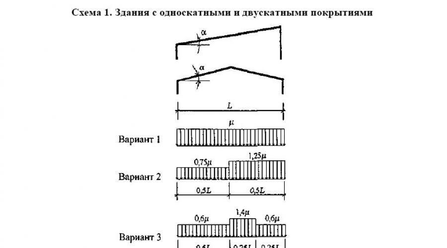
The slope of the roof is 35 degrees. Let's open scheme 1 of appendix G DBN V.1.2-2:2006 "Loads and impacts".

Because the slope of the roof does not fit into the range of 20-30 degrees, and there are no bridges with lanterns, then we need to take the load scheme according to option 1 - the same for the entire roof.
By interpolation we determine:
Se = γ fe S 0 C = 0,49*160*0,71 = 55,7 kg / m 2;
γfe
S 0
FROM = µC e C alt = 0.71*1*1 = 0.71 - according to paragraph 8.6 of the DBN.
S m = γ fm S 0 C = 1.14*160*0,71 = 129.5 kg / m 2;
fm= 1.14 - according to Table 8.1 of the DBN "Loads and Impacts" provided that the service life of the house is 100 years (specified by the customer),
S 0 = 160 kg / m 2 - according to the initial data,
FROM = µC e C alt = 0.29*1*1 = 0.71 - according to paragraph 8.6 of the DBN.

2) Let's determine the snow load on the canopy located along the long (12-meter) side of the building.
Let's open diagram 8 of appendix G DBN V.1.2-2:2006 "Loads and impacts".

Because we have a canopy, not a veranda with walls, we need to stop at option "b".
h= 1 m > S 0 /2 h μ need to be determined. (Otherwise, one coefficient μ 1 would act for the entire canopy).
Let's define the coefficient μ for our case:
μ = 1 + (m 1 L 1 " + m 2 L 2 " )/h = 1 + (0.3*9 + 0.19*2)/1 = 4,08,
wherein μ = 4,08 < 6 (для навесов) и μ = 4,08 > 2h/ S 0 μ = 1.25.
m 1 \u003d 0.3 - for a flat covering of a house with a slope of more than 20 degrees;
m 2 = 0,5k 1 k 2 k 3 \u003d 0.5 * 0.46 * 0.83 * 1 \u003d 0.19 (with a canopy length along the house a < 21 м);
k 1 = √a/21 = √4.5/21 = 0.46 (here a
k 2 = 1 – β /35 = 1 - 6/35 = 0.83 (here β - the angle of the slope of the canopy);
k 3 = 1 – φ /30 = 1 – 0/30 = 1 > 0.3 (here φ
L 1 " = L 1 = 9 m - in the absence of lights;
L 2 " = L 2
h
μ = 4,08 > 2 h/ S 0 = 2*1/1.6 = 1.25 (here μ b according to the formula:
b = 2h(μ – 1 + 2m 2 )/(2h/ S 0 – 1 + 2m 2 ) \u003d 2 * 1 (4.08 - 1 + 2 * 0.19) / (2 * 1 / 1.6 - 1 + 2 * 0.19) \u003d 11 m< 16 м.
Because b= 11 m > 5 h b= 5 m.
Let's compare the values:
b= 5 m > L 2
Let's define the coefficient μ 1:
μ 1= 1 – 2m2 = 1 – 2*0,19 = 0,62.
The operational snow load per 1 m 2 of the horizontal projection of the roof of the house is determined by the formula 8.2:
Se = γ fe S 0 C = 0,49*160*1,25 = 98 kg / m 2;
Se 1 = γ fe S 0 C 1 = 0,49*160*0,62 = 48,6 kg / m 2;
γfe= 0.49 - according to Table 8.3 of the DBN "Loads and Impacts",
S 0 = 160 kg / m 2 - according to the initial data,
FROM = µC e C alt =
From 1 = μ 1 C e C alt = 0.62 * 1 * 1 \u003d 0.62 - in accordance with paragraph 8.6 of the DBN.
The limiting design value of the load per 1 m 2 of the horizontal projection of the roof of the house is determined by formula 8.1:
S m = γ fm S 0 C = 1.14*160*1,25 = 228 kg / m 2;
S m 1 = γ fm S 0 C 1 = 1.14*160*0,62 = 113 kg / m 2;
fm

3) Let's determine the snow load on the canopy located along the short (9-meter) side of the building.
For this canopy, due to the shape of the pediment, the magnitude of the difference h will be different, so the snow load will be variable not only across, but also along the canopy.
a. Let us find the values of the snow load for the maximum drop height h = 4.5 m.
Let's check whether it is necessary to take into account the local load at the drop (here and below, the value of S 0 is taken in kPa):
h= 4.5 m > S 0 /2 h\u003d 1.6 / (2 * 4.5) \u003d 0.17 m - it is necessary to take into account the local load, the coefficient μ need to be determined.
Let's define the coefficient μ :
μ = 1 + (m 1 L 1 " + m 2 L 2 " )/h = 1 + (0.4*12 + 0.25*2)/4,5 = 2,18,
wherein μ = 2,18 < 6 (для навесов) и μ = 2,18 < 2h/ S 0 \u003d 2 * 4.5 / 1.6 \u003d 5.6 - we finally accept μ = 2,18.
m 1 \u003d 0.4 - for a flat roof of a house with a slope of less than 20 degrees (the roof has no slope in this direction);
m 2 = 0,5k 1 k 2 k 3 a < 21 м);
k 1 = √a/21 = √7.5/21 = 0.6 (here a- the length of the canopy along the building);
k 2 = 1 – β /35 = 1 - 6/35 = 0.83 (here β - the angle of the slope of the canopy);
k 3 = 1 – φ /30 = 1 – 0/30 = 1 > 0.3 (here φ - the angle of the slope of the canopy along the house, it can be seen in option "c" of scheme 8).
L 1 " = L 1
L 2 " = L 2 = 2 m - in the absence of lights;
h\u003d 4.5 m - the magnitude of the difference between the roof and the canopy.
Find the length of the zone of increased snow deposits. Let's check the condition:
μ = 2,18 < 2 h/ S 0 \u003d 2 * 4.5 / 1.6 \u003d 5.6, then we find b according to the formula:
b = 2h= 2*4.5= 9 m< 16 м.
Let's compare the values:
b= 9 m > L 2 = 2 m - we carry out the calculation according to option 2 of scheme 8.
Let's define the coefficient μ 1:
μ 1= 1 – 2 m 2 = 1 – 2*0,25 = 0,5.
The operational snow load per 1 m 2 of the horizontal projection of the roof of the house is determined by the formula 8.2:
Se = γ fe S 0 C = 0,49*160*2,18 = 171 kg / m 2;
Se 1 = γ fe S 0 C 1 = 0,49*160*0,5 = 39,2 kg / m 2;
γfe= 0.49 - according to Table 8.3 of the DBN "Loads and Impacts",
S 0 = 160 kg / m 2 - according to the initial data,
FROM = µC e C alt = 2.18 * 1 * 1 \u003d 2.18 - in accordance with paragraph 8.6 of the DBN,
From 1 = μ 1 C e C alt =
The limiting design value of the load per 1 m 2 of the horizontal projection of the roof of the house is determined by formula 8.1:
S m = γ fm S 0 C = 1.14*160*2,18 = 398 kg / m 2;
S m 1 = γ fm S 0 C 1 = 1.14*160*0,5 = 91,2 kg / m 2;
fm= 1.14 - according to Table 8.1 of the DBN "Loads and Impacts", provided that the service life of the house is 100 years (specified by the customer).
b. Let's find the snow load values for the minimum drop height h = 1.0 m.
Let's check whether it is necessary to take into account the local load at the drop (here and below, the value of S 0 is taken in kPa):
h= 1 m > S 0 /2 h= 1.6/(2*1) = 0.8 m - it is necessary to take into account the local load, the coefficient μ need to be determined.
Let's define the coefficient μ for our case:
μ = 1 + (m 1 L 1 " + m 2 L 2 " )/h = 1 + (0.4*12 + 0.25*2)/1 = 6,3,
wherein μ \u003d 6.3\u003e 6 (for awnings) and μ = 6.3 > 2h/ S 0 = 2*1/1.6 = 1.25 - we finally accept μ = 1.25.
m 1 \u003d 0.4 - for a flat roof of a house with a slope of less than 20 degrees (in this direction, the roof slope is zero);
m 2 = 0,5k 1 k 2 k 3 \u003d 0.5 * 0.6 * 0.83 * 1 \u003d 0.25 (with a canopy length along the house a < 21 м);
k 1 = √a/21 = √7.5/21 = 0.6 (here a- the length of the canopy along the building);
k 2 = 1 – β /35 = 1 - 6/35 = 0.83 (here β - the angle of the slope of the canopy);
k 3 = 1 – φ /30 = 1 – 0/30 = 1 > 0.3 (here φ - the angle of the slope of the canopy along the house, it can be seen in option "c" of scheme 8).
L 1 " = L 1 = 12 m - in the absence of lights;
L 2 " = L 2 = 2 m - in the absence of lights;
h\u003d 1 m - the magnitude of the difference between the roof and the canopy.
Find the length of the zone of increased snow deposits. Let's check the condition:
μ = 6.3 > 2 h/ S 0 = 2*1/1.6 = 1.25 (here μ we take what was found in the calculation, and not finally accepted), then we find b according to the formula:
b = 2h(μ – 1 + 2m 2 )/(2h/ S 0 – 1 + 2m 2 ) \u003d 2 * 1 (6.3 - 1 + 2 * 0.25) / (2 * 1 / 1.6 - 1 + 2 * 0.25) \u003d 15.5 m< 16 м.
Because b= 15.5 m > 5 h= 5 * 1 = 5 m, finally accept b= 5 m.
Let's compare the values:
b= 5 m > L 2 = 2 m - we carry out the calculation according to option 2 of scheme 8.
Let's define the coefficient μ 1:
μ 1= 1 – 2 m 2 = 1 – 2*0,25 = 0,5.
The operational snow load per 1 m 2 of the horizontal projection of the roof of the house is determined by the formula 8.2:
Se = γ fe S 0 C = 0,49*160*1,25 = 98 kg / m 2;
Se 1 = γ fe S 0 C 1 = 0,49*160*0,5 = 39,2 kg / m 2;
γfe= 0.49 - according to Table 8.3 of the DBN "Loads and Impacts",
S 0 = 160 kg / m 2 - according to the initial data,
FROM = µC e C alt = 1.25 * 1 * 1 \u003d 1.25 - in accordance with paragraph 8.6 of the DBN,
From 1 = μ 1 C e C alt = 0.5 * 1 * 1 \u003d 0.5 - in accordance with paragraph 8.6 of the DBN.
The limiting design value of the load per 1 m 2 of the horizontal projection of the roof of the house is determined by formula 8.1:
S m = γ fm S 0 C = 1.14*160*1,25 = 228 kg / m 2;
S m 1 = γ fm S 0 C 1 = 1.14*160*0,5 = 91,2 kg / m 2;
fm= 1.14 - according to Table 8.1 of the DBN "Loads and Impacts", provided that the service life of the house is 100 years (specified by the customer).

So, if we compare the results for the three parts of the example, we get the following:

The figure graphically shows the ratio of projections of operational snow loads for a house and two sheds. For the house, the smallest snow load is 55.7 kg / m 2 (shown in blue). For the first canopy (along the 12-meter wall of the house), a huge “snowdrift” is already obtained, the load from which is 98 kg / m 2 at the wall of the house and 48.6 kg / m 2 at the edge of the canopy (shown in pink). For the second canopy, located at the high gable of the house (along the 9-meter wall of the house), the situation worsened significantly: the snowdrift reaches its maximum size near the wall in the region of the highest point of the ridge and gives a load of 170 kg / m 2, then its “height” drops to the edges of the house up to 98 kg / m 2 on one side and up to 122 kg / m 2 on the other (we find by interpolation), and towards the edge of the canopy, the load decreases to 39.2 kg / m 2 (shown in green).
Please note that the figure does not give the dimensions of the "snowdrifts", but the magnitude of the load that the swept snowdrifts will give. It is important.
As a result, our analysis on the example showed that attached canopies carry the danger of significant overload of structures, especially those that are adjacent to the high vertical wall of the house.
Finally, I’ll give you one piece of advice: in order to maximally lighten the load on the canopy attached to the wall parallel to the ridge of the house, you need to use the condition from Scheme 8 of Appendix G to the DBN “Loads and Impacts” (we checked this condition at the very beginning of the calculation):
If in our example the height of the drop was not 1 m, but 0.7 m, then the following condition would be satisfied:
h= 0.7 m< S 0 /2 h\u003d 1.6 / (2 * 0.7) \u003d 1.14 m - and as it is written in paragraph 3, the local load at the drop does not need to be taken into account. What does this mean? When the local load must be taken into account, near the drop, the snow load is determined with the coefficient μ , and at the edge of the canopy - with a much lower coefficient μ 1. If the local load does not need to be taken into account, then the load on the entire canopy is determined with a coefficient μ 1. In our example, the ratio µ/ µ 1= 1.25/0.62 = 2, i.e. by raising the canopy by 30 cm, we can reduce the snow load for it by half.
In this article, examples were considered according to Ukrainian standards (DBN "Loads and Impacts"). If you calculate according to other standards, check the coefficients, otherwise the snow load schemes of DBN and SNiP are the same.
Video on how to use the calculator:
The profile of the pillars is selected depending on the width of the canopy (from the truss side, below in the sketch in size "B")
For canopy width:
up to 4000 mm post profile 60x60x2.5
over 4000 mm up to 6000 mm post profile 80x80x3
over 6000 mm up to 8000 mm profile 100x100x3
over 8000 mm up to 10000 mm profile 120x120x4
Determination of the crossbar for strength:
the calculator will show a positive percentage of safety factor if the profile is correct and a negative safety factor for a profile that cannot be used.
Determination of the part "noodles" for strength:

the detail "noodles" of rectangular section is taken into account in the "flat" position, and not "on edge"
Determination of a complex truss for strength:
The weakest point of a truss is its middle, trusses break in the middle when the canopy cannot withstand the snow load, therefore, the calculator will show the truss strength at a break in the middle of the truss. weak spot
Dimension "A" for any truss you have in mind, triangular, square, etc., is taken in the middle of the total length of the truss between the upper and lower tubes.

Definition of a simple truss for strength:

The canopy truss can be made from one link - a professional pipe or an I-beam. The loads on this link are colossal from the fallen snow. Checking the snow load is a must here!
I-beam will be considered only in the position "like a rail to the ground" its dimensions according to GOST 26020-83 (I-beam No. 10 - its height is 100 mm, No. 14 - its height is 140, etc.), and we will consider professional pipes as "flat" and "on edge"
The angle of inclination is neglected, you can manually add a percentage of the angle of inclination, or leave it as it is, since it only affects the increase in strength.
Determination of system strength
crossbar + crossbar truss
It often happens that the distance between the posts needs to be increased, and the crossbar, no matter how powerful it is, does not pass the calculation of the snow load. This problem is solved by installing an additional truss truss, and the pipes of the truss truss can be made of a much smaller section of the profile. The task appears - what is the profile parameter and what should be the width of the under-girder truss in order to meet sufficient strength without overpayments without creating unnecessary piles in the canopy. Of course, we are talking about a cross-rigged farm, filled with triangular shapes, as shown in the figure, not squares. The calculator will show the strength of the system by adding the bending resistance of the main ledger plus the resistance of the bottom tube of the under girder to tensile yield strength, not the bending resistance of the under girder when it is incorrectly filled with square shapes, rendering the truss useless.

Note: this section has already taken into account the safety factor (1.3), that is, for example, the calculator showed a safety factor of 0%, which means that the truss is calculated normally, with a safety factor (1.3)..
Without the use of any formulas, engineering calculations, programs, tables!
We do not fool the reader with phrases - "here it is necessary to take into account ...", "calculate ...", "select from engineering tables ...", as they do on all sites! All formulas, accounting, selections, snips, guests, assortments are hidden inside the calculator.
Here is your canopy - here are your planned dimensions! Enter your desired dimensions and the calculator will show you the percentage margin of safety of the selected profiled pipes. With a positive value of the margin of safety, the part of the canopy will be considered calculated by the laws of the strength of materials using all SNPs, GOSTs, assortments, and ifordering a product in our production, we will confirm the results of this calculator with additional with a link to GOST assortments of professional pipes.
Our calculator is aimed at clients of gardening associations, cottage settlements, and other private owners who need a quick, reasonable selection of professional pipes for sheds of outbuildings, carports, and extensions to buildings. Since often, in the absence of such a calculator, lack of experience, Garden and Ogorod clients take up construction without any justification at all, either under-mortgaging, or vice versa, spending extra money, re-mortgaging. Therefore, the purpose of the calculator is only to point the client in the right direction. For the construction of industrial buildings and workshops, industrial hangars and other large structures, a more detailed calculation is required. For example, in an industrial structure, each truss link must be calculated (apart from taking into account the tensile and bending yield strength in this calculator) for compressive flexibility and torsion, the parameter of which is taken into account before this link went into the manufacture of the truss, before rolling on a pipe bender and filling with triangular elements and other parameters with their calculations. But in any case, if you want to build "something" relying only on "experience" and not on calculations, then it is better to use this calculator. Also, on this calculator, you can set the margin of safety yourself, for example, 50%, 80%, choosing the strength yourself relative to your budget. For example, the trusses of our production workshop have a reserve of 80%, and can withstand not only snow, but also a crane beam that carries heavy loads. In any case, of course, one must adhere to elementary rules during construction, for example, one cannot use loads across the links, only along them. For example, in a truss, the place where it rests on the crossbar should not be empty, that is, without filling (that is, above the crossbar in the truss, there must be a link to fill the truss!, very often trusses break for this reason!). To install the "noodle" part, it is better to provide, under it in the truss, vertical infill links or the intersection of triangular infills. It is better to fill the truss from a thinner profile and more often than from a powerful and rare one, since you should not forget that the load on the triangular filling links is along the axis and it is insignificant, and the horizontal pipes of the trusses have a bending load component, and loads on horizontal pipes huge, compared to the insignificant loads of truss filling pipes.
Before you start creating a canopy with your own hands, you need to make a drawing and calculate all the elements and attachment points, this will allow you to build a reliable structure at minimal financial and labor costs. A drawing and design of a canopy made of metal structures will help in solving a number of issues, from the range and quantity of purchased building materials to the exterior of the building and the overall design of the site.
The article will provide a list of construction requirements, examples of calculations of the most common structures and general recommendations for designing a carport for a car with your own hands, drawings and diagrams.
What should a canopy project contain
- Calculation of the strength of load-bearing structures - supports and trusses;
- Calculation of roof windage (resistance to wind load);
- Calculation of snow load on the roof;
- Sketches and general drawings of the canopy;
- Drawings of the main structural elements with indications of overall dimensions;
- Design and estimate documentation, including the calculation of the amount of building materials of each type and their cost. Depending on the experience of the developer, consumption rates (trimming during installation) can be taken into account, or 10-15% is simply added to the footage of rolled metal.
Canopy to the house - projects, photos of structures that perform various functions
General requirements for a carport
Structures that are erected to protect the car must meet the following operational and technical requirements:
- The dimensions of the canopy according to the drawing must be sufficient for the free placement of the car;
- The form of the canopy, which provides protection from the ingress of moisture, if possible, the prevailing wind is taken into account in the calculations;
- The design protects from exposure to direct sunlight throughout the daylight hours;
- Unhindered, sufficient width approach to the shed, if possible without turns along the entire route;
- The machine must be freely accessible from all sides;
- Sufficient simplicity of the drawing, supporting structures and a frame for a canopy made of a profile pipe or other material;
- Harmonious combination with the house and facilities on the plot;
- Minimization of costs for the purchase of building materials and installation work.

The simplest for the device do-it-yourself shed canopy from a metal profile, a drawing with basic dimensions
Varieties of forms of canopies and their operational features and drawings
The main spatial structure of the canopy, in accordance with the drawing, is a roof truss. The calculation of its shape, thickness and section of the metal, as well as the drawing of the placement of slopes, causes the greatest difficulty.
The main structural elements of the canopy truss are the upper and lower chords, which form a spatial contour. Materials for assembly can be rolled or welded I-beams, angles, channels or profiled pipes of square and round section. Assembling a farm for a canopy with your own hands can be done in the following forms:
- parallel belts. The slope of the finished canopy in accordance with the drawing does not exceed 1.5%, suitable for flat roofs with roll coating. The ratio of height and length is from 1/6 to 1/8. This type of frame has several advantages:
- All rods of the belts for the spatial lattice have the same length;
- The minimum number of connecting nodes;
- Simple calculation of conjugation of structures.

Creating a gazebo - a canopy made of polycarbonate with your own hands, a drawing, a photo of the finished structure
- Trapezoidal (one-sided). The slope angle according to the drawing is from 6-15 0 . the ratio of height and length in the center of the product is 1/6. High frame rigidity
- Polygonal - are used exclusively for elongated spans of 10 m or more, their use for small canopies is irrational due to the unjustified complication of the drawing and the product itself. Exceptions may be canopies with factory-made curved (arc) trusses.

The device of a cantilever, polygonal canopy from a metal profile with your own hands, drawing
- Triangular. They are used with increased snow loads, the slope of the gable canopy is 22-30 0. The main design disadvantage is the complexity of the drawing and the implementation of a sharp knot at the base of the product, as well as too long rods in the center. The ratio of height to width in small farms for a canopy made of polycarbonate, according to the drawing, does not exceed 1/4, 1/5.

Do-it-yourself installation of a triangular canopy from corrugated board, a design drawing indicating the main dimensions
- Arched beams. The most ergonomic view of the farm. Its feature is the ability to minimize bending moments in the cross sections of the structure. In this case, the material of the arch is subjected to compressive stresses. That is, the drawing and calculations of the truss for the canopy, the calculation of the structure of the canopy can be made according to a simplified scheme, in which the load from the roofing, mounting lathing and snow will be taken as evenly distributed over the entire area.
An example of calculating a canopy for a car
When designing a canopy and creating its drawing, it is necessary to calculate:
- Horizontal and vertical support reactions of the truss, determine the acting stresses in the transverse directions and, based on the data obtained, select the size of the section of the bearing profile;
- Snow and wind loads on the roofing;
- The cross section of an eccentrically compressed column.
Calculation of the arched truss

Calculation drawing of a truss from a profile pipe for an optimal canopy - arched shape
For example, we take the distance between the supports 6 m, and the height of the arch 1.3 m. Transverse and longitudinal forces act on the roof of the canopy, which form tangential and normal stresses. The calculation of the section of the profile pipe used in the design is carried out according to the formula:
σ pr \u003d (σ 2 +4 τ 2) 0.5 ≥ R/2, where
R - strength of steel grade C235 - 2350 kgf / cm 2;
σ - normal stress, calculated by the formula:
σ = N/F, where
F is the desired cross-sectional area of the pipe.
N - concentrated load on the arch lock (we accept 914.82 kgf from the table of loads of building structures "Designer's Handbook" edited by A.A. Umansky).
τ is shear stress, which is calculated by the formula:
τ = QS ots /b×I, where
I is the moment of inertia;
b - section width (assumed equal to the entire calculated height);
QS ots - static moment, which is determined by the formula:
S ots = ∑y i F i .
Using the approximation method (successive selection of indicators from the existing data array), we select sections from the range of building materials available from rolled metal distributors. We use the most popular profile - a metal square pipe 30x30x3.5 mm. Therefore, the cross section is F = 3.5 cm 2 . And the moment of inertia I = 3.98 cm 4. ∑y i- the indicator of the calculated cut-off part (the more these indicators are calculated at various points of the structure, the more accurate the obtained indicators of the strength of the entire product) for simplicity, we take a coefficient of 0.5 (calculations are made for the middle of the arch - the place of the greatest conjugation of loads).
We substitute the data in the formula:
S ots \u003d 0.5x3.5 \u003d 1.75 cm 3;
The primary formula after substitution will look like this:
σ pr \u003d ((914.82 / 3.5) 2 + 4 (919.1 1.854 / ((0.35 + 0.35) 3.98) 2) 0.5 \u003d 1250.96 kg / cm 2
Therefore, the selected cross-section of a square profile pipe 30x30x3.5 mm made of steel grade C235 is quite enough for the installation of a 6-mark truss covered with polycarbonate, corrugated board, metal tile or metal oprification.
Column calculation
The calculation is made in accordance with SNiP II-23-81 (1990). According to the methodology for calculating metal columns, when installing a carport for a car with your own hands, the drawings must take into account that it is virtually impossible to apply a concentrated load exactly to the center of the cross section. Therefore, the formula for determining the area of \u200b\u200bthe support will have the following form:
F = N/φR y , where
F is the desired cross-sectional area;
φ is the buckling coefficient;
N - concentrated load applied to the center of gravity of the support;
R y is the design resistance of the material, determined from reference books.
φ - depends on the material (steel grade) and design flexibility - λ, determined by the formula:
λ = l ef / i, where
l ef - the estimated length of the column, depending on the method of fixing the ends, is determined by the formula:
l ef = μ l, where
l - real length of the column (3m);
μ is a coefficient from SNiP II-23-81 (1990), taking into account the method of fixing.

Column fixing coefficient according to the drawing of a canopy from a profile pipe
We substitute the data in the formula:
F \u003d 3000 / (0.599 2050) \u003d 2.44 cm², rounded up to 2.5 cm².
In the table of assortment of profile products, we are looking for the value of the radius of gyration greater than the one obtained. The required indicators correspond to a steel pipe with a cross section of 70 × 70 mm and a wall thickness of 2 mm, which has a radius of gyration of 2.76.
Snow and wind loads on roofing
Average data of wind and snow load by regions are taken from SNiP “Loads and impacts”. Let's take for example the maximum value for Moscow and the Moscow region, it is 23kg / m 2. However, this is a wind load on a structure that has walls. In our case, columns act as load-bearing structures, therefore, the coefficient of positive wind pressure on the inner surface of the roof will be 0.34. At the same time, the indicator that takes into account changes in the wind load along the height of the building for canopies of 3 m is 0.75. Substituting the data into the formula, we get:
W m \u003d 23 0.75 0.34 \u003d 5.9 kg / m 2.
The maximum snow load for the same region is Sg = 180 kg / m 2, but for the arch it is necessary to calculate the distributed load using the formula:
S = S g μ, where
μ is the value of the transition coefficient, which is taken separately for the center of the arch and the extreme supports.

Do-it-yourself calculation of the snow load when creating a polycarbonate canopy, drawings of the direction of pressure in two positions
The value of the coefficient µ for the center of the arch, according to the drawing, is µ 1 = cos1.8 0 = 1, and for the extreme supports µ 2 = 2.4sin1.4 50 = 2.255. Substituting the calculated data into the formula, we obtain the total load on the roofing:
q \u003d 180 2.255 cos 2 50 o + 5.9 \u003d 189.64 kg / m 2 \u003d 1.8964 kg / cm 2.
According to the data obtained, the thickness of the roofing material is calculated by the formula:
I tr \u003d ql 4 / (185Ef), where
l is the span length;
E - modulus of elasticity in bending (for polycarbonate it is 22500 kgf / cm 2);
f is the deflection coefficient at maximum load (according to the data of polycarbonate manufacturers, it is 2 cm);
Substituting the data into the formula, we obtain the permissible value of inertia:
I tr \u003d ql 4 / (185Ef) \u003d 1.8964 63 4 / (185 22500 2) \u003d 3.59 cm 4
At the same time, from the data of polycarbonate manufacturers, the moment of inertia for cellular polycarbonate with a width of 1 m and a thickness of 0.8 mm is 1.36 cm 4, and for a thickness of 16 mm 9.6 cm 4. Using the correlation method, we determine the required value of 3.41 cm 4 for cellular polycarbonate 12 mm thick.
The calculation method is valid for any sheet roofing material: profiled sheet, metal tiles, slate, etc. But at the same time, one should take into account the extremely limited assortment of these products.
Summing up
It makes sense to make these calculations and create a drawing manually if the canopy being built must meet the unique operating conditions and the original layout. To check the elements of typical metal structures for compliance and create structural drawings, there are many programs: Astra WMs (p), SCAD Offise 11, ArkaW, GeomW and many others or online calculators. The rules for working with such software describe various video instructions in sufficient detail, for example, the calculation and drawings of the arch in SCAD:
After your house is built, you need to move on to a new stage - the exterior and interior decoration of the premises. This is necessary not only to decorate the facade or interior with a variety of decorative materials, but also to protect the building from all sorts of adverse effects. This applies to protection from winds, from excessive precipitation, from excessive humidity and sun exposure. In addition to the fact that decoration and decorative details are able to protect the interior and some of its external elements, they also allow you to protect a person from the same influences. One of these elements is a canopy, which is erected over the entrance to the house in order to prevent precipitation on the path leading to the house.
These structures are quite easy to assemble with your own hands, especially from wooden materials. First of all, in order for the complete structure (and the visors, and the rafters, and the crate) to be strong and durable, as well as beautiful and neat, it is necessary to calculate the structure of the canopy in advance. As you know, a wooden canopy remains a fairly popular element both among the owners of small country houses, and among those who have a mansion or cottage at their disposal.
How to calculate the canopy?
So, a canopy is a terrific way to protect your home and its occupants from the sun, rain, hail, snow, icicles, and more. In addition, the canopy turns out to be a wonderful tool for constructing the most original building. It helps to emphasize the special style of your home, as well as give it individuality.
Back to index
What designs of canopies can be built independently?

There are many types of awnings. They differ in size, shape and material from which they are built. According to the second principle, canopies are:
- wooden;
- metal.
The most reliable and therefore popular material for sheathing a canopy is metal. Usually, the same material is chosen for the canopy that is used to cover the roof. Either stainless steel or a metal profile is suitable for this. It's inexpensive and practical. The installation of a wooden canopy is resorted to when it is necessary to emphasize the style of the house in this way. After all, if a canopy made of polycarbonate or metal is built against the background of a wooden house, then it will look at least funny.
In addition to this classification, canopies are also divided according to where they are used. Here you can distinguish country sheds, garden sheds, summer sheds, car sheds, sheds for the entrance. At first glance, it seems that there is no difference between them. However, a carport cannot be used for decorative coating. But at the same time, the summer canopy can be used both as a car and garden canopy.
According to the distribution of canopies according to the method and material for sheathing, the following types are distinguished:
- cellular or monolithic polycarbonate ceilings;
- glass;
- metal;
- canopy from corrugated board;
- canopy of soft roofing materials.
Depending on the scope of use of canopies, their roofing material is also selected.

So, a glass canopy will be an excellent option in order to decorate the local area and arrange a flower bed in this way.
Metal roofing is used in most cases for car sheds, to protect the entrance to the house. As for the plastic canopy, polycarbonate is usually used here. You can give it any shape you want. Compared to metal, a plastic canopy is somewhat heavier, so it will need to build a stronger frame for it.
Back to index
Calculation of a canopy made of wood
No matter what kind of canopy you plan to build and what materials you choose for the roof, the canopy must be supported on supports. In this capacity, poles are used: either metal or wooden. And their number depends on the type of canopy. So, you may need 2, 3 or even 10 pillars. They must be dug into the ground to a depth of at least 1/3 of the height that remains on the surface of the earth, then concreted. Next, on these supporting structures, it is necessary to install a frame for the roof, which will be sheathed with one or another material.
In order to build this structure 320 long and 250 cm wide, you will need:
- timber (25*20 cm);
- 8 racks with a section of 5 * 10 cm;
- 2 wooden boards at least 120 cm long;
- nails;
- screws;
- a hammer.
Back to index
Do-it-yourself canopy assembly

In order to install the support pillars, it is necessary to dig recesses under them. As already mentioned, they are buried 1/3 of the length that will be on the surface. Therefore, if your canopy should be equal in height to about 200-250 cm, then the holes will be dug at least 70 cm. After that, the processed bars can be immersed in these recesses. They need to be temporarily fixed with something perpendicular to the surface of the earth. Otherwise, your canopy will turn out crooked. Verticality can be measured with a plumb bob. Next, you need to concrete these pillars. For this you will need:
- sand;
- crushed stone;
- cement;
- water.
From 1 part of water and the same amount of sand, 3 parts of crushed stone and sand added to them, it is necessary to replace the solution, which is immediately poured into the hole. Such a solution dries for about 1 day, so you won’t have to do anything at this place until tomorrow. After that, you can fix the rafters and proceed to the sheathing of the frame made with boards. To do this, you need 4 boards that will go to both sides of the canopy in its upper part, and 3 more boards attached to the ridge of the rafters. If you follow all the steps in accordance with these calculations, the frame will be as solid as possible.
The accuracy of the preparation of all constituent parts is the success of this event, which should result in a reliable and durable canopy. As for the visor, the boards can be nailed to it closely or at some distance between them. In the future, you can apply some other materials to this crate (iron, soft roofing, etc.). Be sure to remember that it is unacceptable to fasten the canopy (sheathing) before the frame structure itself is firmly fixed. Otherwise, this can lead at least to the fact that some part of the structure will be shifted, and at the maximum to the fact that the builder (perhaps it will be you) will receive damage due to the precariousness of the structure.

That is why the calculation of the entire structure of the canopy is made in advance before the procurement of all materials. If, however, not a wooden, but a metal canopy is being installed, then stronger materials will be required, and, accordingly, other tools. In order to connect these parts, they often resort to the services of a professional welder. It is in this way that the installation of the frame, and the metal canopy itself, is carried out. So you can carry out all the necessary measures to assemble the canopy structure directly on the workbench. The main thing is not to make mistakes in the calculations and do everything so that the canopy dug into the ground fits perfectly both to the house and to the elements surrounding it.
To figure out how to calculate a polycarbonate canopy, you need to clearly imagine the design and draw up a plan or drawing of the building. By and large, polycarbonate panels are just a covering that determines the total area, but, in addition, there are still racks and a truss system. In addition, among the necessary materials will be connecting, corner and end profiles, fastening material and (possibly) lighting. It is important to calculate every detail in order to get a strong and durable structure.
What parameters to consider when calculating polycarbonate for a canopy
Curved roof in the garden
Please note that the strength of polycarbonate is much higher than that of glass (200 times), plastic and polyvinyl chloride. But not all panels can be bent, so their structure should be taken into account (sheets with triangular cells are not bent).
Choice of polycarbonate thickness
First of all, in order to make a calculation of a polycarbonate canopy, it is necessary to take into account the possible mechanical load (snow, wind), on which the thickness of the panels depends. For monolithic panels, the thickness is 2, 3, 4, 5, 6. 8, 10 and 12 mm, they are called "anti-vandal", since the sheets are difficult to break mechanically.

The difference in the structure of cellular polycarbonate
The honeycomb structure implies not only the thickness, but also the configuration of the cell:
- SX is a five ply 25mm sheet with angled stiffeners. The thickness can also be 32mm. Triangular mesh panels are not suitable for curved roofs;
- SW - the sheet also consists of five layers, only the honeycombs look like a rectangle (ribs are arranged vertically). The thickness is from 16 to 20 mm;
- 3X - the sheet has 3 layers, the thickness is 16 mm, and the stiffeners are adjustable in density:
- 3H - made from 3 layers with a rectangular structure. The panel is produced in 6, 8 and 10 mm;
- 2H is the simplest sheet with square cells. Sheets are made in 4, 6, 8 and 10 mm.

Monolithic Standard Polycarbonate Sheet
The thickness of the polycarbonate honeycomb structure varies only by 2 mm. That is, if the thinnest cellular sheet is 4 mm and the thickest 32 mm, then all intermediate dimensions will be a multiple of two.
Dimensions of polycarbonate sheet along the perimeter
The standard calculation of a monolithic polycarbonate canopy is made according to the dimensions of 3050 × 2050 mm. If desired, you can negotiate with the manufacturer to change the perimeter of the panel, but a special order, as a rule, costs more.

Standard size of cellular polycarbonate
The standards for cellular polycarbonate vary in two parameters, these are 210 × 600 cm and 210 × 1200 cm. Long sheets are convenient to use for wide canopies, for example, in collective parking lots with curved roofs, where joints are made only along the side edges. Also, by order, the factory cuts from 1 m to 9 m, but this is only for color panels.
There is also a profiled sheet, where the thickness does not exceed 1.2 mm, but, thanks to the wave, the height of which reaches 5 cm, strength increases and precipitation is easily drained. The standard width is 126 cm and the length is 224 cm.

Profiled (wavy) polycarbonate sheets
Calculation of materials by types of canopies and types of roofs
To make a calculation of a canopy made of corrugated board, polycarbonate or any other material, you need to take into account the configuration of the roof and the type of supporting frame. Such canopies are made of three types - single-slope, gable and bent (oval). The most difficult is the bent type, but the whole problem lies only in manufacturing, but not in operation.
Shed awnings adjoining the house
In cases where one side of the frame rests on the wall of the house, the calculation of the canopy from a rectangular pipe will be minus half of the vertical supports. That is, one side of the crate rests on the wall of the building. In any case, there must be a profile at the joints of the sheets, therefore, the distance between them is 126 cm, 210 cm or 205 cm, but this does not mean that the entire crate consists only of these profiles.

One side is attached to the wall of the house
In any case, the width of the roof must correspond to the parameters of the car and it is at least 3 m, so that there is a free passage. But such a profile length will cause its deformation (deflection), and this should be avoided, therefore, a rafter system will have to be made for the canopy.
When calculating the canopy to the house, you will need 6 vertical supports - only on one side, but if the structure is autonomous, then the risers will need twice as many - 12 pieces. The principle here is as follows - for each rafter leg, supports should be installed on both sides, but if one side is attached to the building, then risers are not needed there.
In addition, beams are installed along the length, and for a 6-meter width they will need 6 pieces - 2 along the edges of the overhangs, 2 along the pillars and 2 in the middle of the roof. If the length of the canopy is 10.5 m, then 10.5 * 6 \u003d 63 m or 63/6 \u003d 11 pieces of profiles. The ends of cellular polycarbonate are jammed with an end profile.

Drawing with dimensions for a shed building
Calculations of a free-standing canopy
To calculate the canopy in the yard, one should take into account not only its width and length, but also the amount of precipitation in winter. The fact is that the snow exerts a strong mechanical load and it will have to be restrained in some way. The best option for stiffening the frame is a triangle - this is the only geometric figure that does not provide for backlash.
For calculations, they take a conditional roof width of 6 m, a length of 10.6 m and polycarbonate with a width of 2100 × 600 mm. Rafters can be made from a 60 × 40 mm pipe profile or from a 100 × 50 mm wooden board. Of course, a metal profile is better than wood and its service life has practically no restrictions in the foreseeable future.

The principle of truss construction
The drawing above shows a structure where the upper part of the slope is 240 cm, and the rafter consists of 11 triangles - this is the best option. Given the fact that metal profiles are usually 6 m long, the width will be slightly less, but 6 profiles will be required for each rafter leg, taking into account vertical and inclined jumpers. In total, you will need 6 rafters and 5 sheets of polycarbonate.
Of course, you can save on metal and make only 2 triangles, as shown in the top photo. In this case, the calculation of the canopy frame will be reduced by at least 2 profiles for each rafter leg, but if there are 6 of them, then this is already 12 profiles. However, for an average amount of precipitation, this is quite enough - it is possible to calculate a shed canopy in a budgetary mode, saving on metal.

Single-slope stand-alone design
Double carports
For gable roofs, the calculation of the metal frame of the canopy is very similar to single-pitched roofs, that is, the rigidity is created by the same triangles. Such canopies are usually made for large car parks, the width of which exceeds 6 m, that is, there is the possibility of parking several cars or buses.
The principle of installing polycarbonate does not change - at each joint there must be a profile, and in this case these are rafter legs. The number of triangles directly affects the rigidity of the structure - the more of them, the better. The most optimal option is as follows - each linear meter is divided by a vertical profile, and this figure is divided diagonally into two triangles.

The principle of installation of a gable canopy
To make a calculation of a metal canopy, you need to immediately determine the dimensions of the roof, and for example, you can consider the same option 10.6 × 6 m. To cover here, you will also need 5 sheets, but they will have to be cut in half, connecting in the center with a ridge profile. The number of metal vertical supports is twice the number of rafters, if there are 6 of them, then 12 risers will be required.
More longitudinal beams are needed here - 7 pieces - a ridge beam is added. Total:
- 2 profiles along the edges of overhangs;
- 2 on pillars;
- 2 between supports and ridge;
- 1 - on the skate.

Scheme of a gable building
If we translate the longitudinal beams into pieces, then 10.5 * 7 / 6 \u003d 12.25 or 13 six-meter profiles. The cross section for such beams is the same as the rafters (usually, it is 60 × 40 mm), but for risers, a 80-100 mm pipe or a pipe profile of the same section is used.
The advantage for a gable roof is that the calculation of the metal structures of the canopy will turn out to be more economical. Two rafter legs with a jumper already form a triangle, which can be divided into two parts in the middle. As a result, two figures with horizontal (lower) sides of 3 m each will learn.
Calculation of materials for a curved canopy
It is more difficult to do the calculation of a canopy with a curved roof on your own, since a lot here depends on its convexity, that is, the steeper the bend, the more materials are consumed. But you can start from the same dimensions: 10.5 m long and 6 m wide, although the width here will be reduced due to bending.

Curved carport
A clear advantage of this design is to save material when assembling the truss system. For a given size, you can get by with only two or three truss systems, along the edges and in the middle - all the other legs are simply made in the form of an arc without a bottom jumper, as in the photo. A curved metal profile, fixed on two supports, in itself is a rigid figure and the only question here is a good fastening of the risers.
In this case, the calculation of the canopy for the car will consist of 6 bent six-meter profiles, two or three of which are supplied with a jumper and are divided into several triangles. Supports will also be required for each arc, which means there will be 12 of them. Longitudinal beams are enough 6 pieces:
- 2 along the edges of overhangs;
- 2 on pillars;
- 2 along the roof.

Drawing of an arched canopy
In total, you get 12 * 10.5 / 6 \u003d 21 and 4 more profiles for jumpers.
It is quite natural that less material is consumed for narrower canopies, but here it is important to consider the length of the polycarbonate. That is, if you work with 6-meter sheets, then they should be used either as a whole or cut in half so that there is no waste. In this case, the roof will be 6 m or 3 m wide, and the length is already adjusted as necessary.
As a result, we can say that the most economical calculation of the canopy will be obtained with a bent type roof, although this is the most difficult option. However, in such designs, you can save on metal profiles, so the benefits here are obvious.
In case of difficulties in the process of calculations, you can use special programs and services of professionals.