Starting circuit of the boiler TPP 210 a. Start-up of direct-flow boiler units. List of used literature
Read also
Doctor of technical sciences G.I. Levchenko, Ph.D. Yu.S. Novikov, Ph.D. P.N. Fedotov, Ph.D. L.M. Khristich, Ph.D. A.M. Kopeliovich, Ph.D. Yu.I. Shapovalov, OAO TKZ Krasny Kotelshchik
Magazine "Heat Supply News", No. 12, (28), December, 2002, pp. 25 - 28, www.ntsn.ru
(Based on the report at the seminar "New technologies for burning solid fuels: their current state and future use", VTI, Moscow)
In recent decades, the domestic energy sector has been oriented to a large extent on gas-oil fuel. Given the presence in the country of huge deposits of solid fuel, such a state of affairs can hardly be justified for a long period.
In this regard, it should be recognized as natural that the “gas pause” is ending and there has been a reorientation towards a decisive expansion of the use of hard, brown coal and peat.
A number of factors contribute to this, including:
Socially justified prospect of revival of the coal mining industry;
Decreased pace of development of gas fields and volumes of natural gas production;
The growth of its export needs.
The complex of financial and transport problems in the domestic and foreign markets of energy raw materials complicates the adoption of a long-term and sustainable strategy for fuel policy.
Under these conditions, OJSC TKZ has not weakened its attention to solid fuel issues for all the years, continued to modernize its pulverized coal boilers, involving the most authoritative forces of science (NPO CKTI, VTI, ORGRES, etc.).
The developments covered all types of boilers produced by the plant over the past 20-30 years. The main goal of such modernization developments is to increase the environmental and economic performance of boiler plants with their maximum approximation to the world level. This made it possible to have a sufficient volume of technical developments prepared for implementation.
In these works, the following main areas can be distinguished, covering a wide range of fuel processing and combustion technologies:
1. Various modifications of staged combustion of solid fuels;
2. Creation of highly economical and environmentally friendly installations.
In these areas, the whole variety of Russian fuels is covered: black and brown coals of the Kuznetsk, Kansk-Achinsk and Far Eastern basins, anthracite and its waste, peat, water-coal fuel.
Staged combustion of solid fuels
Currently, harmful emissions in the flue gases of power plants are regulated by two state standards GOST 28269-89 - for boilers and GOST 50831-95 - for boiler plants.
The most stringent requirements are imposed on emissions from boiler plants burning pulverized coal. To meet these standards when burning Kuznetsk coal with solid ash removal, either a gas treatment plant or the implementation of all known NO X suppression means is required.
Moreover, the possibility of reducing NO X emissions to these values by technical measures for the coals of the Kuznetsk basin has not yet been verified and requires confirmation on boilers with implemented measures.
Such a boiler TKZ, together with Sibtechenergo, was developed on the basis of the TPE-214 boiler and delivered to the Novosibirsk CHPP-5. This boiler for coal grades "G" and "D" uses a multi-stage combustion scheme: horizontal and vertical gradation in the burner zone, as well as the creation of a reduction zone above the burners using natural gas as a reducing agent. The aerodynamics in the furnace, tested on the model, is organized in such a way as to avoid slagging of the screens in all modes of operation of the boiler. The commissioning of the TPE-214 boiler at the Novosibirsk CHPP-5 will allow gaining experience in the maximum possible reduction of NO X emissions during chamber combustion of coals with a high nitrogen content in the fuel.
To burn low-reactive coals from Kuzbass (mixtures "T" and "SS"), a modernized TP-87M boiler was developed and delivered to the Kemerovo State District Power Plant with the organization of three-stage coal combustion under conditions of liquid ash removal. The boiler uses the transport of dust of high concentration of PPVC, burners with a reduced NO X output and special dust-gas burners to create a reduction zone above the main burners with a minimum use of natural gas (3 - 5%). To burn lean Kuznetsk coal, TKZ, together with VTI, is reconstructing the TP-80 and TP-87 boilers, as well as the TPP-210A boilers at Mosenergo's TPP-22, which also use PPVC and three-stage combustion using natural gas as a reductant.
For the coals of the Far East region, a project of low-cost reconstruction of the TPE-215 boiler was carried out using two-stage combustion in it.
For coals from the Kansko-Achinsk basin, the plant, together with TsKTI and SibVTI, developed and delivered to the Krasnoyarsk CHPP-2 a boiler with a steam capacity of 670 t / h (TPE-216), which uses a three-stage combustion scheme using coal dust as a reducing agent, as well as special measures to protect the screens from slagging: the supply of a fuel-lean mixture through the burner nozzles (GFCv) from the side of the screens of the furnace, air blast along the screens in the reduction zone and ensuring the gas temperature in the active combustion zone is not more than 1250 ° C due to the additional supply of 10% recirculation gases from secondary air.
The technological measures incorporated in the project (organization of low-temperature combustion and increased content of calcium oxide in the ash) allow not only to ensure emissions of NO X at the level of 220-300 mg/m 3 , but also emissions of S0 2 not more than 400 mg/m 3 .
For high-moisture peat, projects have been developed for the modernization of boilers TP-208 and TP-170-1 with the organization of two-stage combustion in them.
Staged combustion of fuel in its various modifications is a universal means of significantly reducing NO X emissions, but for some types of fuel with a high nitrogen content, the use of this method, even in combination with other in-furnace measures, may be insufficient to achieve the requirements of standards for hard coals and furnaces with solid slag removal 350 mg/m 3 . In this case, it is advisable to use the NO X suppression method with the sequential combination of three-stage combustion and NO X selective non-catalytic reduction (SNCR).
Creation of highly economical and environmentally friendly installations
Based on many years of experience in the creation and development of steam boilers of power plants for almost all types of fuel used in the energy sector, the plant has developed projects for new generation power plants that will make it possible to break through to a fundamentally new level of technical performance of the manufactured equipment.
Modernization of the TPP-210 boiler with the installation of a "shoulder" furnace
for burning low-reactivity coal
Known difficulties in burning ash and increasing environmental requirements raise the question of further improvement of the process of burning ash, in particular, using the so-called “shoulder” furnaces with solid ash removal, in which low-reactivity, high-ash fuel is burned without illumination in the range of loads used in practice , with the provision of a long-term working company of the boiler.
Advantages of a “shoulder” furnace with solid ash removal compared to the technology of AS combustion in a furnace with liquid ash removal:
Allows the use of burners with low velocities of the air mixture, which increases the residence time of particles in the burner area, which creates favorable conditions for heating the particles and their ignition;
A long stay of particles in the zone of high temperatures is achieved (at least 2 times higher than in a traditional furnace), which ensures satisfactory fuel burnout;
Allows you to most conveniently introduce the air necessary for combustion as the torch develops;
Significantly less difficulty with the removal of slag;
Less losses with mechanical burn;
Lower nitrogen oxide emissions.
For the “shoulder” furnace, a slot burner is used with a gap between the jets of primary and secondary air, the main advantage of which, compared with a vortex one:
The absence of premature mixing of primary air with secondary air, which favorably affects ignition; .
Supply of primary air in the amount necessary only for burning out volatiles;
A rational combination with a furnace, which allows creating a high circulation rate of flue gases to the root of the flame (in the ignition zone).
A gas-tight “shoulder” furnace and a TVP, in the cut of which an economizer is installed, are installed on the modernized boiler to the existing convective shaft.
Combustion of degraded anthracite fines in a fluidized bed
Combustion is carried out according to the technology of the Altai Polytechnic Institute, the main idea of which is the preliminary granulation of a mixture of ground, initial fuel, ash and limestone in order to approximate the composition of the fluidized bed to a monodisperse mixture. OAO TKZ Krasny Kotelshchik, together with the author of the technology, completed a project to modernize one of the operating boilers TP-230 at Nesvetai GRES for pilot combustion of degraded quality granulated AS in a fluidized bed.
At present, it is planned to install a pilot industrial boiler D-220 t/h with a circulating fluidized bed at Nesvetai GRES, the general developer and supplier of which is OJSC Belenergomash. TKZ is a co-executor.
Power plant for complex processing, burning in molten slag and use of low-reactive coal waste
In the middle of the twentieth century, the development of thermal power plants followed the path of increasing the unit capacity and efficiency of power equipment. At the same time, in the 1950s, the USSR began to build thermal power plants with power units of 100, 150, and 200 MW, and in the 60s, power plants with a capacity of 300, 500, and 800 MW were put into operation at power plants. One power unit with a capacity of 1200 MW was also put into operation. Boilers for supercritical steam parameters are installed in these units.
The transition of boilers to supercritical steam parameters was dictated by economic feasibility, which was determined by the optimal balance of fuel economy due to an increase in thermal efficiency. cycle and increase in the cost of equipment and operation. The refusal to use drum boilers in powerful units for subcritical steam parameters was determined by a significant increase in the cost of the boiler as a result of an increase in the mass of the drum, which for a boiler of a 500 MW unit reached 200 tons. base load does not exceed 400 MW. In this regard, when creating blocks of high power, it was decided to switch to once-through supercritical pressure boilers.
The first once-through boilers for 300 MW power units, models TPP-110 and PK-39, and boilers for 800 MW power units, models TPP-200, TPP-200-1, were manufactured in the early 1960s. They were made in two parts. Steam boilers TPP-110 and PK-39 were manufactured with an asymmetrical arrangement of heating surfaces in each body (monoblock).
In the TPP-110 boiler, the main part of the primary superheater is located in one building, the rest is in the second building
part of this superheater and the entire heating surface of the intermediate superheater. With such an arrangement of superheaters, the steam temperature in each of them is controlled by changing the “feed water-fuel” ratio. Additionally, the intermediate steam temperature is controlled in the gas-vapor heat exchanger.
The redistribution of the heat load between the vessels, which occurs when the steam temperature is controlled, is undesirable, since when anthracite cullet and other types of low-reaction fuel are burned, the temperature of the hot air decreases, which leads to an increase in heat losses from fuel underburning.
In the double-cassette steam boiler model PK-39, manufactured according to the T-shaped scheme, the primary and intermediate superheaters are located in four convective shafts of the casings asymmetrically to the vertical axis of the boiler. With a change in the amount of combustion products in the right and left convective shaft of each housing, the heat absorption by the primary and intermediate superheaters is redistributed, which leads to a change in the steam temperature. In a double-casing steam boiler with symmetrical casings of models TPP-200, TPP-200-1, the convection shafts of each casing are divided into three parts by vertical partitions. In the middle part of the convective shaft, packages of a water economizer are placed, in the two extreme ones - packages of a high-pressure convective superheater and an intermediate one.
Operating experience of TPP-110 boilers confirmed the possibility of controlling the temperature of the primary and intermediate steam by changing the ratio of "feed water-fuel" in each of the buildings. At the same time, during the operation of these boilers, an increased number of their emergency stops was observed. The operation of the boilers became much more complicated. A similar picture was observed during the pilot operation of the PK-39 boiler.
Subsequently, instead of these boilers, double-casing units were produced, but with a symmetrical arrangement of heating surfaces in the casings - double blocks (TPP-210, TPP-210A, TGMP-114, PK-41, PK-49, P-50).
The use of double-shell boilers with a symmetrical arrangement of heating surfaces increases the reliability of the power unit. In case of an emergency stop of one of the buildings, the power unit can operate with a reduced load on the other building. However, single body operation is less economical. The disadvantages of double-shell boilers also include the complexity of the piping scheme, a large number of fittings, and increased cost.
The operating experience of power units with supercritical pressure boilers has shown that the utilization factor of units with one vessel is not lower than with two. In addition, due to the reduction in the number of steam-water fittings and automatic control devices, maintenance of power units with single-shell boilers is simplified. These circumstances led to the transition to the production of single-shell supercritical pressure boilers.
The steam boiler TPP-312A with a steam capacity of 1000 t/h (Fig. 2.13) is designed to operate on coal in a unit with a 300 MW turbine. It produces superheated steam with a pressure of 25 MPa and a temperature of 545°C and has an efficiency. 92%. Boiler - single-casing, with reheating, U-shaped layout with an open prismatic combustion chamber. The screens are divided into four parts according to the height of the combustion chamber: the lower radiation part, the middle one, consisting of two parts, and the upper radiation part. The lower part of the combustion chamber is shielded with studded carborundum-coated pipes. Slag removal - liquid. At the outlet of the combustion chamber there is a screen superheater, in the convective shaft there are convective superheaters of high and low pressure. The temperature of the high pressure steam is controlled by injection of feed water, and the low pressure steam is controlled by a steam-steam heat exchanger. Air heating is carried out in regenerative air heaters.
The following single-shell supercritical pressure boilers have been developed and are in operation: pulverized coal TPP-312, P-57, P-67, gas-oil TGMP-314, TGMP324, TGMP-344, TGMP-204, TGMP-1204. In 2007, TKZ Krasny Kotelshchik manufactured TPP-660 boilers with a steam capacity of 2225 t/h and a steam pressure at the outlet of 25 MPa for the power units of the Bar TPP (India). The service life of the boilers is 50 years.
At the last power unit of the Hemweg thermal power plant in the Netherlands (see section 4), a steam two-pass boiler according to Benson technology (Fig. 2.14) with a steam capacity at full load of 1980 t / h, designed by Mitsui Babcock Energy and designed to work on hard coal, is installed (as the main type of fuel) and gas in a block with a 680 MW turbine.
This supercritical pressure radiant once-through boiler generates steam at a pressure of 26 MPa and a temperature of 540/568°C.
It operates in a modified sliding pressure mode, in which the turbine inlet pressure is regulated to a level that changes with the load of the power unit.
The boiler is equipped with three superheaters with injection desuperheaters and two reheater units (although this is a single reheat cycle). The economizer is a horizontal coil of pipes with a ribbed surface. The primary superheater is arranged in the form of one horizontal and one vertical block. The secondary screen superheater is a suspended single-circuit block, and the last stage of the superheater is also made in the form of a single-circuit suspended block. The hot steam temperature at the boiler outlet is 540°C. The reheater system of the boiler has two stages - primary and final. The primary stage includes two horizontal blocks, the final reheating stage is represented by a vertical block in the form of a folded circuit located in the boiler flue. At the outlet of the boiler, the temperature of the superheated steam is 568°C.


The boiler soot blower system consists of 107 blowers driven by a programmable logic controller. Removal of the ash residue is carried out by a scraper conveyor passing under the firebox and hydraulic transport to the ash residue filter tank.
The flue gas outlet temperature is about 350°C. Then they are cooled down to 130°С in rotating regenerative air heaters.
The boiler is designed to minimize NO x emissions through the use of low NO x burners and forced draft. Achieving good environmental performance is facilitated by flue gas desulfurization, which removes SO 2 from the exhaust gases.
The modern gas-oil steam boiler TGMP-805SZ (Fig. 2.15) with a steam capacity of 2650 t/h is designed to generate superheated steam with an operating pressure of 25.5 MPa and a temperature of 545 °C for a steam turbine with a capacity of 800 MW. The once-through, gas-oil, single-casing boiler is suspended on the core beams supported on the columns of the boiler room building, and can be installed in areas with a seismic activity of 8 points. It has an open combustion chamber of a prismatic shape. It is formed by all-welded tubular panels, in the lower part of which there is an all-welded horizontal hearth screen, and in the upper part - a horizontal flue, closed from above by an all-welded tubular ceiling screen. The screens of the combustion chamber are divided by height into lower and upper radiation parts.
36 oil-gas burners are located on the front and rear walls of the boiler combustion chamber. In the horizontal gas duct, five vertical convective heating surfaces are placed sequentially along the gas flow - a steam-generating heating surface included in the steam-water path of the boiler up to the built-in valve, three parts of the high-pressure superheater, and the outlet stage of the low-pressure superheater.
The secondary steam temperature is controlled by recirculating gases. In the downcomer duct, shielded by all-welded tubular panels, the inlet stage of the low-pressure superheater and the water economizer are placed in series along the gas flow.
One of the most significant achievements of thermal power engineering at the end of the 20th century in the world was the introduction of supercritical boilers, which are currently capable of operating at an outlet steam pressure of 30 MPa and a temperature of 600/650°C. This has been made possible by developments in the technology of materials that can withstand conditions of high temperatures and pressures. Boilers (they are often called “steam generators”) with a capacity of more than 4,000 t/h are already operating in the “big power industry”. Such boilers provide steam for power units of 1000-1300 MW at power plants in the USA, Russia, Japan and some European countries.
Currently, the development of new models of steam boilers for power units of TPPs continues. At the same time, boilers are designed for both super-supercritical, supercritical, and subcritical steam parameters. For example, at 2 power units of Neiveli TPP (India) with a capacity of 210 MW each, steam boilers Ep-690-15.4-540 LT are installed, designed to operate on low-calorie Indian lignites. These are drum boilers with natural circulation, subcritical pressure with reheating, single-casing, with solid slag removal, tower type. The steam capacity of such a boiler is 690 t/h, the steam parameters are the pressure of 15.4 MPa at the outlet of the boiler and 3.5 MPa at the outlet of the reheater, the steam temperature is 540°C.

The combustion chamber of the boiler is open and equipped with 12 twin direct-flow multi-channel burners installed on all walls of the furnace in two tiers. To clean the heating surfaces, water and steam blowers are installed.
It should be noted that the power industry of the CIS countries is based on the use of two types of steam boilers - once-through and natural circulation boilers. In foreign practice, along with once-through boilers, boilers with forced circulation are widely used.
In addition to the main ones - steam boilers of high and supercritical pressure - other types of boilers are currently used at TPPs: peak hot water boilers, boilers for burning coal in a fluidized bed, boilers with a circulating fluidized bed and waste heat boilers. Some of them will become the prototype of boilers for the future development of thermal power engineering.
Fil S. A., Golyshev L. V., engineers, Mysak I. S., Doctor of Engineering. Sci., Dovgoteles G. A., Kotelnikov I. I., Sidenko A. P., engineers of JSC LvovORGRES - National University "Lviv Polytechnic" - Trypilska TPP
Combustion of low-reactivity hard coals (Vdaf< 10%) в камерных топках котельных установок сопровождается повышенным механическим недожогом, который характеризуется двумя показателями: содержанием горючих в уносе Гун и потерей тепла от механического недожога q4.
Goon is usually determined by the laboratory method on single ash samples taken from the gas ducts of the last convective surface of the boiler using regular blow-off installations. The main disadvantage of the laboratory method is the too long time delay in obtaining the Gong result (more than 4 - 6 hours), which includes the time of slow accumulation of the ash sample in the blow-away installation and the duration of the laboratory analysis. Thus, in a single ash sample, all possible changes in gong are summarized for a long time, which makes it difficult to quickly and efficiently adjust and optimize the combustion regime.
According to the data in the variable and non-stationary modes of the boiler, the ash collection coefficient (degree of purification) of the cyclone of the carry-out setting changes in the range of 70 - 95%, which leads to additional errors in determining the gong.
The disadvantages of fly ash installations are overcome by the introduction of continuous gong measurement systems, such as analyzers of carbon content in fly ash.
In 2000, eight sets (two for each vessel) of RCA-2000 stationary continuously operating RCA-2000 analyzers manufactured by Mark and Wedell ( Denmark).
The principle of operation of the RCA-2000 analyzer is based on the photoabsorption method of analysis in the infrared region of the spectrum.
Measurement range 0 - 20% of absolute Gong values, relative measurement error in the range of 2 - 7% - no more than ± 5%.
Ash sampling for the measuring system of the analyzer is carried out from the gas ducts in front of the electrostatic precipitators.
The continuous recording of gongs was carried out on a self-recording device of the control room with a frequency of a complete measurement cycle in 3 minutes.
When burning ash of varying composition and quality, the actual absolute Gong values, as a rule, exceeded 20%. Therefore, at present, analyzers are used as indicators of changes in the relative values of the content of combustibles in the entrainment of Gv ° within the scale of the recorder 0 - 100%.
For a rough estimate of the actual Gong level, a calibration characteristic of the analyzer has been compiled, which is the relationship between the absolute Gong values determined by the laboratory method and the relative values of the analyzer G°Gong. In the range of gong change from 20 to 45%, the characteristic in analytical form is expressed by the equation
During experimental studies and normal operation of the boiler, analyzers can be used to perform the following work:
optimization of the combustion mode;
assessing the change in gong during planned technological switching of systems and units of the boiler plant;
determination of the dynamics and level of decrease in efficiency in non-stationary and post-start modes of the boiler, as well as in the case of alternate combustion of ASh and natural gas.
During the period of thermal testing of the boiler, analyzers were used to optimize the combustion regime and assess the effect of planned equipment switching on the stability of the combustion process of pulverized coal.
The experiments were carried out at stationary loads of the boiler in the range of 0.8-1.0 nominal and combustion of AS with the following characteristics: lower specific calorific value Qi = 23.06 - 24.05 MJ/kg (5508 - 5745 kcal/kg), ash content per working weight Ad = 17.2 - 21.8%, humidity on the working weight W = 8.4 - 11.1%; the share of natural gas for the illumination of the pulverized coal flame was 5-10% of the total heat release.
The results and analysis of experiments on optimizing the combustion mode using analyzers are given in. When setting up the boiler, the following were optimized:
output velocities of the secondary air by varying the opening of the peripheral gates in the burners;
output speeds of the primary air by changing the load of the hot blast fan;
proportion of flame illumination with natural gas by selecting (according to the conditions for ensuring combustion stability) the minimum possible number of operating gas burners.
The main characteristics of the combustion mode optimization process are given in Table. 1.
Given in table. 1, the data indicate the important role of analyzers in the optimization process, which consists in continuous measurement and registration of current information about the change in H°h, which makes it possible to timely and
clearly fix the optimum mode, the completion of the stabilization process and the start of the boiler in the optimal mode.
When optimizing the combustion mode, the main attention was paid to finding the lowest possible level of relative values of H°un. In this case, the absolute values of gong were determined by the calibration characteristic of the analyzer.
Thus, the effectiveness of using analyzers for optimizing the combustion mode of the boiler can be roughly estimated by reducing the content of combustibles in the carryover by an average of 4% and heat loss from mechanical underburning by 2%.
In stationary modes of the boiler, regular technological switching, for example, in dust systems or burners, disrupts the process of stable combustion of pulverized coal.
Table 1
Characteristics of the combustion mode optimization process
The TPP-210A boiler is equipped with three dust systems with ball drum mills of the ShBM 370/850 (Sh-50A) type and a common dust bin.
From the dust system, the spent drying agent is discharged into the combustion chamber (pre-furnace) using a mill fan of the MB 100/1200 type through special discharge nozzles located above the main dust and gas burners.
The pre-furnace of each boiler body receives a full discharge from the corresponding outer dust system and half of the discharge from the middle dust system.
The spent drying agent is a low-temperature humidified and dusty air, the main parameters of which are within the following limits:
the share of waste air is 20 - 30% of the total air consumption of the body (boiler); temperature 120 - 130°C; the share of fine coal dust, which was not captured by the cyclone of the dust system, 10 - 15% of the mill productivity;
humidity corresponds to the amount of moisture released during the drying process of the milled working fuel.
The spent drying agent is discharged into the zone of maximum flame temperatures and, therefore, significantly affects the completeness of coal dust burnout.
During the operation of the boiler, the middle dust system is most often stopped and restarted, with the help of which the required level of dust is maintained in the industrial bunker.
The dynamics of changes in the main indicators of the combustion regime of the boiler body - the content of combustibles in the entrainment and the mass concentration of nitrogen oxides in the flue gases (NO) - during a planned shutdown of the middle dust system is shown in fig. 1.
In the above and all subsequent figures, the following conditions are accepted when constructing graphical dependencies:
the content of combustibles in the entrainment corresponds to the values of the scales of two vertical axes of coordinates: the averaged measurements of Gong and the data of recalculation according to the calibration characteristic Gong;
the mass concentration of NO with an excess of air in the flue gases (without reduction to NO2) was taken from continuously recorded measurements of the stationary gas analyzer Mars-5 MP "Ekomak" (Kyiv);
dynamics of H°un and NO changes is fixed on
throughout the entire period of the technological operation and the stabilization mode; the beginning of the technological operation is taken near the zero time reference.
The completeness of combustion of pulverized coal fuel was estimated by the quality of the combustion mode (KTR), which was analyzed by two indicators Gong and NO, which, as a rule, changed in mirror-opposite directions. 
Rice. 1. Changes in the indicators of the combustion mode when the middle dust system is stopped
The influence of the planned shutdown of the medium dust system on the KTP indicators (Fig. 1) was analyzed depending on the sequence of the following technological operations:
operation 1 - stopping the raw coal feeder (CFC) and stopping the supply of coal to the mill reduced the loading of the CBM drum, reduced the fineness of the coal dust and increased the temperature of the exhaust air, which caused a short-term improvement in CTE: a decrease in Hn° and an increase in NO; the process of further emasculation of the mill contributed to the removal of dust from the waste air and the increase in excess air in the pre-furnace, which negatively affected the CTE;
operation 2 - shutting down the SHM and reducing the ventilation of the dust system first slightly improved the CTE, and then, with a delay with turning off the mill fan (MF), the CTE worsened;
operation 3 - stopping the MW and stopping the discharge of the spent drying agent into the combustion chamber significantly improved the CTE.
Thus, all other things being equal, stopping the dust system improved the fuel combustion process, reducing mechanical underburning and increasing the mass concentration of NO.
A typical violation of the stability of the dust system is overloading the mill drum with fuel or “smearing” the grinding balls with wet clay material.
The influence of the long-term emasculation of the drum of the end mill on the CTE of the boiler body is shown in fig. 2.
Shutdown of the PSU (operation 1) for reasons similar to those considered during the shutdown of the pulverizing system, at the first stage of mill emasculation improved the CTE for a short time. In the subsequent emasculation of the mill up to the inclusion of the PSU (operation 2), there was a tendency for the deterioration of the CTE and the growth of G°un.

Rice. Fig. 2. Changes in the indicators of the combustion regime during the emasculation of the drum of the last mill 
Rice. 3. Changes in the indicators of the combustion mode when starting the last dust system and turning off the gas burners
To a lesser extent, the automatic operation of the PSU periodically destabilizes the furnace mode, which regulates the necessary loading of the mill with coal by turning off and then turning on the PSU drive.
The influence of the starting mode of the extreme dust system on the KTP is shown in fig. 3.
The following influence of the starting operations of the dust system on the combustion mode was noted:
operation 1 - starting the MW and ventilation (warming up) of the dust system path with the discharge of relatively cold air into the pre-furnace increased the excess air in the combustion zone and reduced the temperature of the torch, which led to a deterioration in the CTE;
operation 2 - launching the SHBM and continuing the ventilation of the tract had a negative impact on the CTE;
operation 3 - starting the PSU and loading the mill with fuel with an increase to the nominal consumption of the drying agent significantly worsened the CTE.
It can be concluded that the inclusion of the dust system in operation negatively affects the CTE, increasing the mechanical underburning and reducing the mass concentration of NO.
The pre-furnace of the TPP-210A boiler body is equipped with six snail-vane dust and gas burners with a thermal power of 70 MW, installed in one tier on the front and rear walls, and two gas-oil burners above the hearth to ensure stable liquid slag removal in the entire range of boiler operating loads.
During the combustion of ASh coal dust, natural gas was supplied at a constant flow rate (about 5% of the total heat release) to the over-hearth burners and a variable flow rate through the main dust-gas burners to stabilize the combustion process of pulverized coal. The gas supply to each main burner was carried out at the lowest possible flow rate, corresponding to 1.0 - 1.5% of the total heat release. Therefore, the change in the share of natural gas for torch lighting was carried out by turning on or off a certain number of main gas burners.
The effect of turning off gas burners (reducing the share of natural gas) on the CTE of the boiler body is shown in fig. 3.
Sequential shutdown of first one gas burner (operation 4), and then three gas burners (operation 5) had a positive effect on the CTE and led to a significant reduction in mechanical underburning.
The effect of turning on gas burners (increasing the share of natural gas) on the CTE is shown in fig. 4. Sequential switching on of one gas burner (operation 1), two burners (operation 2) and one burner (operation 3) negatively affected the CTE and significantly increased mechanical underburning. 
Rice. 4. Change in indicators of the combustion mode when gas burners are turned on
table 2
Changes in the content of combustibles in carryover during technological switching of equipment
Equipment | Mode | ||
decrease | increase |
||
Extreme/Middle Dust System | |||
emasculation | Emergency | ||
raw feeder | |||
Main gas burner | Shutdown | ||
Inclusion | |||
An approximate assessment of the impact of proven technological switching of boiler equipment on the change in CTE (Kun) is summarized in Table. 2.
The analysis of the given data shows that the greatest decrease in the efficiency of the boiler plant in stationary modes occurs as a result of the start-up operations of the dust system and with an overestimated consumption of natural gas for torch illumination.
It should be noted that the need to perform start-up operations of the dust system is determined solely by technological reasons, and the overestimated consumption of natural gas for flame illumination, as a rule, is set by the operating personnel in order to prevent possible violations of the combustion process stability in the event of a sudden deterioration in the quality of the AS.
The use of RCA-2000 analyzers allows for continuous changes, timely
evaluate any changes in fuel quality and constantly maintain the value of the flame illumination at the appropriate optimal level with the minimum necessary consumption of natural gas, which helps to reduce the consumption of scarce gaseous fuel and increase the efficiency of the boiler.
findings
- The system of continuous measurement of the content of combustibles in carry-over allows you to quickly and efficiently evaluate the flow of combustion processes during the combustion of AS in the TPP-210A boiler, which is recommended for use in commissioning and research work, as well as for systematic monitoring of the efficiency of boiler equipment.
- The effectiveness of using the RCA-2000 analyzers for optimizing the combustion mode is tentatively estimated by reducing the indicators of mechanical underburning - the content of combustibles in the entrainment by an average of 4% and, accordingly, heat loss from mechanical underburning by 2%.
- In stationary modes of the boiler, regular technological switching of equipment affects the quality of the combustion process. The start-up operations of the dust system and the overestimated consumption of natural gas for lighting the pulverized coal torch significantly reduce the efficiency of the boiler plant.
Bibliography
- Madoyan A. A., Baltyan V. N., Grechany A. N. Efficient combustion of low-grade coals in power boilers. Moscow: Energoatomizdat, 1991.
- Use of the RCA-2000 combustible content analyzer in the carry-over and the Mars-5 gas analyzer to optimize the combustion mode of the pulverized coal boiler TPP-210A of Tripolskaya TPP / Golyshev L. V., Kotelnikov N. I., Sidenko A. P. et al. - Tr. Kyiv Polytechnic Institute. Energy: economics, technology, ecology, 2001, no. 1.
- Zusin S. I. Change in heat loss with mechanical underburning depending on the operating mode of the boiler unit. - Thermal power engineering, 1958, No. 10.
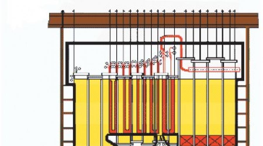
Brief description of the boiler unit "Direct-flow boiler type TPP-210"
Brief description of the boiler unit Once-through boiler type TPP-210 (p / p 950-235 GOST 3619-59 model TKZ TPP-210) with a steam capacity of 950 tons per hour for supercritical steam parameters was designed and manufactured by the Taganrog plant "Krasny Kotelshchik". The boiler unit is designed to operate in a unit with a K-300-240 condensing turbine with a capacity of 300 MW, manufactured by KhTGZ. The boiler is designed for burning anthracite sludge with liquid ash removal and natural gas from the Shebelinsky deposit. The boiler unit is made of two-case with a U-shaped layout of each case and regenerative air heaters removed from under the boiler, located outside the boiler house building. Boiler shells of the same design with a capacity of 475 t/h of steam each. The hulls can work independently of each other. General data on the boiler: Productivity 475 t/h Superheated steam temperature: primary 565 °C Secondary 565 °C Secondary steam consumption 400 t/h Primary steam pressure behind the boiler 255 kg/cm² Secondary steam pressure at the boiler inlet 39.5 kg/ cm² Secondary steam pressure at the boiler outlet 37 kg/cm² Secondary steam temperature at the inlet 307 °C Feed water temperature 260 °C Hot air temperature 364 °C Total weight of the boiler metal 3438 t Boiler width along the column axes 12 m Boiler depth along the column axes 19 m Height of the boiler 47 m Water volume of the boiler unit in the cold state 243 m³ Dimensions of the furnace in plan (along the axes of the pipes): primary and secondary steam at the outlet is reduced to 545 °C) The boiler is served by two axial smoke exhausters, two blowers with two-speed motors and two hot blast fans. Scheme of dust preparation with a bunker and transportation of dust to the burners by hot air. The boiler is equipped with three drum ball mills ShBM-50 with a capacity of 50 tons of dust per hour. Heating surfaces: Furnace screens 1317 m² Including: NRCh 737 m² THR 747 m² Reversing chamber screens and ceiling 1674 m² Superheater SVD: including: Steam heat exchanger 800 m² Intermediate convective package 1994 m² Air heater 78730 m² Outlet convection package 1205 m² Convective economizer 1994 m²
In each boiler body there are two streams (in the description of the boiler and in the instructions, the stream is called a thread). Since the hull design is similar, the scheme and design of one hull will be described in the future. Feed water with a temperature of 260 °C passes through the power unit and enters the inlet chambers of the Sh325*50 water economizer, which are also the extreme support beams of the package. After passing through the coils of the water economizer, water with a temperature of 302 ° C enters the outlet chambers Ш235*50, which are the middle support beams of this surface. After the water economizer, water is directed by bypass pipes Ш159*16 to the middle support beams of this surface through pipes Ш133*15 to the lower part (НРЧ). NRC screens consist of separate panels, and the hearth heating surfaces make up one-piece multi-pass tapes with the front and rear. Water supply to the panels is carried out through the lower chamber, and drainage from the upper one. This arrangement of the inlet and outlet chambers improves the hydraulic performance of the panel. The flow diagram of the medium through the NRC screens is as follows: First, the medium enters the rear screen panels and the rear panels of the side screen, then it is directed to the front screen and the front panels of the side screens by bypass pipes Ш 135*15. Washers Ш30 mm are installed on bypass pipes to improve hydrodynamics. After LFC, the medium with a temperature of 393 °C is sent by pipes Ш133*15 to the vertical collector Ш273*45, and from there it enters the side and front screens of the upper radiation part (RTC) via bypass pipes Ш133*15. The relative position of the inlet and outlet chambers of the TRC panels is similar to that of the RRC panels. Having passed the multi-pass panels of the front and side screens of the TCG, the steam is directed by bypass pipes Ш133*15 to the vertical mixing manifold Ш325*45, and from there it enters the N-shaped panels of the rear screen of the TRC through pipes Ш159*16.
Having passed the multi-pass panels of the front and side screens of the TRC, the steam is directed by bypass pipes Ш133*15 to the vertical mixing manifold Ш325*45, and after heating up to 440 °C in the radiant surfaces of the furnace, steam is directed to the panels of shielding side and rear walls of the rotary cameras. Having passed the screens of the reversing chamber, the steam enters through tubes into 1 injection desuperheater Ш279*36. In 1 injection desuperheater, flows are transferred across the width of the flue. After the desuperheater, steam is supplied to the ceiling superheater by pipes Ш159*16. In the ceiling superheater, steam moves from the rear wall of the flue to the front of the boiler and enters the outlet chambers of the ceiling Ш273*45 with a temperature of 463 °C. On the steam pipelines Ш273*39, which are a continuation of the outlet chambers of the ceiling superheater, valves (VZ) DU-225 built into the tract are installed. After the ceiling superheater, flows are transferred across the width of the gas duct, and the steam is directed through pipes Ш159*18 to the inlet screens of the first stage of the screen superheater, located in the middle part of the gas duct. Having passed the inlet screens, steam with a temperature of 502 °C enters the second injection desuperheater Ш325*50, after which it is directed to the outlet screens of the first stage, located along the edges of the flue. The steam receiving chamber of the inlet screens and the steam line of the second desuperheater carry out the transfer of flows along the width of the flue. Before the second injection, there is a steam pipeline Ш194*30 for removing part of the HPS steam to the gas-steam heat exchanger, and after the injection, there is a steam pipeline for returning this steam. The second injection desuperheater has a retaining washer. Behind the outlet screens of the first stage, there is a third injection desuperheater Ш325*50, the steam pipeline of which transfers flows along the width of the gas duct. The steam is then directed to the middle parts of the flue and, having passed them, is transferred by the steam pipeline Ш325*60 with a temperature of 514 °C along the width of the gas flue to the outlet screens of the second stage, located along the edges of the gas flue. After the outlet screens of the second stage, steam with a temperature of 523 °C enters the fourth injection desuperheater Ш325*60. Both inlet and outlet screens of both stages of the screen superheater have a co-current scheme of mutual movement of the steam and gases. After the desuperheater, steam with a temperature of 537 °C through the steam pipeline Ш237 * 50 enters the convective package, which is made according to the co-current scheme, passes through it with a temperature of 545 °C and is fed to the turbine. Starting from the inlet chambers of the water economizer, all bypass pipes and chambers of the SVD tract are made of 12Kh1MF steel. After the HPC of the turbine, steam with a pressure of 39.5 atm. The temperature of 307 °C is sent to the intermediate superheater in two streams. One “cold” line of low-pressure steam approaches the body; they split in two before the reheater. In the reheater of each housing there are two low-pressure steam flows with independent temperature control along the threads. Boiler design The walls of the combustion chamber are completely shielded by pipes of radiant heating surfaces. The combustion chamber of each body is divided by pinches formed by the protrusions of the front and rear screens into the combustion chamber (pre-furnace) and the afterburner. Screens in the pre-furnace area up to el. 15.00 fully studded and covered with chromite mass. Insulation of the combustion chamber and pinch in the furnace reduces the heat transfer of radiation from the core of the torch, which increases the temperature level in the pre-furnace and, consequently, improves the conditions for ignition and combustion of the fuel, and also contributes to a better formation of liquid slag. The combustion process of AS occurs mainly in the pre-furnace, however, combustion continues in the afterburner, where mechanical underburning decreases from 7.5-10% to 2.5%. In the same place, the temperature of the gases decreases to 1210 °C, which ensures the operation of the heating surfaces, the SVD superheater without slagging. The thermal stress of the entire furnace volume is Vт=142*103 kcal m 3 /hour, and the pre-furnace Vтп=491*103 kcal mі/hour.
The furnace of each of the two buildings is equipped with 12 dust-gas turbulent burners arranged in two tiers (three burners in each tier of the front and rear walls of the furnace). The gas supply to the burners is peripheral, the performance of the burner on dust is 0.5 t/h. Each turbulent burner has a built-in mechanical atomization oil nozzle with cooling and an organized air supply. To remove liquid slag, the pre-furnace has two cooled tapholes; the pre-furnace is made with a slope of 80 to the tapholes and is closed with fireclay bricks. Each furnace is equipped with two (according to the number of notches) mechanized slag removal units. Liquid slag is granulated in water baths and removed into slag-washing channels. The drying agent is discharged through rectangular burners, which are located on the side walls of the pre-furnace in two tiers: there are 4 burners in the lower tier, and 2 in the upper tier. There are manholes in the furnace for repair work. The firebox is shielded in the lower part up to 23.00 m by pipes of the lower radiation part (LRC), and in the upper part - by pipes of the upper radiation part (RTC) from the ceiling. The pipes of the rear and front screens of the NRCH have bends, which form the furnace pinch. The rear screen of the TRC in the upper part has a protrusion, which improves the aerodynamics of the gas flow at the outlet of the furnace and partially protects the screen surfaces from direct radiation from the furnace. The front and rear screens of the NRCH are structurally identical, each screen consists of six identical tapes, with pipes connected in parallel Sh42 * 6 material 12X1MF. The tape pipes are first screened under and the lower part of the pre-furnace, and then they pass to the vertical panel of the NRCH, where they make five lifting and lowering passages and exit into the upper chamber. The NRCH pipes are wired for the loopholes of burners, manholes, peepers. The side screens of the NRC consist of four panels, which are made as follows.
Leaving the lower chamber, the tape, consisting of 17 parallel-connected coils Ш42*5, material 12Х1МФ, first shields the lower part of the side wall, then moves to the vertical part, where it also makes five lifting and lowering moves, and then exits into the upper chamber. The front and rear screens of the NFC have two tiers of fixed mounts at the level of 22.00 and 14.5 m. Compensation from temperature expansion occurs due to the bending of the pipes at the pinch. The side screens are suspended by fixed mounts at 21.9 m and can be freely lowered. To prevent the exit of individual pipes into the furnace, the screens have five belts of movable fasteners. The front and rear screens of the TCG also consist of multi-pass panels with lifting and lowering steam movements. Steam is supplied to the lower chamber of the panels, removed from the upper ones. The middle panels of the front screen and all panels of the side screens consist of eight, and the extreme panels of the front screen of nine pipes connected in parallel, forming a tape. N - shaped panel of the rear screen of the TCG consists of twenty pipes connected in parallel. All heating surfaces of the VRC are made of pipes Ш42*5, material 12Х1МФ. The front and side screens of the TCG are fixedly suspended at the level of 39.975 m and expand freely downwards. The rear TCG screen has two fixed mounts at 8.2 and 32.6. Compensation for thermal expansion of the pipes occurs due to the bending of the pipes in the upper part of the rear screen of the TCG. The front and side screens have seven rows of movable mounts, the rear - three. All NRC and TRC screens have a pitch between pipes of 45 mm. The ceiling of the furnace and the top of the horizontal flue are shielded by pipes of the ceiling superheater. In total, there are 304 pipes connected in parallel (154 per thread) Ш32*4, material 12Х1МФ. Along the length of the pipes of the ceiling superheater there are 8 rows of fasteners, which are attached to the frame with rods.
Screen superheaters At the outlet of the furnace there is a screen superheater, which consists of two rows of screens. In a row of 16 screens with a pitch of 630 mm, suspended vertically. In the course of the steam, the screens of each stage are divided into inlet and outlet, which are located closer to the side walls of the gas duct. Structurally, the inlet and outlet screens of the first stage are identical (except for the location of fittings and bypass pipes on the chambers). The screen of the first stage of the boiler 20 consists of 42 coils Ш32*6, the pipe material is mainly 12Х1МФ, but for 11 extreme coils the outlet section is made by pipes Ш32*6, material 1Х18Н12Т. On the boiler, 19 screens of the first stage consist of 37 coils, material 1X18H12T. To give rigidity to the structure, the screen is connected by its 5 coils, which have fastening strips made of X20H14S2 steel. Screens of the second stage consist of 45 coils Ш32*6. The material of the entrance screens is 12Kh1MF, and the rest of the coils are made of steel 1Kh18N12T. The screen is connected by its six coils. The inlet and outlet chambers, except for the chambers of the second stage outlet screens, are joined into single manifolds separated by a partition. The chambers on rods are suspended from the frame beams. The walls of the turning chamber are shielded by four blocks. The blocks are made in the form of two-loop tapes. In each block there are 38 parallel-connected coils Ш32*6 material 12Х1МФ, which are located horizontally. Blocks have stiffening belts. The suspension of the blocks is carried out by means of three rows (per block) of fasteners. The following heating surfaces are located in the downcomer gas duct: a convective SVD stack, an LP superheater with a gas-steam heat exchanger, and a water economizer. For all convective surfaces, a staggered arrangement of coils is adopted. All surfaces are made of coils parallel to the front of the boiler.
Convective superheater SVD
The package of the SVD convective superheater of each line consists of 129 coils Ш32*6, material 1Х18Н12Т, which are based on racks made of Х23Н13 material, and those on support beams cooled by feed water. There are three rows of spacer strips made of 1X18H12T steel to withstand steps and make the structure more rigid; the package has a height of 557 mm. Low-pressure superheater The LP superheater is located behind the convective package of the SVD. The packages of each flow are located in the corresponding halves of the downcomer, the transfer of flows across the width of the flue is not carried out. The LP superheater consists of an output package, an intermediate package and a control stage. The output part of the LP superheater consists of 108 suspended coils Sh42*3.5, the material of combined steel: Kh2MFSR and 12Kh1MF. The coils are assembled in packages with racks, X17H2 material, which are suspended from the support manifolds of the high-pressure package. Package height 880 mm. The intermediate package also consists of 108 double coils Ш42*3.5 double coils Ш42*3.5 material 12Х1МФ. Package height 1560 mm. The coils are based on racks, material Kh17N2, and those on the inlet chambers of the intermediate package Sh325 * 50, material 12Kh1MF. Thus, the inlet chambers of the industrial package are also support beams for this heating surface. The chambers, in addition to insulation, have additional air cooling required during start-up modes and when the turbine is turned off. Behind the industrial package along the gas flow, on both bodies of the TPP-210 boilers, instead of the GPP TO, a control stage is installed, which is the first stage of the reheater along the steam flow, is made of pearlite steel and, according to the conditions of reliable operation of the pipes with significant devaporization, is located in the zone where the temperature of the gases is at inlet must not exceed 600°C. Its work is completely based on changing the heat absorption of the secondary steam by changing its distribution through the bypass steam pipelines. According to calculations, at the rated load of the unit, 20% of the total steam flow passes through the control stage. When the load of the unit is reduced to 70%, the steam consumption is 88%. The increase in the efficiency of the power unit is achieved by expanding the range of loads at which the design temperature of the secondary superheat is ensured with optimal excess air. The control surface is installed in the dimensions of the dismantled GPP TO, the input manifolds are lowered 300 mm lower. The control surface consists of left and right parts with a total heating surface of 2020 m² per body. Both parts are assembled from packages of twin coils and have 4 loops along the gas flow with a countercurrent steam flow pattern. The coils are made of pipes Sh32*4, steel 12Kh1MF and are arranged in a checkerboard pattern with steps of 110 and 30 mm. The coils are assembled into packages using stamped racks made of steel 12X13. 5 racks are installed along the length of each package. Two of them are installed on water-cooled collectors located in the gas duct, which are lowered 290 mm during the repair. The steam from the HPC enters the inlet chambers of the control surface Sh425*20 steel 20. Having passed the coils, the steam enters the outlet chambers with a diameter of 426*20 steel 12Kh1MF, where it mixes with the steam coming from the bypass steam pipeline. The old RKT valves were cut out along the lines "B" and "C" from the old RKT, the internal parts were taken out and the RKT bodies were scalded and used as tees. On the bypass line between the inlet and outlet manifolds, new RKT gate valves are installed. When the valve is opened to 100%, steam in the amount of 80% goes past the control surface and the p / p decreases. When the valve is closed, the steam passes through the control surface and the reheat temperature rises. KDU and control keys of the new RKT remained the same. The water economizer coils on both hulls have been replaced (100%). Retaining washers were dismantled on the manifolds of the second injection and the outlets to the GPP TO were turned off. The convective economizer is the last heating surface in the gas flow, located in the downcomer. It consists of pipes Ш32*6, material st20. The outlet and inlet chambers of the economizer are also supporting beams - the weight of this heating surface is transferred to them through the racks. The frame of the boiler is made in the form of identical frames of both buildings, interconnected by inter-hull connections and transitional scaffolds. The weight of the heating surface, lining and insulation is transferred with the help of horizontal beams and trusses to three rows of vertical columns, one row along the front of the boiler, the other between the furnace and the downcomers and the third one at the back of the boiler. To stiffen the frame, there are a number of inclined beams. Furnace lining, boiler gas ducts are made in the form of separate shields. The furnace and flues are sheathed with sheets 3 mm thick, which ensures a high density of the furnace and flues.
Changing am from 1.12 to 1.26 leads to a decrease from 2.5 to 1.5% for the second fuel group. Therefore, to increase the reliability of the combustion chamber, it is necessary to maintain an excess of air at the outlet of the furnace more than 1.2.
In the table. 1-3 in the range of changes in the thermal stress of the furnace volume and fineness of grinding /? 90 (Fig. 6-9, c, d), their influence on the value was not found. It was also not possible to reveal the influence of the ratio of the velocities of the secondary air and the dust-air mixture in the studied range of their change on the efficiency of the furnace operation. However, with a decrease in air flow through the outer channel (at reduced loads) and a corresponding increase in air through the inner channel (at a constant flow through the burner), the slag output improves. The jets of slag become thinner and their number increases.
With uniform distribution of dust and air. there is no chemical underburning at the furnace outlet for burners and at at > 1.15.
The gross efficiency of the steam generator when burning coal (1/g "14%) and at rated load reaches 90.6%.
Similar results were obtained in the work, confirming that the TPP-210A steam generator operates economically and reliably also when burning AS (1/g = 3.5%; 0pc = 22.2 MJ/kg;
With excess air in the furnace at = 1.26h-1.28, grinding fineness /?9o = ----6-^8%, in the load range D< = 0,7-^ 1,0£)н величина потери тепла с механическим недожогом достигает 3%. Максимальный к. п. д. брутто парогенератора при номинальной нагрузке составляет 89,5%.
The paper presents data stating that when anthracite is burned in the combustion chamber of the TPP-210A steam generator, the value of mechanical underburning<74 в условиях эксплуатации примерно в 1,5 ниже, чем при работе котлов ТПП-110 и ТПП-210 с двухъярусным расположением вихревых горелок мощностью 35 МВт.
The conducted studies, as well as long-term pilot operation of the TPP-210A steam generator, showed that in the range of load changes from 0.65 to the nominal value, the combustion chamber operates economically and stably, without dust separation and without violations of the liquid slag removal regime.
The duration of the campaign (before the overhaul) of the steam generator with dust-gas burners without their repair was 14545 hours. At the same time, the condition of the burners was satisfactory; burning of the brick embrasures, warping of gas pipes and nozzles is insignificant.
When inspecting the combustion chamber during shutdowns, no accumulation of slag on the hearth and slagging of the walls of the afterburning chamber were observed. The entire studded belt was covered with a smooth, shiny film of slag. The drift of convective heating surfaces was also not observed.
Turning off any one burner or two medium burners does not reduce the stability of ignition, does not affect the mode of liquid ash removal and does not lead to a violation of the temperature regime of the LRC and TRC.
Litter AS ENERGY RESOURCE. Let's make a reservation right away that the use of native (without litter) manure to meet energy needs is much more expensive in comparison with bedding manure in terms of both capital and operational ...
COMPLEX METHOD OF UTILIZATION OF CHICKEN MANURE WITH OBTAINING ORGANOMINERAL FERTILIZERS AND COMBUSTIBLE GAS, THERMAL AND ELECTRIC ENERGY Manure is a strong pollutant of soil, water and air basins. At the same time, litter…