At rated steam parameters, adjustable extraction and power. Turbines with two heating steam extractions
Comparative analysis three selection schemes that are used in home brewing and distillation columns. The characteristics, advantages and disadvantages, as well as applicability in various options distillation. Each method has its own type of equipment.
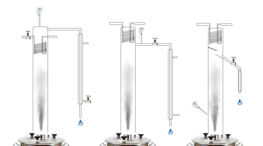
To work successfully with a column, you need to adjust the reflux ratio. There are three methods for this:
- CM (cool managment) – control of the flow of water supplied to cool the reflux condenser;
- LM (liquid managment) – control of the amount of reflux withdrawn (liquid selection);
- VM (vapor managment) – control of the amount of vapor taken (steam selection).
 Methods for controlling a distillation column
 Before we start talking about types of selection, let's define the terms.
Distillation– the process of evaporation of a liquid followed by condensation.
If the raw material was initially evaporated from the distillation cube, then condensed in a refrigerator (condenser), then no matter what happens in the middle of this process (the passage of steam through a steamer, bubbler or reflux condenser), ultimately a distillate will still be obtained.
Rectification- This is one of the distillation methods, which is distinguished by two technological methods:
Forced, strictly controlled return of reflux using special devices - reflux condensers or condensers.
Heat and mass transfer is organized between the phlegm and the steam rising towards it. To increase the efficiency of heat and mass transfer, use a nozzle or dish columns, where re-evaporation of phlegm occurs. In the first case, the process is film in nature, in the second - bubbling.
The purpose of rectification is to obtain alcohol of a given strength and purify it from impurities. To do this, the reflux ratio must always be higher than the minimum (more details on the graph).

The quality of the product depends on the reflux ratio, but the higher it is, the lower the productivity of the column.
Rectification does not allow one to isolate any mixture from a group, but only more or less completely removes all impurities grouped by similar volatility. Therefore, if you use rectification equipment to obtain, for example, fruit distillates, there is a risk of grouping the head fraction into difficult-to-separate azeotropes - removing useful esters responsible for the aroma along with unnecessary impurities.
If you try to remove noble distillate using rectification equipment, you need to ensure that the reflux ratio does not exceed 1.5-2 during the entire selection. Otherwise, the balance of impurities will be upset.
Types of selection units in a column
Liquid managment
LM – adjustment of the amount of liquid withdrawal. The most convenient and easy-to-use scheme is in which all vapors are condensed, then one part of the condensate is returned to the column, the other goes to the selection.
Characteristics. The reflux ratio is adjusted using one needle tap for alcohol selection. If the tap is fully open, the reflux ratio is zero, and the output is a regular distillate. When the tap is closed, the reflux ratio is infinitely large - the column works for itself. Adjusting the liquid tap allows you to change the reflux ratio from 0 to 100% at any time. The heating and cooling power is set at the optimal level, ensuring maximum separation capacity of the column and minimal reflux cooling.
Column with liquid withdrawalAs a rule, the reflux ratio is set slightly higher than the minimum, which, when selecting a “body,” allows one to go without adjustments for a relatively long time, but closer to the end of the selection, one still has to actively regulate the process. Moreover, the less alcohol remains in the cube, the more often it is necessary to increase the reflux ratio.
Advantages:
- suitable for producing both aromatic and pure alcohols;
- easily and relatively cheaply automated up to the automated control system ( automated system control) of the production process with safety units;
Flaws:
- If you fix the selection rate at the same level, then as rectification proceeds, the reflux ratio will fall. This contradicts the technological need to gradually increase the speed towards the end of the selection, which is the main disadvantage;
- it is necessary to break the jet (connection with the atmosphere) after the control tap or valve, otherwise there may be failures in adjusting the sampling rate due to the vacuum in the sampling line, which is created by the flowing flows of alcohol.
Vapor managment
VM – regulation by dividing steam flows to the dephlegmator. The column is controlled by changing the amount of extracted steam using a gate valve or a conventional ball valve.
Characteristics. Area ratio cross section column and steam outlet pipe determines the minimum reflux ratio, which can be increased by adjusting the position of the valve.
 Column with steam extraction
 During distillation, the amount of reflux returned is adjusted from 80 to 100%. The minimum possible reflux ratio is 4.
Advantages:
- sensitivity to the position of the tap is very low, which allows precise adjustments;
- the reflux ratio does not depend on changes in temperature or flow rate of cooling water in the reflux condenser;
- There is no increased sensitivity to cooling water pressure stability.
Flaws:
- the control system is inertial, from changing the position of the valve to changing the withdrawal speed can take up to 10-15 seconds;
- not suitable for producing aromatic alcohols from natural raw materials. Design changes are required to allow the amount of reflux returned to be adjusted from 50 to 100%;
- the steam extraction column is sensitive to plugs in the product withdrawal line. If a column of product forms in the silicone hose, flowing down, it will create a vacuum and, like a pump, will pull steam towards itself, violating the set reflux ratio. As a result, the selection rate will increase sharply and uncontrollably; without operator intervention, the system will not return to its previous level. Uncontrolled selection can be stopped by establishing a connection with the atmosphere (creating a break in the jet). For example, insert a needle from a syringe into the upper part of the sampling tube;
- automation is complex and expensive. It is often performed in the form of a signaling device for reaching certain temperatures, but without actuators. Automatic security is also desirable.
Cooling management (cool managment)
CM – adjustment of the amount of water supplied to the reflux condenser. Allows you to control the amount of steam passing through the reflux condenser to the product selection refrigerator.
Characteristics. The reflux ratio is adjustable from 0 to 100%, but the system is very sensitive to the amount of water supplied and requires a precision needle valve. To regulate the selection speed, you have to turn the tap literally a fraction of a millimeter. The heating power must be constant throughout the entire process and ensure maximum separation capacity of the column. With an increase in the amount of supplied water, the amount of returned reflux also increases, and accordingly, the reflux ratio increases.
 Column with adjustable water supply to the reflux condenser
 During rectification at constant cooling and heating power, a gradual decrease in the selection occurs, but the reflux ratio remains unchanged.
Advantage:
- can be successfully used to produce aromatic alcohols from natural raw materials.
Flaws:
- The slightest fluctuations in pressure lead to changes in the withdrawal rate and reflux ratio. If measures are not taken to stabilize the cooling water pressure in the apartment, even a toilet flushed by neighbors will affect the selection process;
- an increase in the temperature of water in the reflux condenser while its quantity remains unchanged reduces the reflux ratio, therefore, to maintain a stable reflux ratio, control over the flow rate and temperature of the water supplied to the reflux condenser is necessary;
- communication with the atmosphere in the product selection line is required, otherwise if the heating is accidentally turned off and the tube is immersed in the selection, the entire product will again end up in the cube;
- the system is expensive and difficult to automate. Usually for such distillation columns they install simple thermal alarms and automatic safety systems.
Practice of installing different selection units on columns
Liquid withdrawal (LM) columns
In home columns, liquid selection is most widely used. The reason is simple - the process of rectification of 40 liters of moonshine takes 18-20 hours. You can reduce the bulk by half, but then the share of recycled (technical) alcohol, which will have to be processed during each rectification, increases sharply.
If we talk about the performance of the system as the amount of commercial alcohol obtained per total time rectification (including heating), then when the bulk volume is reduced by 2 times, the efficiency decreases by approximately 1.5 times.
Another way to minimize the volume of industrial alcohol produced while maximizing productivity is to automate the process, which allows distillation to be carried out according to a predetermined algorithm without operator participation. The automation system must have not only an executive circuit, but also a safety unit that will instantly turn off the equipment if there is a threat of an accident.
A distillation column with liquid extraction is automated more easily and cheaper than other systems, and in terms of the quality of the resulting alcohol it is in no way inferior to other types of equipment.
Columns with steam extraction
Steam selection systems are common abroad, where alcohol and its derivatives are inferior in popularity to distillates (cognac, whiskey, etc.), but the high strength of the drink is valued. Foreign craftsmen are constructing distillation columns with steam extraction, which have a minimum reflux ratio - only 1, and not 4 as in Russia. With this scheme, at least 50% of the reflux goes back into the column.
In distillation mode, steam extraction practically does not require automation. The reflux ratio set at the start of the “body” selection remains unchanged until the end; only the operator can change it, but even when receiving alcohol, adjustment is needed literally a couple of times.
The rate of selection towards the end of the distillation sharply decreases until it stops. If you want to hunt for enanthic esters (they largely create the organoleptic properties of fruit distillates), change the jars and increase the heating power, followed by fractional selection and sorting.
If enanthic esters are not required, do the same, but additionally use pauses for the column to work on itself so that the alcohol residues are more concentrated and with fewer impurities.
Automation in columns with steam extraction is needed only at the level of the safety unit. In addition, obtaining a distillate does not involve grouping impurities into fractions and completely removing them, but a balanced reduction in the concentrations of substances to an acceptable level with the obligatory preservation of flavor and aromatic components. This is a matter for the master distiller who controls the process; adjustment by instruments is inappropriate here. Bulk is limited by the volume that can be distilled under human direction in the time available.
Columns with adjustable water supply to the reflux condenser
Despite all the shortcomings, this type of equipment is often used in Russia during construction mash columns. The reason is the possibility of obtaining distillates from any raw material, and if necessary, without changing the design (an additional drawer does not count), you can collect the distillate high degree cleaning - almost like alcohol.
Columns with control of the water supply to the dephlegmator are expensive to automate and are sensitive to the pressure and temperature of the cooling water, which makes them poorly suitable for producing pure rectified alcohol, but with small bulk quantities of up to 20 liters and the constant attention of the operator, such columns are capable of much.
In addition, the cool managment scheme is the best for selecting “goals”. All other things being equal, it is impossible to obtain more concentrated “heads” using vapor and liquid extraction systems. True, this is only if you manage to stabilize the temperature and pressure of water in the reflux condenser.
IN last years Attempts are being made to create hybrid distillation columns, in which the “heads” are selected by steam using the SM method, and the “body” by liquid (LM). This improves the already high quality of alcohol in the LM columns. There are no boundaries for perfection.
When constructing mash columns focused on aromatic distillates, VM equipment has an advantage over SM due to ease of control, as well as insensitivity to temperature and water flow in the dephlegmator - more predictability in “combing out” impurities. For sugar raw materials mash columns according to the SM scheme, it is more promising due to better removal of the head fraction. But managing them creates many problems.
Modern heating turbines with a power of 50 MW and above have two heating controlled steam extraction for stepwise heating of network water, carried out in several sequentially located heaters. The pressure of the extracted steam is determined by the temperature of the water leaving each heating stage. To heat the network water, 70-80% of the steam flow to the turbine is used, and the heating temperature is 40-50 °C.
Schematic diagram turbine installations with two heating extractions (upper 4 and lower 5) is shown in Fig. 20.2, a. Fresh steam in quantity G O and with parameters p 0, t 0 is supplied to the turbine through a stop valve 8 and regulating 7 valves. In the ChVD 1 steam expands to pressure in the lower heating outlet 5 and then through the regulator 6 sent to CHND 2. The rest of the equipment of a turbine installation with two heating steam extractions is similar to a turbine with two controlled steam extractions (Fig. 20.1).
Rice. 20.2. Schematic diagram (A) and steam expansion process (b) V h,S-diagram of turbine stop with two-stage steam extraction.
To the top selection 4 steam with flow G 1 withdrawn at pressure R 1 and with enthalpy h 1 (Fig. 20.2, b), and to the bottom - steam with flow G 2 with parameters R 2 And h 2 . Since there is only one regulating body in the turbine, the adjustable pressure at the same time can be maintained only in one of the two heating steam extractions: in the upper one - when both extractions are turned on, in the lower one - when the lower extraction is switched on.
The installation for heating network water consists of two heaters (boilers) 9 And 10 surface type. The required temperature of the network water supplied to the heat consumer is determined by the pressure of the upper extraction steam. The distribution of the heat load between the upper and lower selections is determined by the temperatures of the network water before and after the network heaters, the flow rate of the network water and the electrical load.
Turbine internal power N i , kW, with two heating outlets the pair is determined from the expression (without taking into account regenerative selections)
N i = N uh / η m η eg = N i "+N i " " + N i """ =
= G o N 0 "η 0i " + (G O –G 1 )N 0 ""η 0i "" + (G O –G 1 –G 2 )N 0 """η 0i """ (20.3)
, kW, isQ t = W with c in (t 2s -t 1s) = G 1 (h 1 -h 1 " ) + G 2 (h 2 -h 2 " ), (20.4)
Where G O ,G p ,G t - steam consumption to the turbine, to the upper and lower heating outlets, kg/s; N 0 " , N 0 "" , N 0 """- located turbine stages up to the upper extraction, between the extractions and the low pressure , kJ/kg; W with - consumption of network water, kg/s; c in=4.19 kJ/(kg K) - heat capacity of water; t 2s,t 1s- water temperature at the inlet and outlet of the heaters, degrees; h 1, h 2 - enthalpy of steam in the upper and lower heating extractions, kJ/kg; h 1 " , h 2 " - enthalpy of heating steam condensate in heaters 9 And 10, kJ/kg.
Turbines with two-stage steam extraction can have a variety of heating operating modes depending on the ratio of thermal and electrical loads. At operating modes thermal chart at a given thermal load Q t regulatory body 6 closed before CHND. The turbine power is determined by the thermal load, and the steam flow through the LLP is limited to the value Gk.min, determined by conditions reliable operation turbines. When the turbine operates according to the electrical schedule independent changes in thermal and electrical loads are possible. Regulatory Authority 6 partially or completely open, which allows flow through the turbine at a constant heat load additional expense fresh steam entering through the LPC into the condenser 3 (Fig. 20.2). This flow rate provides additional power compared to operating mode according to the thermal schedule with the same thermal load. Thus, the steam flow through the low pressure pump depends on the given electrical load.
20.3. APPLICATION OF BUILT-IN BEAMS IN CONDENSERS OF HEATING TURBINES
In turbines with controlled steam extraction, during operating modes with thermal load, zero steam passage into the condenser is not allowed. Minimum pass, which serves to cool the stages of the low-pressure pump, is determined turbine design(dimensions of the blades of the low-pressure disk, density of the regulatory bodies of the low-pressure disk, etc.) and its mode of operation(vacuum, pressure in the sampling chamber).
The heat of the steam entering the condenser is transferred to the circulating water and is not used in the power plant cycle. The heat of the steam entering the heat exchangers located on the recirculation line is also transferred to the circulating water: stuffing box heater and ejector coolers. To utilize this heat, commensurate with the heat of maximum steam passage into the condenser, part of the condenser surface is allocated to a special heating beam. The bundle tubes provide a supply of both circulating water and heating network water. The built-in beam surface is approximately 15% total area surface of the capacitor.
The design of a condenser with a built-in beam, having independent water chambers and a common vapor space with the main surface, is standard solution for district heating turbines with a capacity of 50 MW and above.
Schematic diagram of a turbine installation with a built-in heating bundle in the condenser shown in Fig. 20.3, a. To the main condenser tube bundle 8 only supply of circulating water is provided, and to the built-in bundle 11 - circulating water and water from heating networks (return network or make-up). The rest of the turbine installation equipment has the same purpose and image as in a turbine installation with two-stage steam extraction (Fig. 20.2).
In condensing power generation mode Only circulating water flows into the main and built-in bundles. When working according to a thermal schedule the supply of circulating water to the main and built-in bundles is turned off, and the built-in bundle is cooled by network or make-up water. In this case, the regulatory authority 6 CHND (Fig. 20.3 ,a) is closed, and the turbine operates in a mode similar to the operation mode of a turbine with back pressure.

Rice. 20.3. Circuit diagram(s) and steam expansion process (b) V h,S-diagram of a turbine installation with two-stage steam extraction and a built-in heating unit.
At the same time, the possibility of independently setting thermal and electrical loads is excluded, since electric power turbine in this operating mode is determined by the value and parameters of the thermal load.
Switching the turbine to operate using the built-in beam causes a redistribution of pressures and heat drops across the turbine stages. In Fig. 20.3b shows the thermal process of steam expansion in a turbine h,S-diagram when operating in condensing mode(dashed lines) and with switched on heating bundle(solid lines). For high pressure turbines operating mode with the built-in beam on associated with an increase in pressure in regulated extractions ( R 1 >R 1 "; R 2 >R 2 "), which leads to a decrease in power generated from steam flows into extractions. In the low pressure turbine, due to deterioration of the vacuum in the condenser, the available heat drop sharply decreases ( H 02 " > H 02 ), and its stages operate at a high speed ratio i/s f and lower efficiency. In some cases, energy losses in the low-pressure unit exceed its available heat drop and the low-pressure stages operate with negative efficiency and consume power (line 1-2 in Fig. 20.3, b). Under such conditions, due to an increase in the temperature of the steam passing through the low-pressure pump, the temperature regime turbine exhaust pipe.
SRS. MODE DIAGRAMS
In general mode diagram expresses in graphical form the relationship between the electrical power of the turbine N i, steam consumption G O, thermal load of the consumer Q p (Q t), steam pressure supplied to the consumer R p (p t), fresh steam parameters р 0 , t 0, cooling water flow W With etc., determining the operating mode of the turbine unit:
F(N e, G 0 , W s,Q p,Q t, R n, r t...) = 0. (1)
Equation (1) is represented graphically on a plane if the number of variables does not exceed three. Otherwise, an image of a regime diagram on a plane can only be obtained by replacing the actual relationship of variables with approximate dependencies, which introduces an error into the diagram, the larger the number. equation variables(1). Therefore, it is advisable to limit the number of independent parameters participating in the regime diagram. When limiting the number of variables in equation (1), it is taken into account that the influence of individual parameters on power is not the same. To ensure the ultimate high precision the regime diagram is performed in the form of several independent graphs. Main schedule, usually called mode diagram , expresses relationship between turbine power N e and steam consumption G 0 . Additional graphs, called correction curves to the regime diagram , determine the effect of changing each of the other parameters of equation (1) on the turbine power. IN The composition of the mode diagram includes also some auxiliary curves: dependence of the feed water temperature on the fresh steam flow rate, the possible minimum pressure in the controlled extraction on the steam and extraction flow rates, etc.
The basic diagram can be done with high accuracy, since the number of variables is limited. Correction curves are usually performed with some error. However, the error of the correction curve slightly increases the overall error of the mode diagram, since absolute value The corrections themselves usually amount to several percent of the total turbine power.
The presence of a mode diagram allows you to graphically establish the relationship between the parameters of equation (1) and highlight the area of possible operating modes of the turbine unit. The clarity of presentation, ease of use and sufficient accuracy have determined the widespread use of mode diagrams in the design and operation of thermal power plants.
SRS 19.1. Diagram of regimes of a turbine with back pressure type P. The mode diagram expresses fresh steam consumption dependence G 0 from electrical power N e and back pressure r p :
G 0 =f(N e, r p). (2)
which can be presented on a plane in accordance with available experimental or calculated data. Of the three parameters of equation (2), the final steam pressure has the least influence r p , and therefore the regime diagram of the turbine with back pressure is fulfilled (Fig. 19.1 SRS) in the form of a grid of curves G 0 =f(N e) , obtained as a result of the intersection of the three-dimensional surface described by equation (2) with planes r p = const.

Rice. 19.1 SRS. Diagram of turbine modes with back pressure.
SRS 19.2. Diagram of turbine modes with one adjustable steam extraction. In general, the regime diagram expresses electric power dependence N e from steam flow to the turbine G0, to the selection G p and steam pressure in the selection r p.
G 0 =f(N e, G p, r p). (3)
Selection pressure can be removed from this equation r p , replacing its influence with correction curves that can be performed with a relatively small error. Then dependence (3) can be plotted on a plane in the form of a series of curves G 0 =f(N e) at G p = const.
Let's consider example of constructing a turbine mode diagram with steam extraction an approximate method based on the use of a linearized dependence of steam flow per turbine G 0 from power N e and steam consumption in extraction G p:
G 0 = G co + y p G p = G k.x + r k N e + y p G p = G k.x + d n (1- x)N e + y p G p (4)
Where G co = G k.x + r k N e - steam flow to the turbine in condensing operating mode without extraction; G k.x - steam consumption when the turbine is idling without extraction; r to =(G 0 - G k.x )/N e - specific increase in steam consumption during condensation mode, kg/(kWh); y p = (h p -h k) / (h 0 -h k) - the ratio of the used heat drops of the low-pressure unit and the entire turbine (the coefficient of underproduction of power by the extraction steam); d n =G nom/N nom- specific steam consumption at rated load and condensation mode of operation, kg/(kW h); x=G x.x /G 0 - idle speed coefficient.
The basis of the mode diagram is the boundary lines constructed for the most characteristic turbine operating modes.
Condensation mode. Mathematically, the dependence of steam consumption on power is determined by expression (5) at G p =0:
G 0 = G co = G c.x + d n (1- x)N e (5)
Graphically (Fig. 19.2 SRS) the condensation regime line is constructed using two points: point TO, the ordinate of which corresponds to the maximum passage of steam into the condenser at rated electrical power N nom, and point O 1 , which determines the steam flow to the turbine G k.x at zero power ( idling). On the abscissa axis there is a line of condensation mode passing through the points TO And O 1 , cuts off a segment O O 2 , conditionally determining turbine power loss Δ N x.x to overcome idle resistance.
In reality, addiction G 0 =f(N e) in condensation mode it differs from straight line and has more complex look, determined by the steam distribution system, the nature of the change in the internal relative efficiency, the temperature of the steam exhausted in the CHP, etc.
Turbine operating mode with back pressure. The change in steam flow to the turbine is determined by expression (5) at G to =0 And G 0 =G p:
G 0 = G o.p = G p = G k.x + d n (1- x)N e + y p G 0,
G 0 = G k.x/(1- y p) + d n (1- x)N e /(1- y p) = G p.x + r p N e (6)
G co + y p G p = G k.x + r k N e + y p G p = G k.x + d n (1- x)N e + y p G p
Where G p.x =G k.x /(1- y p) - steam consumption at idle in mode with back pressure, kg/s; r p = r to (1- y p) - specific increase in steam consumption when operating a turbine with back pressure, kg/(kWh).
Since the underproduction ratio y p is always less than unity, the steam consumption at idle and the specific increase in steam consumption when the turbine operates with back pressure is higher than during condensation mode in (1 /(1- y p)) once: G p.x >G k.x , r p >r to.
This is explained by a significantly lower heat drop in the turbine before the extraction compared to the total heat drop to the condenser and a correspondingly larger specific consumption pair.

Rice. 19.2 SRS. Diagram of turbine modes with one adjustable steam extraction.
An approximate dependence of steam consumption on power in the case when all the steam after high-pressure injection enters the extraction, in the regime diagram (Fig. 19.2 SRS) is represented by a straight line passing through the point O 2, characterizing the loss of power at idle, and the point O 3 , wherein G p.x =G0. Dot B 0 , lying on the condensation regime line G to = 0, corresponds to the operating mode with maximum steam flow through the turbine.
In reality, when the turbine operates with back pressure, a small flow of steam is passed through the condenser G k.min, which is determined by the conditions for reliable operation of low pressure turbine elements (5-10% of steam flow per turbine). As a line of operating modes of a turbine with back pressure and minimal steam flow into the condenser, satisfying equation (5), we should consider the straight line K o V , parallel O 2 V 0 and located below it. Ordinate point K o characterizes the minimum passage of steam into the condenser G k.min.
Operating mode with constant steam extraction(G p = const). The characteristics of a turbine with constant steam extraction are constructed according to equation (4). From a comparison of expressions (4) and (5) it is easy to establish that the characteristics of the condensation mode and the operating mode with constant extraction differ from each other by a constant amount y p G p . Therefore, on the mode diagram, the lines depicting the mode G p = const, will be located parallel to the condensation mode line.
The left boundary of the turbine characteristics at G p = const serves as the line of operation of the turbine with back pressure, on which G p = G k.min(in the absence of unregulated steam extraction), and the right - line KV n constant rated turbine power N nom. The upper part of the mode diagram is limited by the segment BB n on the line of maximum steam passage through the turbine G 0max = const between the lines G k.min = const And N nom = const.
Nominal steam extraction G p nom corresponds to rated electrical power N nom and maximum steam flow per turbine G 0max (dot V n ). If the maximum steam flow to the turbine is achieved when operating with back pressure at an electrical power less than the rated one, then it is possible to extract more steam than the rated one, the so-called limiting extraction, determined at the point IN line intersections G k.min = const And G 0max = const.
In addition to the obligatory family of lines that determine the dependence of turbine power on steam flow at different meanings selections G p = const, the mode diagram has a grid of lines G to = const at constant steam flow to the condenser (CND). Lines G to = const are straight, parallel to the characteristics of the turbine operating mode with back pressure G k.min = const. Of this family of lines, the most significant line is G k.max = const, corresponding to the maximum passage of steam into the condenser. Usually from heating turbine with steam condensation, the full development of electrical power in a purely condensing mode is required. In this case, the bottom line of the diagram G p = 0 reaches the line N nom = const at the point TO at G To =G k.max. If the steam selection is stable and ensured a long period operation of the turbine unit, then the lower boundary of the right side of the diagram is the line G k.max = const, running parallel to the line G k.min = const above the point TO line intersections G p = 0 And N nom. In this case, the rated electrical power is achieved at a certain extraction value.
With the simultaneous maximum passage of steam through the high-pressure pump and low-pressure pump, the turbine can develop maximum power N Max. This power is determined by the abscissa of the point In t line intersections G 0max = const And G k.max = const. Maximum power turbines are regulated at up to 20% higher than nominal.
If we assume that the steam flow through the low pressure pump should not exceed the maximum, then from the diagram (Fig. 19.2 SRS) it is clear that in condensation mode ( G p = 0 ) turbine power (point K 1 ) will be less than the maximum. Such a limitation on the power of a turbine with controlled steam extraction when operating in condensing mode is unjustified. The rated power in condensing mode can be obtained by increasing the passage of steam through the low-pressure pump, which is ensured by increasing the steam pressure in front of the low-pressure pump. Modes with steam flow rates through the low-pressure pump exceeding it throughput with fully open regulatory bodies PND and nominal pressure pair in regulated selection, in the regime diagram are highlighted in the area “ high blood pressure in regulated selection”, which is shown in Fig. 19.2 SRS shaded.
The mode diagram allows you to determine the third from two given terms of expression (3). Determination of extracted steam flow G p N uh and steam consumption G 0 happens as follows. According to known N uh And G 0 find a point A , characterizing the given turbine operating mode. Through the point A draw a line of constant steam passage into the low-pressure pump. Ordinate point WITH intersection of this line and the condensation mode line G p = 0 determines the steam flow in the low-pressure pump G to . The consumption of the extracted steam is found as the difference G p =G 0-G to .
Fresh steam consumption G 0 with known turbine power N uh and consumption of extracted steam G p determined by the ordinate of the point of intersection of the lines
N e = const And G p = const.
Turbine power N uh at known flow rates of fresh and extracted steam G 0 And G p determined by the abscissa of the point of intersection of the lines G 0 = const And
G p = const.
SRS 20.1. Diagram of turbine modes with two adjustable steam extractions. N uh, steam flow per turbine G 0 , steam flows to the upper (production) and lower (heating) extractions G p And G T:
G 0 =f(N e, G p, G T). (1)
The influence of the remaining parameters of equation (1) is taken into account by the correction curves.
When constructing a diagram of the regimes of a turbine with two adjustable steam extractions, it is conditionally replaced by a fictitious turbine with one upper steam extraction. The cogeneration extraction is assumed to be zero, and the steam is sent to the low pressure turbine and produces additional power there
ΔN t = G t N i "" η m η eg = kG t (2)
Where N i "" - used heat drop of the low-pressure unit; k - proportionality coefficient.
Taking into account (2), expression (1) can be reduced to the form
N e = N e conv - ΔN t = f(G 0 , G P) - G t N i "" η m η eg (3)
Where N e conv =f(G 0 , G P)- power developed by a conventional turbine at zero cogeneration extraction.
The mode diagram corresponding to expression (3) can be made on a plane in two quadrants as follows (Fig. 6.9). In the upper quadrant the dependence is built G 0 =f(N e conv , G p) , which expresses a diagram of the modes of a conditional turbine when operating with zero steam flow into the heating outlet. Its construction is carried out in the same way as for a turbine with one steam extraction (Fig. 19.2 SRS). The lower boundary of this diagram is the production selection line G p = 0 . At the top, the diagram is limited by the lines of maximum steam flow per turbine G 0max = const and in production selection G p.max = const, as well as the line G chsd, characterizing the amount of steam included in the BSD .

Rice. 20.1 SRS. Diagram of turbine modes with two adjustable steam extractions.
In the lower quadrant, according to (3), a line is drawn OK , connecting the lower heating outlet G T with extra power ΔN T, and a grid of lines parallel to it is drawn. In addition, boundary lines are drawn here G p = const for district heating extraction. They depict the maximum possible production selection G p.max, which is determined from the general steam balance turbines, provided that the steam flow at the exit from the ChSD does not exceed the heating extraction by the amount required to cool the stages of the ChSD:
G t.max = G 0max -G p -G kmin .(4)
These boundary lines are constructed as follows: from randomly selected points 1 And 2 for the same value G p = const draw vertical lines down. Points 1" And 2" intersections of these lines with the values G t.max, calculated according to formula (4), are combined for one value G p = const straight line, which is the boundary of possible modes. Below it, turbine operation is unacceptable due to G T > G t.max .
Using this diagram (Fig. 20.1 SRS), it is possible to find the fourth for a turbine with two controlled steam extractions using three known values of equation (1). Let, for example, be given N uh, G p, G t. Need to find G 0 . First by N uh And G T find N f: from point A given power N uh carry out direct AB, parallel OK, until it intersects with the line constant flow G p = const. Line segment AC depicts the additional power generated by the low pressure pump due to the additional passage of steam in the amount G T. Fictitious turbine power N f determined at point C. Using the upper part of the mode diagram, according to N f determine the required steam flow to the turbine G 0 as the ordinate of a point D intersections N f = const And G p = const.
CPC 20.2. Diagram of turbine modes with two heating steam extractions. The diagram expresses the relationship between turbine power N uh, thermal load Q t, steam flow per turbine G 0 , network water temperature t s, going to the consumer:
F(N e , Q t, G 0, t c)=0. (5)
The regime diagram is constructed using the method of dividing the fresh steam flow into two flows: heating G t 0 and condensation G To 0 . Accordingly, the turbine power is conventionally assumed to be equal to the sum of the power of the heating plant N t e and condensation N k e streams. Taking this into account, dependence (5) can be represented in the following form:
G 0 = f 2 (N t e , t 2s) + f 3 (N to e) (6)
The mode diagram is built in three quadrants (Fig. 20.2 SRS).

Rice. 20.2 SRS Diagram of turbine modes with two heating steam extractions.
The first (upper left) shows the dependence of steam flow to the turbine on the thermal load when operating according to the thermal schedule G t 0 =f 1 (Q t,t 2s). The second (upper right) quadrant shows the dependence of the steam flow to the turbine on its power at various values t 2s and work on thermal G t 0 =f 2 (N t e, t 2s). The third (lower) quadrant characterizes the operation of the turbine according to the electrical diagram and expresses the dependence of the condensation steam flow on the power generated by this flow G to 0 =f 3 (N to e). The total steam flow per turbine in accordance with (20.2 SRS) are found by summing the steam flow rates obtained in the second and third quadrants. In the third quadrant, a line is also drawn for the pure condensation mode of the turbine without thermal load (line A ), which lies below the lines G to 0 =f 3 (N k e).
Examples of using a turbine mode diagram with two heating steam extractions:
1. Determination of turbine power and steam flow during turbine operation according to the thermal schedule and known thermal load Q t and network water temperature t 2s.
According to specified values Q t And t 2s carried out in quadrants I And II broken line ABCDE(Fig. 20.2 SRS). In the quadrant I at point C find the steam flow G t 0, and in the quadrant II at the point E - turbine power N t e.
2. Determination of steam flow to a turbine operating in condensing mode at known thermal loads Q t, power N uh and network water temperature t 2s.
According to specified values Q t And t 2s determine power N t e, generated by the heating steam flow. Difference between set power N uh and the found value N t e determines power N k e, developed by the condensation flow of steam. It corresponds to the segment HEDGEHOG in Fig. 20.2 SRS. Then, drawing from the point E line equidistant to the dependence G to 0 =f 3 (N k e), at the point AND its intersection with the line N uh = const find the flow rate of the condensation steam flow G to 0(point ordinate AND in a quadrant III in Fig. 20.2 SRS). The steam flow to the turbine is determined by summing the values G to 0 And G t 0.
3. Determination of steam flow to the turbine when the turbine operates in purely condensing mode G to 0 at a given power N uh.
In the quadrant III by known power N uh and curve A determine the required value of steam flow G to 0(line LMN).
©2015-2019 site
All rights belong to their authors. This site does not claim authorship, but provides free use.
Page creation date: 2016-04-27
Unlike turbines with back pressure, turbines with intermediate controlled extractions and a condenser can generate electricity regardless of the thermal load.
Single extraction turbine.
1 part high pressure(ChVD);
2 - part low pressure CHND);
3 - generator;
4 - capacitor;
5 - heat consumer;
6 - stop valve;
7 - control valve;
8 - control valve ChND;
9 - safety valve;
10 - shut-off valve;
11 - check valve.
The high pressure cylinder and low pressure cylinder are groups of stages and can be located in the same or in different cylinders, respectively in the high pressure cylinder (HPC) and in the low pressure cylinder (LPC).
Fresh steam with parameters R o And t o, having passed through valves 6 and 7, expands in the CVP to pressure R p, which is kept constant. After high pressure steam injection, the steam stream is divided into a stream G p And G to. the latter goes through 8 to the ChND, where it expands to the pressure in the condenser R k.
 Relative internal efficiency of the entire turbine:
Let's define email. power excluding steam extraction for regeneration: N e = η m ·η eg ·Ni.
Internal power:
For turbines with controlled extraction it is possible
Condensation;
Cogeneration.
The regime will be completely condensation, If G p= 0 and the turbine operates as a K-type turbine. In this case, valve 8 is completely open, shut-off valve 10 is completely closed, the load is regulated by valve 7. Shut-off valve 10 is not a control valve. Its possible position is: completely open or completely closed.
The mode is called heating, When G p> 0 and shut-off valve 10 is fully open. The required electrical power at a constant current frequency and thermal load are provided by joint regulation of the degree of opening of valves 7 and 8.
How special case heating mode it is possible to work with back pressure, while valve 8 is closed, and all steam is directed to the controlled extraction. But a small amount of steam is forced into the LPC to remove friction heat from the LPC rotor. This steam pass is called ventilation. In backpressure mode, the electrical load is completely determined by the load size heat consumer.
Safety valve 9 serves to prevent mechanical damage in case of incorrect operation of the control system and the steam pressure in the sampling chamber exceeds the permissible limit. If, when the generator is suddenly turned off, valve 8 does not close, then the steam from the extraction steam line can go back and will enter the LPC and the condenser and can accelerate the turbine to a speed that causes its destruction. To prevent this from happening, a check valve 11 is installed. Forced closing of the shut-off valve 10 is provided.
 Turbines with 2 intermediate adjustable steam extractions.
4) generator;
5) capacitor;
6) consumer of low-grade heat (heating extraction);
7) industrial consumer;
8) stop valve;
9) 10) control valve;
11) rotary diaphragm.
Let us depict the expansion process.
0-1  – expansion of steam in the high pressure chamber;
1-2 – throttling in valve 10;
2-3—expansion in the esophageal diaphragm;
3-4 – throttling in diaphragm 11;
4-5 – expansion of steam in the low-pressure pump.
Such turbines are characterized by an even greater variety of operating modes compared to turbines with 1 extraction. Available:
Condensing mode (10 and 11 are fully open and shut-off valves are closed);
-  one of the selections is closed;
In the low-pressure unit there is only a ventilation steam passage (electric power is completely determined by the loads of heat consumers).
 Necessary at every moment of time email. power with constant current frequency and thermal loads with given pressures R p And R t are provided by joint regulation of the degree of opening of valves 9 and 10 and diaphragm 11.
Valves 9 and 10 are servomotor driven valves.
The regulating body between the PSD and the PND is usually the rotary diaphragm 11 due to the large volumes of steam consumption. In this case, the CSD and CND are located in the CND. In the closed position, some of the ventilation steam passes into the LPC through the small gaps between the blades and the diaphragm windows.
12) nozzle array of the first stage of the low-pressure pump.