Correct wiring of electrical cables in a private home. Wiring diagram in a private house - do it right. Marking the location of wires
Due to the need to power housing electrical energy An electrical network must be installed inside the premises. For this purpose, electrical wiring and other elements for connecting, switching and lighting the home are laid. Since this procedure does not require special training, anyone can perform it independently. But first you need to figure out how to install electrical wiring in a house yourself, what stages it consists of, and what needs to be taken into account.
Stages of installing electrical wiring in a house
The entire process can be divided into several stages, the sequence of which will ensure a high-quality result and save time on performing the relevant work. The following installation stages are distinguished:
- Determining the installation method - external or external installation of the cable;
- Drawing up a power supply diagram for the premises;
- Transferring the drawn up diagram directly to the walls;
- Selection of the most suitable elements and materials for installation;
- Preparatory work on processing walls and other structures for installation of electrical wiring, installation of lighting groups, circuit breakers and others;
- The installation work itself;
- Obtaining permission from the power supply organization to connect to its networks, if necessary, forming new point connections (if you are replacing the electrical wiring with a new one, this procedure is not required).
Now take a closer look at each of the stages in practice.
Which installation method should I choose?
From existing options When laying the cable route, there are two installation methods in relation to the wires - internal and external wiring. Internal wiring means that cable lines are inside the walls. External electrical wiring is installed on the walls from the outside, and it can be done either with wires or with means of protecting the cable from mechanical damage, for example, cable channels in which the conductor is located.
Advantages and disadvantages of internal lining.
The advantages of hidden electrical wiring include greater reliability and durability due to the inability to cause damage during normal operation. Such electrical wiring requires lower financial costs for armored wires and components for their installation. Besides hidden gasket does not make changes to the interior of the room.
Disadvantages of internal electrical wiring include labor-intensive preparatory work for the development of grooves and poor maintainability in case of any damage.
Advantages and disadvantages of external gasket.
The advantages of open wiring include much simpler preparatory process and installation speed electrical wiring. During operation, it is easier to repair or change the wiring diagram.
Disadvantages external electrical wiring are much more susceptible mechanical damage and impact on general form interior of the room.
How to create a wiring diagram?
An electrical wiring diagram helps identify switches, lamps, and electrical wiring lines. Therefore, when compiling it, you need to take into account the connection diagram electrical appliances in the house. For example, for home wiring the location of sockets near the TV will be relevant, electric stove, beds, etc.
Figure 1: Example of wiring diagram in a house
By method graphic image separate two-dimensional and three-dimensional wiring diagrams. The first option is the simplest, as it does not require the use of graphic editors and other programs. To do this, take the plan of your own tenant and, on a copy of it, mark the connection points and the number of sockets for each room, wires, switches and electrical wiring lines.
A 3D model is a much more labor-intensive process, but is a great help when creating an electrical project. When, according to a completed assignment, the relevant specialists implement such a project (they are building walls, performing electrical wiring and other electrical installation work).
Rules for installing electrical wiring according to the PUE
When determining wiring and installation locations individual elements should be guided by the requirements of the PUE. Regarding electrical wiring and the rules for its installation in the PUE, Chapter 2.1 is highlighted. Therefore, the following requirements must be met for the wiring diagram:
- All lines must be installed exclusively in a vertical or horizontal plane, turns are made at an angle of 90º. It is strictly forbidden to shorten the distance diagonally or run wires along a curve.
- Towards structural elements rooms, horizontal lines cannot be closer than 20 cm to the ceiling or floor. Vertical lines should be located at a distance of no closer than 10 cm from the door and window openings, angles.
- Sockets should be located at a distance of 80 to 100 cm from the floor in accordance with clause 6.6.30 of the PUE, in some situations this value can change up to 150 cm. If located next to a socket metal structures(radiators, pipes, stoves) it is prohibited to bring the connection point closer to them than 50 cm.
- Separate requirements are imposed on the arrangement of sockets, switches, electrical wiring in the bathroom and in accordance with clauses 7.1.46 - 7.1.48 PUE
- The switch is installed at a height of up to 1 m, 1.8 m or under the ceiling in accordance with clause 7.1.49 of the PUE.
- The connection of wires must be carried out in boxes; it is forbidden to leave them open or close them in the wall, clause 2.1.21 of the PUE.
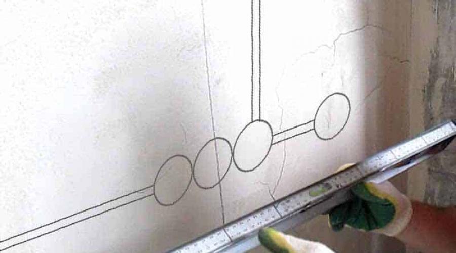
Marking on site
To transfer data wiring diagram on existing structure walls need to be used measuring instruments(tape measure, corner, etc.), level, thread and pencil. To do this they retreat required distance, according to the distances indicated on the diagram and apply the corresponding marks on building structures(walls or ceiling).
 Figure 2: Wall marking
 Markings can be done with chalk or a construction pencil. The main requirement for applying an image is to ensure good visibility and the absence of unnecessary details. In the presence of laser level this procedure is greatly simplified.
What elements need to be selected?
Structurally, electrical wiring in a house may include a number of elements:
Wires– for installation in the house, brands such as AVVG, PSV and the like are used. Copper wires are the most preferred due to the best technical parameters: long service life, less resistivity etc. But, in some situations, they can also be used aluminum wires for electrical wiring. The specific option is selected based on the maximum load and insulation requirements.
To determine the maximum currents flowing through electrical wiring, add up the power of electrical appliances that can be connected, and add 20 - 30% for the safety margin. Based on this, the appropriate cross-section of the core is selected. The insulation resistance must correspond to the characteristics of the room in which the cable is used and the installation method. It should be noted that the cables must be planned with a margin, since at the points of connection or output points they use more than the calculated length of the wire, and the margin must provide the possibility of reconnection.
 Rice. 3. wires for wiring
 – designed for connecting different sections of electrical wiring, separating and distributing electricity. They are divided into models of external and internal placement, which are selected in accordance with the project. Depending on the cross-section of the wires, boxes with the appropriate size of holes are selected.
 Figure 4: Junction boxes
 Sockets– may differ design features: presence or absence of grounding contact, cover, hole size, etc. Also various models may be intended for internal or outdoor installation. Some options have paired connection point pins.
Switches– can have a design with one, two or three keys, rotating mechanism or sensor. It should be noted that some switches are equipped with a voltage divider, which can affect the operation of lighting fixtures.
Lighting– sold as lamps, chandeliers, spotlights, sconces and others. A wide variety provides the opportunity to choose for installation in certain rooms. By purpose, we can distinguish between high-power and low-power lighting devices for the bathroom, kitchen, etc.
Devices protective shutdown – presented on the basis of electromagnetic, semiconductor or microprocessor circuits. The installation is necessary to protect both the electrical wiring in the house from short circuits and fires with those connected to it. household appliances, as well as people who may be harmed during a breakdown.
Metering devices– monitor energy consumption. Their installation is required for a new electricity connection or if this is provided for by the project. Depending on the number of phases, electric meters can be connected to a three-phase or single-phase network.
 Rice. 5: Typical electricity meter
 Protective grounding– must be provided for all consumers with a voltage of more than 42 V. Because of this, when connecting new wiring, it is necessary to have a grounding loop to which the PE conductor from all consumers is connected.
Cable channels– required for external installation of wiring; according to the material of manufacture, they can be plastic or metal boxes. The size is chosen so that when laying the wires, all the necessary conductors can fit freely in them. Structurally, they can have perforations for cooling or be made in one piece.
The procedure for installing electrical wiring in the house step by step
Please note that depending on specific situation, one or another installation operations may not be fulfilled.


First make a small hole in the center with a drill, and then use a hole saw.
 Figure 9: Drilling a hole with a crown
But at the same time, make sure that excessive force does not damage the insulation.

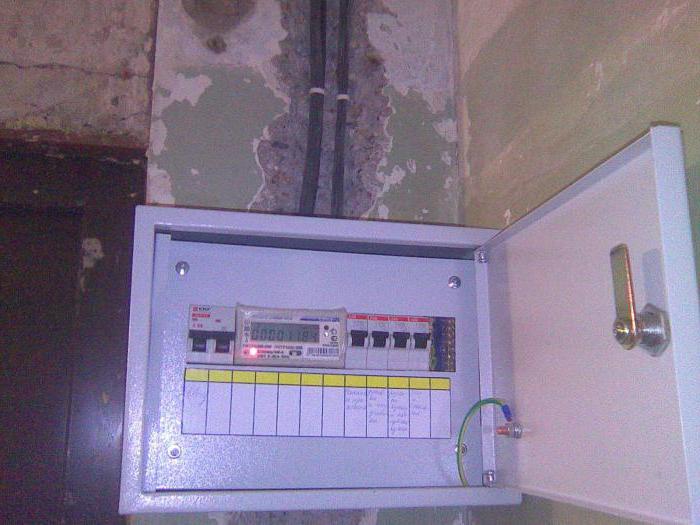
In addition to those allocated for separate rooms or objects, it is necessary to install an input machine with a higher setting. It is installed at the entrance of electricity into the house. You can also use other protective devices (voltage, differential, etc., if needed).
 Figure 15: Shield with various protections
To do this, apply voltage at the cable input to electrical panel. Then test the flow of electric current at all connection points using warning lamp or test the potential using an indicator.

If your home is not yet connected to an external network, then you do not need to do this yourself. Since the connection to the air main is carried out by employees of the energy supply organization. Performing this procedure yourself is prohibited and extremely dangerous.
Video master classes on the topic
WITH electrical installation work in the private sector in our country it is more bad than good. For most would-be electricians, protecting people from electric shock and property from fire, unfortunately, means nothing. At the same time, one gets the impression that ordinary users skipped physics classes at school and do not understand at all what it is electricity. But they believe very well in marketing tricks and happily attack “branded” automation, rejecting any other.
I propose to understand step by step all the issues of private power supply country house using the example of single-phase input. This guide can also be applied to apartment use. I would like to note right away that my specific solution for certain nodes is the optimal balance between functionality and price, but without compromising security!
I hope there is no need to retell full course physics and explain what alternating electric current is. We will also omit the moments of how this electric current appeared at the power plant and entered the power line through a step-up transformer. I'll just note that important nuance that the entire power supply system in Russia is three-phase. The single-phase voltage of 220 volts in your outlet is only phase voltage on one of the three phases. And the line voltage will be 380 volts. This circumstance should be taken into account in view of such a phenomenon as “phase imbalance”, which, nevertheless, is relevant only when old wiring, not designed for modern loads.
2. So, a step-down transformer in SNT. Comes on three wires high voltage 10 kV. Then 4 wires (3 phase and one neutral conductor) diverge along the SNT. In the photo you see a modern transformer and taps in the form of SIP wires. At the moment, the air lines in our SNT are undergoing modernization.
3. With single-phase input, two conductors are connected to each consumer: phase and neutral. In the photo you can see old aluminum wires on the pole closest to the house. The outlet to the house has already been made using SIP wire. Particular attention to the fact that all supports overhead line must have re-grounding of the neutral conductor (top right photo). This is necessary in order to eliminate emergency situations, such as “zero break”. In this case it follows with special attention treat your own grounding in the absence repeated grounding on intermediate supports, otherwise in emergency situation your own grounding may be the only one for the entire village.
4. Get to the point. The last section of the overhead line from the nearest pole to the building is stretched with SIP wire, in our case 2x16. It stands for self-supporting insulated wire; it is aluminum with a cross-section of 16 mm². For ease of installation and installation in the place of anchor fastening, using special clamps (the SIP wire implies installation of the line under voltage, on special clamps the nut is not under tension, and also has a break thread that guarantees the required tightening force) goes into VVG cross section not less than 10 mm². It is in this form that the two wires enter the input panel. In the panel we have an input two-pole circuit breaker and a surge suppressor (required at the final support for overhead input), which will protect the network when lightning strikes the phase conductor of the overhead line. It is connected in front of the machine to the phase conductor. Here in the panel the grounding is connected strictly BEFORE the input circuit breaker. We are considering the TN-C-S grounding scheme, since the TT system is still created for mobile buildings, and not permanent structures, and it has its own specific safety requirements. Disadvantages of the TN-C-S system when correct installation No. Even if we go deeper into this topic, if you make a TT, then this will only be your end section, while the entire overhead line from the transformer will be TN-C.
5. Mandatory grounding. Three corners with a wall of 50 mm (steel thickness 5 mm), 2 meters long, are driven into the ground with a sledgehammer and welded together in the shape of a triangle. A steel strip 40 mm wide goes to the wall of the house. The last meter to the shield is done using a copper conductor with a cross-section of at least 16 mm². It is strictly forbidden to underestimate the cross-section; in the event of any accident on the line, your grounding may become the only one for the entire line/street/block. The switching in the panel is as follows. The combined PEN (Protected Earth + Neutral) conductor from the overhead line is divided into two busbars into N and PE. After this it is switched introductory machine, next to it is a surge suppressor. From the machine the power line goes to electric meter. A three-wire cable goes directly into the house copper wire with a cross section of each core of 6 mm². The phase and neutral conductors come from the meter, grounding from the corresponding bus.
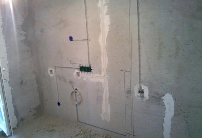
6. Let's move on to internal wiring Houses. I repeat that when designing electrical network the principle of reasonable sufficiency was used. Of course, it was possible to make 2 times more sockets and increase the number of power lines by the same amount, but I believe that this is completely unnecessary. Explanations for the diagram: red squares - distribution boxes, yellow circles - lamps. Blue indicates wiring in the screed, red - in the walls. Used everywhere in the house LED lightening(the total consumption of all lamps turned on at the same time does not reach 300 watts). The lighting is powered from the power line to a specific room, I don’t see any practical need for separation, and besides, it significantly increases the volume installation work. The diagram shows all existing consumers in the house. If you have questions, ask.
7. So, let's get started. This is a temporary electrician for the period construction work. Let's move on to laying power lines. There are 10 of them in total. Some of them will go along the walls, some in the floor in the corrugation.
8. Let's start with the floor power lines. We use NYM cable with a cross-section of 3x2.5 mm² in corrugation (the gray corrugation does not burn at all, the black one does not support combustion and has ultraviolet protection - it doesn’t really matter what to use in the screed, it’s not so easy to find a durable gray one, but I would trample the soft one while the preparatory work was underway work). A frequently asked question - why not VVG? From point of view performance characteristics they are completely identical, but NYM has the advantage of triple insulation, while it also has the disadvantage of a non-UV resistant shell. Therefore for open wiring VVG is preferable. In other respects, NYM is more convenient, including because of its round shape(round VVG also exists, but it is extremely difficult to find it in stock). A round NYM can be easily pulled into a corrugation with a diameter of 16 mm, which is extremely convenient. As a keepsake, it’s worth documenting the routes for laying lines along the floor, although nowhere except for door thresholds is there even a theoretical probability that you will need to drive something into concrete screed floor.
9. Corner of the kitchen area. Aerated concrete is simply an excellent material for processing - you can even scratch the walls with an ordinary screwdriver. So, we drill holes for mounting and distribution boxes. The wire in walls made of NON-COMBUMBABLE bases is laid in the form in which it is. No corrugations are required. All attention to the tracks. Power lines are laid only at right angles. The main line runs along the floor at a height of 20-30 cm, then rises strictly VERTICALLY to sockets and switches. Diagonal laying is prohibited and is dangerous with the risk of getting into the wire, for example, when driving a nail into a wall (and so you know for sure that you cannot drive nails exactly under sockets and above switches). The cable is attached to the wall using plastic round brackets (two holes are drilled and the bracket is inserted).
10. The floor screed is filled. The question at what stage to lay the cable along the wall is purely a matter of your personal preference. Someone first plaster the walls, then make a groove, lay a cable and seal the groove back. I prefer to do the wiring before plastering the walls. This method may seem inconvenient because... extra attention will be required during plastering works to points with mounting boxes(you need to plug them up with something and then pick them out). Pay attention to the left corner - all switching on the pass-through lines of sockets is made not in socket boxes, but in separate distribution boxes.
11. I will repeat with the type of wires. NYM is an ideal and universal cable. The cross section is selected in accordance with the load. Usually a 3x2.5 mm² cable is used. For powerful consumers, such as an electric hob, a wire with a core cross-section of 4 mm² may be required. For lighting lines, where in my case LEDs are used (maximum power consumption in the most big room 80 watt) I use a PUNP cable 2x1.5 mm² (grounding in lighting network no need, there is nowhere to connect it). In general, regulations prohibit the use of PUNP due to the fact that technical specifications allow the cross-section of the cores to be underestimated by up to 30% compared to the standards, and with widespread savings everywhere and in everything, this can cause a fire due to excess permissible load. In my case, my maximum load more than 30 times less than what a cable with a cross-section of 1.5 mm² can safely pass through. Therefore, a larger cross-section is not required, and this cable is most convenient for installing a lighting line. Yes, keep in mind that for fixed wiring only rigid cable with a single core is used. Socket boxes and distribution boxes are mounted in the wall on building gypsum(alabaster), as the fastest drying solution.
12. Now comes the actual stage of assembly and installation of power lines. It will take several convenient tools. The uppermost one is used for crimping the ends of multi-core cables, for example PV3 (currently being replaced by PuGV), which are used when assembling an electrical panel. The middle tool is useful for quick stripping NYM cable sheath - clamped, turned, pulled. Below is a simple tool for stripping the end cores, not very convenient, but more than enough for a one-time job.
13. It is also necessary to have such a thing as an indicator screwdriver. There are two varieties of them. Original device with neon light bulb without a power source, it can only detect phase voltage. This simple Chinese device with a power supply has more advanced functionality and allows you to determine not only the phase (important! to determine the phase, you must not touch the screwdriver cap with your fingers), but also the integrity of the line, as well as the location of the conductor break. On the right is the initial blank for the electrical panel. When switching, it is important to distribute everything in such a way that it is intuitively clear where everything is.
14. I’ll immediately note a nuance that “experts” will definitely get to the bottom of - the neutral conductor must be of blue color, and I have it black because in our tree called Moscow there is never anything available at the moment when I need it (since the shield is obviously single-phase, there is no obvious catastrophe and error of confusing zero with the second phase). For switching in the electrical panel, I use a PV3 wire (you can use a modern PuGV) with a cross-section of 6 mm². It will also require special NSVI lugs (insulated pin sleeve lug), they are needed in order to assemble stranded wire before switching under the screw (the cores will spread out - there may be poor contact). It is also convenient to use special single-pole and double-pole busbars (in the right photo in the background) to connect a number of circuit breakers.
15. Switching in distribution boxes is as follows. The terminals used are WAGO 2273 (left) on conductors with a cross-section of 3x1.5 mm² (why and why - below) and WAGO 222 (right) on conductors with a cross-section of 3x2.5 mm². Always follow color coding conductors. WAGO 222 series perhaps best option, if you don’t want to bother with soldering and crimping.
16. Installation of sockets and switches. I really like Schneider Electric products, the Unica series. According to modern standards, switches must be turned down. Switching upwards is an old school from the time of switches, the switching of which upwards was due to their design. Unica series switches are switched downwards, this is their standard position.
17. Switching of double sockets standing next to each other is as follows. Power wire comes to the terminals of one socket, and then a branch is made to the adjacent one. Rules good manners when installing sockets, it is prescribed to connect the phase conductor on the right.
18. We return to the electrical panel. I would like to draw your attention right away - always take a shield with a very large reserve, it will definitely not be superfluous. I seemed to have done everything to the minimum, but almost all 36 positions (3 rows of 12 positions each) were occupied. Be sure to leave a supply of power line wires equal to at least one and a half times the height of the shield. On the right you can see the first version of switching, but in fact this is the moment when the house was switched from temporary electrical diagram permanent. In the process, a couple of consumers appeared and the scheme was slightly modified.
So, I’ll tell you in detail what, how and why. Go!
A few words about the components of the shield.
Automatic switch or just a machine. Provides protection from short circuit, and also provides protection for electrical wiring. Consequently, it contains two releases - electromagnetic and thermal, respectively. The first one is triggered in the event of a short circuit on the line; the response time is determined by the time-current characteristic, which in any case is several times higher than the current rating of the machine. The thermal release is a bimetallic strip with different coefficients of thermal expansion and is designed to protect electrical wiring. It is in accordance with the cross-section of the cable and the sockets used that the rating of the machine is selected. The most popular mistake is to put on power line with a 2.5 mm² wire, a 25A automatic, based on what the cable can withstand. No you can not. And the reason lies in the sockets. Regular sockets designed for current up to 16A. Therefore, this is exactly what the machine’s nominal value should be. And in general, it is better to play it safe and reduce the rating of the machine, as it will be the one that can protect the wiring from overheating or, even worse, fire.
An RCD is a protective device that detects leakage current. The simplest mechanical device which is a differential current transformer. To put it simply, the amount of current that “arrived” through the phase conductor should be equal to the amount of current that “went out” through the neutral conductor. If “out” is less than “in”, there is a leak and protection is triggered. If there is grounding, the RCD will operate as soon as the dangerous voltage, if there is no grounding, the RCD will trip as soon as a person touches the housing (he will get a slight electric shock). It follows from this that RCDs should always be used, and the presence of grounding only increases the level of safety. At the same time, it is strictly forbidden to make homemade grounding in an apartment in the absence of it; the consequences can be very sad. About the RCD, it is worth noting that it itself needs to be protected from short-circuit current, so after it in the line there must be a circuit breaker(s) with a lower rating than the RCD itself. The rating of the RCD itself implies what maximum current it is designed for; it is better to focus on a 20-30% margin from a constant load. The simplest way Check the functionality of the RCD and the correct grounding - close the neutral and grounding conductors in the socket. The RCD should turn off immediately.
Summarizing: circuit breaker protects wiring and equipment, RCD protects people. There are also difavtomats (here and earlier I use the terminology that has developed in our country, although it is not entirely accurate), a device that combines the functions of an automatic machine and an RCD.
Now let's move on to the shield:
Let's start from the left top corner. This is where the 3x6 mm² cable comes from the street panel. Input RCD with leakage current 300 mA. Popularly called “fireproof”. It is used in conjunction with an RCD for a lower leakage current, firstly to ensure selectivity during shutdown (first of all, the “junior” RCD will trip), and secondly, to increase fault tolerance. Next to it is the ABB C11 meter, which I use exclusively for technical metering of electricity (to report to you the figures for air consumption heat pump and don’t run to the street sign to do this). There are two after it two-pole circuit breaker also acting as switches. The left one, rated at 40A, is used to de-energize the entire electrical system home except for an air source heat pump. The right one controls the air source heat pump). To the right there is a thermostat for the anti-icing system (20 meters of heating cable in the gutter and drains) and three automatic devices: for it and two lines of street outlets (which in turn are powered by one RCD from the next row).
Second row. In the left corner there is a common ground bus for all lines. Pay attention to the switching. You should not lay wires behind the slats; it is better to route them as openly as possible. Next we have a line of RCDs in the amount of 6 pieces, according to which all consumers in the house are evenly divided. The leakage current of all RCDs is 30 mA, although ideally for a bathroom it is worth using an RCD with a leakage current of 10 mA.
Third row. Finite state machines consumers along the lines. On the left, right and bottom there are corresponding zero buses extending from a specific RCD for each line. They must be separate, otherwise there will be no point in dividing the RCD into separate lines. The machines are grouped into groups according to load types.
How to choose rated current automatic? As we explained above, the rating of the machine is selected based on the cross-section of the conductor (a copper conductor with a cross-section of 2.5 mm² can withstand 25A long-term load) and switching devices ( household sockets designed for current up to 16A). Everyone knows how to convert amperes to watts - multiply by voltage (220 volts).
20. Close-up bottom row of machines. Single-core cables are connected directly to the screws; multi-core cables must first be crimped with a lug. There are a lot of unfounded claims from “experts” about IEK products, and very in vain. This great option in terms of price/quality ratio. They are made in China, Russia and Turkey. And they perform their function no worse than the “racially loyal” ABB and Legrand. Don't believe me? Ask real electricians, not charlatans selling what is more expensive. All of Moscow, after the recent modernization, is electrified using IEK automation; of course, on a scale of millions, the quantitative statistics of failures will be higher than in the case of other brands, which are used in the housing stock by several orders of magnitude less. What bad can happen to IEK? And nothing that can harm a person. Once triggered, the RCD or circuit breaker simply will not turn back on and will require replacement. That's all.
21. Assembled shield assembly.
22. And a layout along the lines with signatures. Simple and functional. Groups along lines are highlighted in color. If an accident occurs, for example on a line with a pump, then only it will turn off, and the power supply to the entire house will not be affected. This number of RCDs may seem excessive to many. Indeed, a sufficient minimum is one incoming RCD for the entire facility with a leakage current of 30 mA. Remember - there should always be an RCD. Even if your apartment does not have a modernized input and uses a TN-C connection with two wires. Yes, you do not have a separate grounding, and the RCD will not handle the situation of phase leakage to the device body without the “help” of a person. But the RCD will protect the person.
23. Well, the final types of sockets in the premises. Let me remind you that on outlet lines the circuit breaker should not exceed the rating of 16A (for example, the line to the bedroom is made with NYM 3x1.5 mm² cable (I don’t see the need to include a load of more than 2 kW there), and therefore the circuit breaker on this line has a rating of current 10A.
24. And a few words about lighting. Everywhere in the house there are inexpensive lamps chambered for GU10. From LED lamps I ordered several models from China for testing, and also took “Russian China” ones under the Camelion and Woltra brands. With the price of the latter being about 230 rubles per lamp, I’ll honestly say that buying anything from China is pointless. All samples priced at less than 150 rubles apiece have a serious spread in color temperature, not to mention too low (Ra<70) индексе цветопередачи.
Everything related to electrical networks is described in detail and clearly in the PUE (Electrical Installation Rules). There are some differences between chapters, but overall everything is correct.
Have questions? Ask!
Need help with electrical work? Contact us!
Construction partners:
Designing electrical wiring in a private house is quite a troublesome task, but quite feasible even without special knowledge. It is enough just to approach this issue carefully. Well, our tips given in this article will allow you to step by step create your own electrical wiring project for any private home.
Any development of an electrical network project begins with determining the total power of the consumer, in this case our home, and its power supply circuit. And if the total power of the consumer in our case is determined by the energy supply company, which sets a consumption limit, then we have the right to design the internal electrical network diagram ourselves.

So:
- The electrical wiring in a private house is as follows. The energy supply company installs an input machine and a meter on the outside wall of the house. The connection of these electrical devices is also carried out by the energy supply company.
- But after the meter, we do the entry into the house, connection to the distribution board and wiring around the house ourselves. And here we have the right to choose a power supply scheme that is convenient for us.
- Typically, a home's power supply diagram looks like this. The cable or SIP wire from the meter is connected directly to the busbars of our distribution board. Separate power supply groups are powered from these buses. Each group has its own power circuit breaker installed on the phase wire. The neutral and protective wires of each group should not have switching devices.
Note! The neutral wire of individual groups can have a switching device only if connected through an RCD. The RCD can be installed either on a separate group or as an input for all groups. The issue of choosing the location for installing the RCD is not regulated by the PUE norms and remains a controversial issue. But based on operating experience and the personal opinion of the author of these lines, we advise you to install them separately for each group.
- Next, the wire or cable from each group machine is mounted to the distribution boxes. Each group can have from one to several distribution boxes.
- From distribution boxes, electrical wiring is distributed to end consumers - sockets and switches.
Designing a home electrical network
Based on the above general diagram of the house's power supply, to design the electrical network, we first need to calculate the number of groups and distribute the loads among them. In order to do this, we need to decide on the wiring installation method and calculate the possible load of our consumers.
Choosing a wiring installation method
Let's start by choosing the method of installing the electrical network. Electrical wiring of a private house can be done in an open or hidden way. And not only the number of groups, wire cross-section and total installation cost, but also the appearance of the entire house depends on the right choice.

So:
- First of all, we note that any type of wiring installation can be implemented in a house of any design and from any building materials. The only question is the cost of installation work. We will not provide installation standards for different types of wiring in different conditions. You can find this information in other articles on our website. Let's focus only on generally accepted norms.
- Open wiring has found wide application in houses made of flammable materials. First of all, this is wood, SIP panels and other types of combustible building materials. For such houses, the price of installing open wiring is often much lower. Hidden wiring will require considerable financial investment, and its installation is labor-intensive.
- Hidden wiring is used mainly in houses made of brick, foam blocks and other non-combustible materials. After all, this type of wiring allows you to completely hide utility networks, while at the same time, in houses made of non-combustible materials, it does not impose any special requirements.
Calculation of the total load of the house
At the next design stage, you need to calculate the total load on the house and on individual electrical receivers. This is necessary for the subsequent formation of groups.
- To do this, we first need to determine the number of electrical points and their maximum power consumption. This often becomes the most serious problem for non-professionals, but de facto there is nothing difficult about it.
- Each socket or switch in the house is mounted for a specific electrical appliance or group of electrical appliances. We just need to select the most powerful of them and then carry out calculations for it.
- The power of an electrical appliance can be viewed in the device passport. It may also contain an instruction manual. If you don’t have one or the other, then you can find out the approximate power in our table.

- But in most cases, the power of devices is indicated in Watts, and we need to convert it into Amperes. To do this, you can use Ohm's law - . In general, this is a simplified version of the formula, but for our purposes it is quite sufficient. Based on this formula, it turns out that an electrical appliance with a power of 1 kW for a 220V network consumes an electric current of approximately 4.5A.
Distribution of loads by groups
After we have calculated the total load in the house and for each individual electrical point, we can begin to directly create groups.
So:
- According to clause 9.6 of VSN 59 - 88, the rated power of circuit breakers for powering group lines of sockets and lighting networks should not exceed 16A. Starting from this point, we distribute our loads into separate groups.
Note! To power powerful electrical receivers such as an electric oven, it is allowed to install group circuit breakers with a rating of 25A.
- Load distribution among groups should be based on their location and type of load. So quite often the group lines of the lighting network are separated from the power supply groups of the sockets. But this is not mandatory, and in some cases it is not advisable.

- It is also worth remembering that it is not easy to install electrical wiring in a private house yourself. Therefore, you should not place different electrical receivers of the same group in different parts of the house. Usually these are 1 - 2 adjacent rooms.
- Another aspect that is worth paying attention to is clause 7.2 of VSN 59 - 88. It requires connecting sockets in the kitchen and living rooms to different groups. Quite often, the kitchen outlet group also includes an outlet in the bathroom.
Note! Sockets in the bathroom can only be installed if there is an RCD circuit breaker in the group in which the socket is installed. Moreover, according to the PUE, the rated leakage current for such a switching device is normalized by a leakage current of 30 mA.
- As a result, we can get from 3 to 7 groups depending on the total load. Some may end up with more than 10 groups. But here everything depends on the size of the house and the number of electrical appliances. But according to the technical conditions, the introductory circuit breaker, which is installed in a house, rarely exceeds the value of 25A, sometimes 40A.
- This should be remembered when dividing the load into groups with your own hands. After all, the likelihood that all electrical appliances will work at the same time is quite low. Therefore, you should approach this issue soberly and perform the distribution more carefully, taking into account such a factor as the utilization rate.
Wiring selection
Before you carry out electrical wiring in a private house yourself, you should also worry about calculating its cross-section. After all, its durability and fire safety depend on this factor. This issue is especially relevant for houses made of combustible materials.
- According to clause 7.1.34 of the PUE, only copper cables and wires should be used in residential buildings since 2001. Previously, aluminum wires, which can often be found in old houses, were allowed.
- As for the cross-section of the wires, it should be selected based on the load on the group line. But in order to avoid making a lot of calculations and simplify the choice, you can proceed from the nominal parameters of group machines.
- In addition, when choosing a wiring cross-section, you should take into account the method of laying the wires. After all, the heat transfer for wires laid in a hidden and open way is different. In this regard, although slightly, their cross-section differs depending on the load.
- We make the choice according to Table 1.3.4 PUE. In addition to the loads and installation method, it also takes into account such a parameter as the type of wire.

- But no matter how you choose the electrical wiring in a private house, you should remember that the cross-section should be no less than that given in the table. 7.1.1 PUE. For group lines it must be at least 1.5 mm 2.
Conclusion
In our article we presented the main stages of designing an electrical network in a private home. As you can see, there is nothing complicated about this, and the video on our website should make this task even easier. The main thing is to approach this issue carefully and carefully and you will probably succeed.
In the article we will talk about how to do electrical work in the house with your own hands; wiring diagrams will also be considered. If a couple of decades ago the load on the electrical networks of cities and even villages was insignificant, today the picture is the opposite. There are a lot of high-power household appliances - washing machines, multicookers, split systems, etc.
The load on electrical networks has increased many times. And while urban wiring has some reserve, the wiring of a private house does not have this, therefore, an increase in load leads to the fact that the wires cannot withstand and begin to collapse. Consequently, the question arises that the electrics in the apartment and house should not only be repaired with their own hands, but also changed completely.
Previously, wiring in houses was done according to the simplest scheme - a switch and socket for each room, but in modern conditions this turns out to be too little - you want to turn on three chargers, a laptop, a TV, and so on. To do the wiring in your house yourself, you need to know certain rules and standards that should be followed during installation. You will also learn how to make a wiring diagram, how to wire it correctly with your own hands, and the requirements for it.
Regulations
Construction materials and all activities of builders are regulated by certain rules and requirements, they are called GOST and SNiP. The Electrical Installation Rules (hereinafter PUE) also apply to electrical wiring in houses and buildings. It is this regulatory document that prescribes all the requirements for electrical equipment, thoroughly indicating what to do with it and how. All electrics in the apartment and house are connected to voltage with your own hands only after all checks for short circuits have been carried out.
Requirements for electrical wiring in private houses and apartments

If you decide to make the electrical wiring in your home yourself, you need to carefully study all the requirements for it. But the main attention should be paid to the following points:
- The main components of electrical wiring (distribution boxes, switches, sockets, meters) must be made easily accessible. It is quite easy to install wiring in the house with your own hands. Electrics, however, are demanding from a safety point of view. But all the rules can be easily followed.
- According to the PUE, switches must be installed at a level of 0.6-1.5 meters from the floor surface. Moreover, you need to pay attention to the fact that when opening the doors they should not create an obstacle. For example, if the door opens to the right, then the switch should be located on the left. And if the door opens to the left, then the switch is mounted on the right. The cable must be routed to the switch from above.
- Sockets are mounted at a level of 0.5-0.8 meters from the floor surface. The fact is that it needs to be located at this level for safety reasons when the house is flooded. Moreover, a distance of at least 0.5 m must be maintained from a gas or electric stove, heating radiators, pipes (and other objects that are grounded). The wires go to all sockets from bottom to top. This is exactly how you do it yourself. Wiring diagrams are given in the article.
- For every 6 sq. m. area of the room there should be one socket. The exception is the kitchen, in which as many sockets are installed as necessary (based on the number of household appliances located in it). It is prohibited to install sockets in the toilet, but in the bathroom it is allowed only if there is isolation through a transformer (220 Volts are supplied to the primary winding, and the same amount is removed from the secondary winding). The transformer is installed outside the bathroom.
- Before starting work, you need to make a wiring plan and clearly indicate its location in the walls. Please note that all wires must be located either horizontally or vertically - but not diagonally or in a broken line. This is not how you should do the wiring in your house yourself. The connection diagram of all devices must take this feature into account.
- There must be a certain distance from ceilings, pipes and other obstacles. For example, you need to maintain a distance of 5-10 cm from the beams, and the same from the cornices. You need to maintain approximately 15 cm from the ceiling, 15-20 cm from the floor. If we are talking about vertical surfaces, then there should be at least 10 cm from door and window openings. But between the gas pipe and the wiring you need to maintain a distance of more than 0.4 m.
- External or hidden wiring should not touch metal parts of any structures.
- If several wires run in parallel, the distance between them must be maintained in excess of three millimeters. An alternative option is to hide each wire in a protective box or corrugation. This is how you install electrical wiring in a house yourself. Schemes should be drawn up with this in mind.
- Wires should be connected and routed in special distribution boxes. All connection points must be carefully insulated, and one feature must be taken into account - it is prohibited to connect copper and aluminum wires. If you make wiring from copper wire, then make it all from it, there should not be any sections made of aluminum.
- Grounding (including zero wires) must be secured to all devices using bolted connections.
These are the requirements that all electricians ask for. You can create connection diagrams with your own hands only if you take into account all these rules and regulations.
House electrical wiring project

The first thing you need to do is create an electrical wiring project, this is where it all starts. You will use it as a starting point during installation. Of course, it will be much better if it is done for you by experienced technicians who have been involved in this business for many years. But if you have experience, go for it.
But keep in mind that your safety depends on how the project is made. You definitely need to know what conventions are used when drawing up diagrams and projects. It is worth noting that Russian standards are quite different from European or American ones, so you should not use foreign schemes in the conditions of our country. All electrical installations in the house are designed with your own hands (diagrams are given in the article) at the initial stage.

Draw a plan of a house or apartment, mark on it the places where sockets, switches, chandeliers, etc. will be installed. The number of electrical appliances was discussed a little below. At this stage, the main goal is to create a diagram on which all the installation locations of the devices will be indicated. The second part is to outline the places for laying wires around the apartment. Of course, you need to know in what places the household appliances will be placed.
Wiring
Then wire all the wires. And if creating a diagram with the location of consumers is a simple matter, it is worth going into more detail at this stage of work. Three types of connections and wiring can be used:
- Consistent.
- Parallel.
- Mixed.
The third one is considered the most attractive from the point of view of saving materials.

Do-it-yourself electrical work in the house (mixed type circuits) with the highest possible efficiency. To make your work easier, ungroup:
- Lighting of corridors, living quarters, kitchens.
- Bathroom and toilet (lighting).
- Sockets in living rooms, corridors.
- Sockets in the kitchen.
- Electric stove socket (if necessary).
Please note that this is the simplest option for grouping electricity consumers. The fewer groups, the less materials will be used. The above example is the simplest and most economical. You can make it more complicated: literally connect electrical wiring to every outlet, for example. You begin to understand a little about how to install electrical wiring in a private home with your own hands.

To simplify the installation of electrical wiring, it can be mounted under the floor (for sockets). In the case of overhead lighting, installation can be carried out in floor slabs. Ideal for the “lazy” method - there is no need to groove the walls and ceiling. Moreover, on the plan diagram this type of wiring should be marked with dotted lines.
Calculation of current consumption
It is imperative to take into account the current strength that will flow through the network. There is a simple formula for this: current strength is the ratio of the total power of all consumers to voltage (we can say that this is a constant, since the voltage standard in our country is 220 Volts). Let's say you have the following consumers:
- Electric kettle with a power of 2000 W.
- A dozen incandescent lamps, each 60 W (total 600 W).
- Microwave oven with a power of 1000 W.
- Refrigerator with a power of 400 W.

The mains voltage is 220 V, the total power is 2000+600+1000+400, that is, 4000 W. Dividing this value by the network voltage, we get 16.5 A. But if you look at practical data, in apartments and houses the maximum current consumption rarely reaches 25 Amperes.
Based on this parameter, it is necessary to select all materials for installation. In particular, it depends on the current strength. Please note that you should always take a margin of 25%. In other words, if you have calculated a current consumption of 16 A, you cannot install a fuse with the same trip current value. You need to choose a standard value greater than the calculated one.
Wire brands for home use

Now let's talk about how the electrical system is installed in the house. The cable (the PUE rules regulate all its parameters) must be selected based on the current characteristics. It is advisable that the wiring in a house or apartment be made of the following materials:
- Wire brand VVG-5X6. This wire consists of five cores, each with a cross-section of 6 square meters. mm. It is widely used for houses that have a three-phase network to connect the lighting panel to the main one.
- VVG-2X6 has two cores with a cross section of 6 square meters. mm. Widely used for single-phase power houses to connect the lighting panel and the main one.
- The VVG-3X2.5 wire has three cores, each with a cross-section of 2.5 square meters. mm. Used to connect lighting boards with distribution boxes. Also from boxes to sockets.
- Brand VVG-3X1.5 has three cores, each with a cross-section of 1.5 square meters. mm. Used for connecting switches and lighting lamps.
- Brand three-core, cross-section of each core 4 sq. mm. Used to connect electric stoves.
Material Quantity Calculations

Now you consider what components (including small ones) the electrical wiring in the house consists of. Do-it-yourself project, wiring, installation, is done quite quickly. True, you will have to try hard to count the amount of wire as accurately as possible. To do this, according to the plan, walk around the apartment with a tape measure. After taking measurements, add four meters on top - there will be no excess margin.
At the entrance to the house all the wires from the house go to it. It installs automatic switches. Please note that the machines must have a maximum operating current of 16 or 20 Amps. must be connected via a separate circuit breaker. With a power of up to 7 kW, a 32 A automatic machine is used, with a higher power - 63 A.
Then you count the number of distribution boxes and sockets, there is nothing complicated in this matter, this is done according to the diagram drawn up earlier. In the future, you will need various “little things”, for example, insulating tape, lugs, tubes, cable ducts, boxes, thermal insulation, and others. Now it’s worth talking about what tools are used to install wiring in a house with your own hands. The scheme is discussed in some detail.
Tools for work
When carrying out, always adhere to safety regulations. In order not to get confused, it is better to do it yourself, but if you have a partner, then the help should be minimal - give it, bring it, don’t interfere. You will need the following tool:
- Multimeter.
- Hammer.
- Bulgarian.
- Screwdriver.
- Pliers.
- Wire cutters.
- Curly and flat screwdrivers.
- Level.
If you are renovating an old apartment and at the same time changing the wiring, you need to pull out all the cables so that they do not interfere. For this work, a special electrical wiring detection sensor is useful.
Marking the location of wires
Place marks on the wall where you will route the wires. Pay attention to whether the position of the wires complies with the rules. After you have marked the places where the electrical cables will pass, you can mark out the sockets, boxes, panels and switches. Please note that in new apartments there is a niche for installing the shield. And in old houses, the panels are simply attached to the wall.
Wall scoring
First of all, install a special attachment on the hammer drill and drill holes for installing distribution boxes, switches and sockets. To lay wires, it is necessary to make grooves in the walls - grooves. They are made using a grinder or a hammer drill. Whatever method you choose, there will be enough dirt and dust. The groove should have a depth of 2 cm. As for the width, it should be enough to lay all the wires. As you understand, doing electrical wiring yourself is a simple matter; from a physical point of view, it is more difficult to do the installation.
A separate story with the ceiling. If you plan to make it hanging, then simply install all the wires on the ceiling. This is the easiest way. It’s a little more difficult to make a shallow groove. And one more thing - hide it in the ceiling. For example, in panel houses, floors are used in which there are internal voids. Therefore, two holes are enough to route the wires. And the last thing is to punch holes in the corners of the rooms to bring the wires to the central panel. Then you proceed to closed (you will have to groove the walls) or open methods.
Conclusion

The most important thing in installing electrical wiring in houses and apartments is to adhere to all norms and rules in accordance with GOST, SNiP, PUE. This way you can not only achieve maximum efficiency from electrical wiring, but also reliability, durability, and most importantly, safety. And try to use only high-quality materials during installation. For example, it is advisable to use copper wires - they have a much longer service life (better conductivity, heat less).
Recently, capital and dacha construction has become very popular. Many homeowners prefer to create their dream home themselves, without resorting to the services of companies.
Without electricity, the life of a modern person is unthinkable. Therefore, power supply to the home is the homeowner’s first priority.
People who decide to build a house with their own hands are faced with the need to electrify it. It also happens that in existing housing the electrical wiring is in very poor condition and needs to be replaced.
We will consider all the nuances of connecting your home to the electrical network, installing different types of electrical wiring, and study in detail common mistakes in order to avoid them in practice. The article will also contain instructions for commissioning wiring and recommendations on popular issues.
General rules for connecting to the electrical network
Regardless of whether you want to connect a new house to the network, or restore power supply in an old one (for example, when completely changing the wiring), you will have to undergo a lot of bureaucratic procedures. To obtain a permit you need:
- Registration of technical specifications (technical conditions). To do this, you should contact the energy supply company in your locality and the resource supply organization in charge of the electrical networks of your region). Please clarify in advance what package of documents each organization will require along with the application. You will also need to write an application in the prescribed form.
- Creating a Project. It is carried out either by a resource supplying organization or by a commercial company that has the appropriate license. Subsequently, you will need to coordinate the project with the organizations to which you applied to connect your home.
- Connecting an object. The installation work itself is usually carried out by the energy supply organization. If they did not connect the house, you will need to provide them with a copy of the license (permit to perform certain work) of the company that carried out the installation and a full list of the work performed.
- Acceptance tests. Elements of the electrical installation require testing, which is carried out by a special laboratory. Upon completion of the procedure, the laboratory issues a protocol containing data on the parameters of the equipment and a conclusion on its suitability for use.
- Verification and sealing. The electricity meter must be verified and sealed by the energy sales office. A permit for further operation of the metering device is also issued there.
- Conclusion of an agreement. At the end of all these procedures, it is necessary to provide a package of documents to the resource supplying organization, obtain permission to use its services and conclude an agreement under which the facility will be supplied with electricity and payment will be made for the resource consumed.
The best way to start installing wiring in a private house with your own hands is with a circuit diagram. This will greatly facilitate further calculations of consumables and determination of installation locations for power elements.
The wiring diagram must include the following elements:
- Supply from the nearest support to the incoming electrical panel
- Electricity meter
- Input RCD/switch
- Internal electrical panel with consumer groups:
- Rosette group
- Lighting
- Power group (high-current household appliances (boiler, washing machine, machine tools)
- Outbuilding (garage, basement)
A diagram of how to properly conduct and make electrical wiring in a private house with your own hands:
Separate RCDs/automatic circuit breakers are installed for each of these groups.
Also, when drawing up a diagram, you need to have a general plan of the house, on which to mark the direction of laying the cables and the installation locations of sockets and switches.
It would be good if the wiring had two separate circuits. Then it will be possible to turn off one for repairs, and from the second to power the necessary lighting or soldering equipment.
Based on these data, a schematic diagram is constructed, the total length of the cable is calculated, the required cross-section in each case, the placement of power elements, metering devices, and the point of entry of power cables.
What you need
Let's try to figure out how to make and install electrical wiring in a private house yourself. In order to install high-quality electrical wiring in your house that complies with all SNIPs and safety standards, you will need the following materials and tools.
Consumables
- Electricity meter
- RCD, automatic or difavtomat
- Cable of various sections (power, low-current, lighting)
- Branch boxes
- Terminal blocks (it is better to take screwless ones)
- Switches
- Sockets
- Alabaster mortar for fixing the cable in the groove
- Socket boxes
- Self-tapping screws
- Box for open wiring
- Skirting boards, if the wire will be laid under them
- Electrical cardboard
- Tin fastening strips or plastic fasteners
Required Tools
- Wall chaser (grinder with diamond discs)
- Assembly chisel
- Hammer
- Cable scissors
- Putty knife
- Emery grater
- Pliers
- Roulette
- Screwdriver
The cable is selected based on the total load. On average, this is 0.5-0.9 square millimeters per 1 kW of power. It is best to use copper stranded wire. He is better twistable, elastic, stable to short-term loads.
The number of sockets, switches and other elements is calculated when drawing up a circuit diagram. It is better to take boxes and boxes from self-extinguishing or non-combustible materials.
Hidden wiring is best done under the baseboard, and not in the groove. This position of the cable prevents it from being hit by a drill or nail during repair work; it is accessible and can be checked or reconnected.
How to properly make and conduct electrical wiring in a private house with your own hands:
Step-by-step installation instructions
Different homes recommend different types of wiring. In wooden buildings, electrical wiring is most often done in an open type, and in concrete buildings with many technological voids - hidden. Let's consider the nuances of installing and conducting electrical wiring in a private house with your own hands.
Open (external)
Often used in country wooden houses. It can be made both in special boxes, under baseboards, and in “retro style”, from a special cable and on porcelain insulators-mounts that fix vertical elements.
To conduct open electrical wiring in the house, you need:
- Calculate the length and cross-section of cables of each type: power, lighting and low-current
- Create an electrical circuit diagram
- Use flat wire brands APRV, APR, APPV
- Mark the cable route and fasten the installation elements. Remember that the distance from doors and windows must be at least 10 cm, from the ceiling - at least 20 cm. The installation height of switches and sockets is about 80 cm, but not more than 150 from the floor.
- Secure the cable to the walls with tin strips or plastic fasteners to prevent sagging.
- Secure distribution and installation boxes
- Make connections according to the diagram: put the wires into boxes with a margin of 70-100 mm and connect them
- Install sockets and switches in the places indicated on the diagram
- Connect the wires to them
Closed
Installation is a little more difficult. To hide cables in walls, you need:
- Mark the walls using a marking line
- Using a grinder, cut 2x2 cm grooves in the walls
- Use a wall chaser to cut out spaces for installing distribution boxes, switches and sockets
- Install boxes and socket boxes. Secure them with asbestos or screws and dowels
- Prime the grooves
- Place the cable in them. It must first be cut into pieces of the required length.
- Secure it in the groove with plaster. Mounting pitch – about 40 cm
- After 20-25 hours, when the plaster is completely dry, clean it
- Install switches and sockets
That's all the simple steps required to electrify your home yourself.
Step-by-step video instructions on how to do electrical wiring in a private house with your own hands:
Installation of accessories
In the now fashionable open-type retro wiring, the fittings can be very diverse. In addition to switches and sockets, porcelain insulating rollers are used there. Each piece of fittings should be fastened at the following distance:
- Insulator rollers: 10-12 centimeters apart
- Single-core twisted wire - 1 centimeter from the wall
- Sockets: no lower than 35-40 centimeters from the floor and no lower than 15 cm from the kitchen table
- Switches - from 50 to 150 centimeters from the floor
Switches and sockets must not be installed at the same level. This rule also applies to hidden electrical wiring.
Safety rules, mistakes and ways to avoid them
Sometimes homeowners neglect certain nuances or make careless mistakes that can seriously affect fire safety. We will look at the most common of these mistakes and ways to avoid them.
- Aluminum wires. They must not be used under any circumstances. They are fragile and can break off when replacing an outlet or switch. It's better to pay more, but take copper ones.
- It is prohibited to use stranded wires in hidden wiring.. The terminal does not hold such a cable very well, so a constant heating point is created. This can lead to both damage to the socket/switch and a fire.
- Do not connect wires of different metals directly to each other.. To avoid oxides, do this only through the terminal to eliminate possible metal-to-metal contact.
- Waterproofing. It should not be neglected in rooms with high humidity: bathrooms, kitchens, pantries, terraces. Failure to do so may result in electric shock.
- Mark the wire length with maximum accuracy. Placing twists on straight sections, especially if 10-15 centimeters are missing, is strictly prohibited!
- Strobe under the groove. Its depth should be 2-2.5 centimeters. There is no point in running the cable deeper, and a shallower groove is difficult to plaster.
- Distribution boxes. They should be located almost under the ceiling. This is done for ease of wiring maintenance and to avoid confusion between cables for various purposes.
- Wire cuts. They must be strictly vertical or horizontal. Possible cable savings when laying diagonally can lead to a drill or nail getting into it during repair or finishing work in the house.
- Wire size. It shouldn't be too thin. Thin wires cannot withstand the increased load and burn out. The optimal cross-section for the socket group is 2-2.5 mm, for the lighting group – 1.3-1.5 mm.
And a little about safety precautions. Work with home electrics only when the plugs are off. Electric shock can lead to the most tragic consequences.
Testing and commissioning
After complete installation of electrical wiring, you need install all planned machines, RCDs and electrical appliances. After this, feel free to invite a specialist from the energy supervision department to check and commission the electrical equipment of your home.
Acceptance testing of your facility must result in the issuance of a positive conclusion on the safety of the electrical installation carried out, the possibility of further use of the equipment. You must contact the energy supply organization with the “Connection Permit Certificate”. On this basis, she must connect your facility to the support and draw up a contract for the provision of services.
You should not skimp on consumables and tools - after all, in the future, quality work done will be the key to your peace of mind and comfort.
Do the electrical wiring in the house yourself - It’s not a difficult task, but it requires care and scrupulousness.. If you approach this matter responsibly, the wiring will serve you for many years and is guaranteed to be safe.
Source: //elektrik24.net/provodka/v-chastnom-dome/sdelat-svoimi-rukami.html
How to install electrical wiring in a house?
Installing wiring in a private home is a labor-intensive process, but nevertheless, even a novice electrician can do it! If you are determined to carry out all the calculation work yourself and have all the necessary tools at hand, or simply want to supervise a working electrician, then we will look at the entire process from A to Z. To make the technology clear even for beginners (so to speak, dummies), we will look at it step by step How to do electrical wiring in a house with your own hands.
The process consists of several main stages:
- choice of installation method (open, hidden);
- creating a diagram;
- marking works;
- selection of constituent elements;
- main process;
- obtaining permission to connect to the local power grid
Using the example of a new house, we will look at how to do the electrical wiring yourself.
Selecting the type of electrical installation
The first thing you need to start with is to decide on the method of installing the line. Today, open and hidden wiring is used. Open electrical wiring involves fastening all the constituent elements on top of finished walls (the routes are laid in special cable channels).
Wiring the line in an open way Using special channels Fixing with clamps Wall junction box
The advantage is as follows:
- the damaged area can be repaired without any problems (no need to cut wallpaper, destroy plastered walls, etc.);
- simpler installation and preparatory work (no need to tap the walls along the electrical wiring in the house);
- convenient to add new branch points.
Disadvantages of this installation method:
- very often it does not fit into the overall interior of the rooms (cable channels do not look very attractive);
- open wiring is more susceptible to mechanical damage and, as a rule, has a shorter service life.
Hidden electrical wiring in the house is becoming more popular. This option involves installing the wire in specially created grooves in the walls and ceiling (grooves), as well as in a suspended ceiling, under plastic, in a special baseboard.
Advantage:
- does not spoil the interior of the rooms with its appearance;
- is fireproof (except for a wooden house);
- cheaper (compared to the open method of laying electrical wiring);
- the likelihood of damage is much less;
- high durability of all elements.
Among the disadvantages are:
- complexity of repair and operation (to replace the electrical wiring in the house or connect a new point, it is necessary to damage the finishing material);
- when a breakdown occurs, it is very difficult to find the exact location of the breakdown unless you use special devices, for example, a homemade metal detector;
- more complex electrical installation work.
We recommend that you still opt for the latter method, since it is more durable and the entire line is not striking! When choosing high-quality components and correctly installing electrical wiring in the house, the likelihood of a breakdown is extremely low.
Create a schema
In order to draw an electrical wiring diagram, you must first provide for the locations of the following elements in a private house:
- the place where the route enters the room;
- automation (RCD and circuit breaker);
- powerful household appliances (for example, a washing machine, electric boiler, stove), since they require a separate power line;
- ceiling lamps;
- sockets, switches, distribution boxes.
The following requirements and recommendations should be noted when creating an electrical wiring diagram in the house:
- Wires should pass along walls and ceilings only strictly vertically and horizontally. The turn must be made at right angles. You can also conduct electrical wiring along the floor if you use a special electrical baseboard.
- The place where the wiring is laid on the wall should be at a distance of 20 cm from the ceiling, while the lines go straight down to the places where sockets and switches are installed.
- The network should pass at a distance of 10 cm from door and window openings.
- Switches must be placed at a distance of 80 cm (or 150 cm) from the floor, on the side of the door handle.
- The sockets are installed at a distance of 30 cm from the floor, while the sockets above the kitchen countertop must be installed at a height of 10 cm.
- In rooms with high humidity, it is not recommended to place switches and sockets (only at a safe distance according to GOST); it is best to remove all the necessary elements outside the room.
As an example, you can use one of the following wiring diagrams in a residential building:
It is best for such purposes to use a photocopy of the plan of your house, since this documentation contains the exact dimensions of the rooms and the location of windows, doors, and walls.
After the design diagram is made, we move on to marking work.
Marking work
Marking work involves marking the cable route on the walls with chalk or charcoal, as well as the installation locations of its elements. To quickly and smoothly make an electrical wiring route, it is recommended to use a rope pre-painted with chalk (or charcoal). This rope is correctly called a marking cord; you can see how to use it in the photo below:
All you need to do to create one of the sections is to secure one end of the rope in its original position and carefully pull it to the end point (so that the painted rope does not touch the wall). After this, the rope must be pulled tight and released sharply so that the mark remains on the wall. You can learn more about how to mark walls for wiring in our separate article.
Selection of constituent elements
At this stage, it is necessary to select all planned electrical products for wiring installation. We draw your attention to the fact that when choosing materials you do not need to save money, since low-quality Chinese products very often cause accidents (including short circuits) and are also subject to breakdowns.
Two-gang switch Socket box Installation box
Copper Wire Cable Channel
- distribution boxes and channels made of non-flammable or self-extinguishing materials;
- open-type sockets and switches (they are easier to install, and the cost of the products is an order of magnitude lower than that of hidden ones);
- copper cable (its service life is much longer than that of an aluminum product). In addition, copper conductors can withstand higher loads. We recommend giving preference to brands such as PVS, VVGng or NYM;
- cross-section of cores per socket group is not less than 2.5 mm. sq. (withstands current up to 25 A, which is enough for home use, although it is better to calculate the cable cross-section for individual application conditions). To install lighting, you can choose a cable with a core cross-section of 1.5 mm2, but to connect powerful household appliances you will have to purchase a thicker conductor - 4 mm2.
Material calculation
Be sure to purchase a length with a margin, otherwise during the work a problem may arise when literally 10-15 cm is not enough for you to reach the end point.
- for installation boxes, add 5 cm + box depth to the length;
- for mounting lamps, add 10 cm to the length (if an incandescent lamp is used) and 15 cm (if a fluorescent lamp is used);
- add 10-15 cm to the length of each segment to connect the wires to each other.
Main process
So, there is a diagram, the components have been purchased, the walls have been prepared. Now you can safely move on to installing electrical wiring in the house with your own hands.
To work we will need the following tools:
Sharp knife
Master OK
Foam grater
Small grinder with diamond blade
Hammer with a crown for brick or concrete
Screwdriver
To make the information better understood, we will provide the entire process of installing electrical wiring in a private home in the form of step-by-step instructions.
Step 1 - Grilling the walls
Using a grinder, we cut out special grooves in the walls marked from the meter for installing new wiring in the house. The dimensions of the grooves should be as follows: depth 2 cm, width 2 cm). In places for installing distribution boxes, switches and sockets, we tap the walls using a hammer drill with an attachment (we select the depth and diameter of the groove in accordance with the dimensions of the products).
You can see how to make grooves for electrical wiring in a house in the video below:
Working with a hammer drill and grinder
Step 2 - Attaching Junction Boxes
Boxes and socket boxes are installed in round grooves. For their installation, it is recommended to use screws with dowels or a layer of asbestos (about 2 mm). After securely fixing the boxes, we move on.
Attaching the installation box
You can clearly see the process of installing a socket box in the following video example:
Master class on installing a socket box
Step 3 - Bookmark the Line
The groove for the wire is primed, after which it is necessary to lay the cable inside, after cutting it into pieces. It is recommended to use plaster to secure electrical wiring.
You can use it to immediately grab the route and level the walls. The tack step is about 40 cm.
We talked about other methods of attaching a cable to a wall in the corresponding article, which we strongly recommend reading!
Laying the route and fixing it with alabaster
Step 4 - Connecting Sockets and Switches
As soon as the plaster has completely hardened (in about a day), it must be thoroughly rubbed using a grater. After this, you can proceed to installing sockets and switches.
DIY socket installation
That's all the instructions for installing electrical wiring in a private house from scratch. We also recommend that you watch a visual video lesson in which this event is discussed in more detail using the example of a brick building:
A clear example of all the work
Obtaining permission to connect to the local power grid
When all electrical appliances, automatic devices and RCDs have been installed, it is necessary to coordinate the finished wiring with Gosenergonadzor, which must give a positive answer to the owner of the electrical network.
First, you need to undergo acceptance tests (technical inspection of the facility where the electrical installation was carried out). If the result is positive, you will be given a “Connection Certificate”, on the basis of which the owner of the electrical network must connect your residential property.
So we looked at how electrical wiring in a house should be done with our own hands. We hope the instructions provided were clear and useful!
Also read:
Source: //samelectrik.ru/montazh-elektroprovodki-v-dome.html
How to make electrical wiring in a private house or apartment
Are you familiar with the basics of electrical engineering firsthand and have repeatedly encountered electricity in practice? Then new wiring in a small house or apartment will not become an insurmountable obstacle - you can easily install it with your own hands. To do everything correctly, you need to understand the nuances of electrical installation and determine the order of work. This material is aimed at covering these issues in an accessible form.
Drawing up a wiring diagram
Let’s make a reservation right away: we are talking about a single-phase network with a voltage of 220 volts, which is already connected to a private house with an area of 100-150 m² or an apartment.
Specialized organizations are engaged in the design and installation of three-phase 380 V electrical networks for large country cottages.
In this case, it makes no sense to take on the electrical wiring yourself, since without a power supply project and agreed-upon as-built documentation, the management company will not allow you to connect to its communications.
So, the typical electrical wiring diagram for a residential building shown above includes the following elements (starting from the cable entry):
- input circuit breaker rated 25 amperes;
- electric meter (preferably multi-tariff);
- residual current device - RCD, designed for an operating current of 300 mA;
- a 20 A differential circuit breaker, triggered by a leakage current of 30 mA, to protect the socket network;
- automatic switches rated 10 A for lighting (the number depends on the number of lines to the lamps);
- electrical cabinet equipped with a neutral and grounding bus, as well as DIN rails for mounting automatic machines and RCDs:
- cable lines with distribution boxes leading to sockets for connecting household appliances and lighting fixtures.
Note. According to the PUE, the power supply to a bathroom, bathhouse, sauna and other rooms with high humidity must be provided by a separate line, protected by an RCD or a circuit breaker with a response threshold of 10 mA.
The functional purpose of the listed elements is as follows. Circuit breakers protect branches or the system as a whole from short circuits, RCDs protect you from electric shock, and a differential circuit breaker combines these 2 functions.
The latter must be installed on each power line.
To protect household electrical appliances from voltage surges, you can supplement the circuit with a protective relay installed after the main RCD, as the master explains in the video:
To make a complete electrification scheme, you need to draw a house plan by hand and place lighting fixtures with sockets on it. Indicate the location of the electrical panel and spread the wiring from it along the walls, marking each pair (phase and zero) with one line, as electricians do (called a single-line diagram). An example of such a sketch is shown in the picture.
Reference. In private houses and cottages, the distribution board is usually placed in a technical room, for example, in a garage, sometimes in the corridor. The same picture is observed in multi-storey new buildings. In Soviet-era houses - "Khrushchev" and "Czech" - apartment panels were massively installed in the entrances, but then the owners began to move them to their hallways in order to protect themselves from theft of meters.
Preparation of materials
To purchase the necessary installation materials and determine their quantity, take the completed electrical diagram as a basis. The control, protection and metering elements located in the panel are already indicated on it; all that remains is to select cable products and socket boxes (switches and sockets themselves can be purchased later). The recommendations in this regard are:
- For electrical wiring, use copper cable brand VVG with 3 solid cores and its varieties. Do not use aluminum or stranded wires (for example, PVA) intended for other purposes.
- Copper electrical wiring in an apartment or private house that powers lighting fixtures must have a minimum cross-section of 1.5 mm². The socket network must be made with a 2.5 mm² cable, and the connection of the ground loop must be made with a cross-section of 6 mm².
- If it is necessary to draw an external line from a pole to a building, use a 16 mm² self-supporting SIP wire and special hanging brackets.
- For hidden cable routing, use a metal hose or a plastic corrugated pipe of the appropriate diameter (the wires should occupy no more than 40% of the cavity of the protective sleeve), fixed with latches or clamps.
- Do not provide many single indoor sockets in different places; it is better to place a couple of blocks with 4-5 plugs. For the kitchen, one group of 5 sockets is quite enough.
- The number of junction boxes is calculated according to the diagram below, which shows the correct installation of wiring. The box is placed on each branch from the main line.
Advice. For power lines loaded with installations with a power exceeding 3.5 kW, the cable cross-section should be selected according to calculation. We recommend that you resolve this issue with specialists, since the input machine and other equipment will also have to be selected individually and you cannot do without a power supply project.
Before calculating the quantity of cable products, consider the method of laying the electrical wiring. The best option is to route the conductors behind the ceiling and wall sheathing made of plasterboard, in the floor or under the baseboard. This approach will help protect communications from damage during subsequent repairs and can be easily implemented in one-room and two-room apartments in panel houses.
In wooden houses built from timber or using frame technology, open-type internal wiring is practiced - on insulators or in plastic channels, as done in the photo. In this case, it is more convenient to lay a network using a flat type of cable - VVG-P. Don’t forget about low-current lines - twisted pair for the Internet, alarms, and so on, they also need to be routed between rooms.
It is also worth mentioning the retro-style electrical wiring, which harmoniously fits into the interior of any wooden home, including a log home. But keep in mind that the price of components is three times higher than conventional materials, and the installation method shown in the video requires some skills.
Minimum tool kit
To install or replace electrical wiring with your own hands, you will need the following set of tools:
- grinder with circles on concrete for making grooves in brick or plastered walls;
- a hammer and chisel to cut out the nests of socket boxes;
- nippers, pliers;
- tape measure and building level;
- narrow metal spatula;
- screwdrivers with various slots;
- cable cutting knife.
Advice. Instead of a regular knife, it is better to use a special tool, a sample of which is shown in the photo. It is equipped with a small heel at the end, which allows you to strip the insulation from the wires without damaging the copper conductors and is safe for your hands.
Electrical panel installation
As a rule, this important stage of work is performed by a specialist – an electrician. But in a small residential or country house with several rooms, you can solve the problem yourself if you follow the step-by-step instructions:
- Secure the box to the wall near the cable entry. Installation height – 1.5 m above the floor. If necessary, hollow out a recess in the wall.
- Place DIN rails for mounting the machines and 2 busbars for connecting the neutral (N) and ground (PE) wires. Lead the external cable through the hole, cut it and connect the “zero” to the bus. Repeat this action with the grounding conductor.
- Secure the RCD, meter and all machines. Connect the neutral and phase from the power cable to the contacts of the input packet.
- Carry out internal wiring according to the diagram, using insulated single-core wire with a cross-section of 6 mm². For reliable contact with the terminals of circuit breakers, place special fork-shaped tips on the exposed wires.
Advice. When installing conductors, observe the color markings indicating their identity. The neutral line is indicated in blue, grounding is yellow-green, and the phase is most often brown, black or red.
When purchasing and installing a cabinet for an electrical panel, you also need to take care of the placement of backup circuit breakers, which may be useful later. Therefore, there should be 3-4 free slots on the rail. All the nuances of assembling this important organ are described in the video:
How to install wiring
In past times, electrical networks were laid along the walls before applying the plaster layer and secured with alabaster mortar. Now other methods are used for installation, namely, installation in gates 2 cm deep, cut into plaster or aerated concrete. The technology is like this:
- Using a level and a tapping cord, mark the route of each line, starting from the electrical panel. Remember that hidden electrical wiring in the house must run strictly vertically and horizontally, and turn at right angles. Mark the installation points for sockets and switches.
- Make grooves along the markings, observing the width of the groove for a single wire - 2 cm. Cut out recesses for socket boxes and distribution boxes.
- Install socket boxes and boxes on dowels or alabaster mortar. Try to maintain a horizontal line so that the sockets stand level. Do not forget to cut technological openings on the sides for cable entry.
- Treat the gates with a primer and place pre-measured pieces of cable in them and bring its ends inside all the boxes. The conductors are fixed in the groove with a solution or special spacers at intervals of 40 cm.
- Separate the ends of the wires in junction boxes and perform color wiring using WAGO terminal blocks or other available methods.
- Bare the wires in the socket boxes, put lugs on them and connect them to sockets and switches.
- Check the functionality of each line with a multimeter, then connect it to the panel and seal the grooves.
Important point. The lighting wiring is connected as follows: blue wire (N) - to the zero bus, yellow-green (PE) - to the ground bus, the remaining conductor - to the machine. The phase and neutral from the socket network are connected to contacts 1 and 2 of the differential circuit breaker, the grounding is connected to its bus.
Proper installation of wiring implies its laying according to the rules - with indentations from the floor, ceiling and doorways indicated in the drawing. In the distribution boxes of the socket group, the conductors are switched by color, in the lighting group - in this order:
- zero passes the switch and is immediately supplied to the lamp (to the contact adjacent to the lamp base);
- the phase wire goes through the switch, and then to the lighting fixture;
- the ground is connected directly to the corresponding contact of the lamp.
A pair or three pass-through switches are connected to each other and to the power cable according to a different circuit. This is discussed in detail in the corresponding publication. Watch the tutorial video