Calculate the area of ventilation ducts. Calculation of the area of air ducts and fittings. Sanitary requirements of regulatory documents

The area of air ducts and fittings is calculated before installation. The efficiency of the entire ventilation system depends on the correctness of their implementation. In practice, experienced craftsmen use two main measurement methods: using a formula and using an online calculator. Calculating the area of air ducts and fittings is a labor-intensive and responsible task. The editors of the online magazine site have prepared a review on this topic especially for their readers, using all the modern capabilities and knowledge of experienced craftsmen. In this article you will find useful recommendations for calculating data, as well as a convenient online calculator.
The ventilation complex consists of different elements. To correctly select all the parts, you need to calculate their area, which is affected by the following parameters:
- volume and speed of air masses;
- tightness of connections;
- noise during operation of the ventilation system;
It is important! Thanks to correctly performed calculations, it is possible to determine the optimal number of fittings for organizing a ventilation system for a specific room. This will prevent unnecessary expenses on purchasing items that will not fit later.

What data is needed to calculate duct parameters
To calculate the air duct, you must first determine two indicators:
- standards established for the supply of fresh flows per 1 m² of room per hour or air exchange rate, information is taken from regulatory sources. Using these data, knowing the volume of the room, you can easily determine the performance value of the ventilation system. Accordingly, the volume of air is calculated by multiplying the multiplicity by the volume of the room;
- according to sanitary standards. In this case, 60 m³ should be taken for each person permanently staying in the premises, and 20 m³ for a temporarily staying person.

How to calculate duct area using formulas
The main task of the ventilation system is to improve the microclimate in the room and by removing exhaust air outside. For high-quality performance, it is first necessary to carry out design work and calculate the quadrature of the air ducts. During planning, the shape of the pipes, the number of elements required to connect the sections, and the size of the section will also be determined.
Calculations can be done in two ways:
- independently using formulas;
- using an online calculator.
The first case is the most difficult option; it is important to understand all the values that are used in the calculations. For the online calculator, you just need to enter the initial data and it will perform all the calculations on its own. One of the main parameters for designing an air duct and fittings is its design. You can choose rectangular or round pipes. The throughput of round products is significantly higher than that of rectangular ones.

How to calculate the area of a rectangular duct
- the smallest amount of moving air masses;
- air transport speed.
You should know this! The cross-sectional area affects the speed of air movement through the ventilation duct; this is an inverse relationship: the larger the cross-sectional area, the lower the transportation speed.
And also several more parameters directly depend on the size of the section:
- the larger the cross-section, the less noise the flows move;
- accordingly, they decrease.
On the other hand, such a system will require more material, and accordingly, the cost will be much higher. Thanks to the calculation formula, you can determine the actual cross-sectional area of the air duct:
S = A × B / 100 , Where
- A And IN – respectively, the height and width of the section.
These are not the only formulas with which you can calculate the cross-sectional area of a rectangle. It is important to analyze the data and apply only the most proven indicators.

Related article:
Many people choose because they operate silently and meet all necessary regulatory standards. In our review, we will talk about the main criteria for choosing devices and the characteristics of individual models.
How to calculate the cross-sectional area of a round duct
An air duct with a circular cross-section is easy to install and has excellent air flow capacity, since internal resistance is minimized. The choice of form of communication should be based on the personal preferences of consumers and.
You should know this! In order to save material, it is important to plan a ventilation system of minimal length, but at the same time it must fulfill the tasks assigned to it.
The actual area is calculated as follows:
S = π × D²/400 , Where:
- π – constant equal to 3.14;
- D – element length.
Special methods have been developed, for example, SNiPs, in which the calculated actual areas are compared with the necessary indicators. With their help, you can easily select the optimal size of communication.
When making calculations, the following factors must be taken into account:
- the cross-sectional area for straight sections of the air duct should be calculated separately;
- it is imperative to take into account the resistance that will be exerted on the air masses during their transportation;
- design should start from the central highway.
If the air flow transport speed exceeds the required values, and this directly affects the noise during operation, it is necessary to additionally purchase special silencers or increase the cross-section of the flange element of the central channel.

Calculation of the area of duct fittings
It will be difficult for a person not familiar with mathematical formulas to perform the calculations correctly; an error in one indicator will affect the performance characteristics of the ventilation system, and accordingly.
To simplify the process of calculating the surface area of the air duct, you can use an online calculator and special programs that perform all the algorithms; for this you only need to enter the primary indicators.

What programs exist for finding the parameters of duct fittings?
To help engineering workers eliminate errors associated with the human factor, as well as to speed up the process, special programs have been created, with the help of which you can not only perform competent calculations, but also 3D modeling of the future structure.
| Program | Short description |
| Vent-Calc | The program calculates the cross-sectional area, thrust, resistance on different segments. |
| GIDRV 3.093 | The program will perform a new and control calculation of the air duct data. |
| Ducter 2.5 | In the program you can select the elements of the ventilation system and calculate the cross-sectional areas of the structure. |
| CADvent | This complex is created on the basis of AutoCAD and has the most detailed library of elements and capabilities. |

Calculation of square meters (sectional area) of the air duct
The size of the ventilation pipe is influenced by many factors: flow speed, pressure on the walls, air volume. If you make calculations with an error, for example, reduce the cross-section of the main network, the speed of air masses will increase, noise will appear, pressure and electricity consumption will increase.
The calculation of the cross-sectional area of the duct is calculated using the following formula:
S = L × κ / ω , Where:
- L – air flow, m³/h;
- ω – speed of air flow, m/s;
- κ – calculated coefficient equal to 2.778.
Calculator for calculating the required diameter of the duct
The performance of a ventilation system directly depends on the correctness of its design. The most important role in this is played by the correct calculation of the area of the air ducts. It depends on:
- Unimpeded movement of air flow in the required volumes, its speed;
- System tightness;
- Noise level;
- Electricity consumption.
In order to find out all the necessary values, you can contact the appropriate company or use special programs (they can be easily found on the Internet). However, if necessary, you can find all the necessary parameters yourself. There are formulas for this.
Using them is quite simple. You also just need to enter the parameters instead of the corresponding letters and find the result. Formulas will help you find the exact values, taking into account all individual factors. They are usually used in engineering work to design a ventilation system.
How to find the correct values
In order to calculate the cross-sectional area we need information:
- About the minimum required air flow;
- About the maximum possible air flow speed.
Why do you need a correct area calculation:
- If the flow rate is higher than the specified limit, this will cause a drop in pressure. These factors, in turn, will increase energy consumption;
- Aerodynamic noise and vibration, if everything is done correctly, will be within normal limits;
- Ensuring the required level of tightness.

This will also improve the efficiency of the system and help make it durable and practical. Finding optimal network parameters is a fundamentally important point in design. Only in this case will the ventilation system last a long time, coping well with all its functions. This is especially true for large public and industrial premises.
The larger the cross-section, the lower the air flow speed will be. This will also reduce aerodynamic noise and energy consumption. But there are also disadvantages: the cost of such air ducts will be higher, and the structures cannot always be installed in the space above the suspended ceiling. However, this is possible with rectangular products whose height is smaller. At the same time, round-shaped products are easier to install and have important operational advantages.
What exactly to choose depends on your requirements, the priority of energy saving, and the very characteristics of the room. If you want to save energy, minimize noise and have the opportunity to install a large network, choose a rectangular system. If ease of installation is a priority or it is difficult to install rectangular-type structures in a room, you can choose products with a round cross-section.
The area is calculated using the following formula:
Sc = L * 2, 778/V
Sc here is the cross-sectional area;
L – air flow rate in meters per cubic meter/hour;
V – air flow speed in the duct in meters per second;
2.778 is the required coefficient.

After the area calculation is done, you will get the result in square centimeters.
The following formulas will help determine the actual area of the air ducts:
For round ones: S = Pi * D squared /400
For rectangular: S = A * B /100
S here is the actual cross-sectional area;
D – diameter of the structure;
A and B – height and width of structures.
How to determine pressure loss
Calculation of network resistance allows pressure loss to be taken into account. The air flow, while moving, experiences a certain resistance. Appropriate pressure is important to overcome it. This pressure is measured in Pa.
In order to find out the desired parameter, you will need the following formula:
P = R * L + Ei * V2 * Y/2
R here is the specific reduction in friction pressure in the network;
L – length of air ducts;
Ei – coefficient of local losses in the network in total;
V – air speed in the considered section of the network;
Y – air density.
R can be found in the corresponding reference book. Ei depends on local resistance.
How to find out the optimal power of an air heater
In order to find out the optimal power of the air heater, indicators of the desired air temperature and the minimum temperature outside the room are required.

The minimum temperature in the ventilation system is 18 degrees. The temperature outside the room depends on the climatic conditions. For apartments, the optimal heater power is usually from 1 to 5 kW, for office premises - 5-50 kW.
The following formula will allow you to accurately calculate the power of the heater in the network:
P = T * L * Cv /1000
P here is the heater power in kW;
T is the difference in air temperature inside and outside the room. This value can be found in SNiP;
L – ventilation system performance;
Cv – heat capacity equal to 0.336 W*h/square meters/degree Celsius.
On this page, using a special calculator, you can make calculations based on the parameters you specify: type, dimensions, steel thickness. Enter the height, width and length or diameter of the duct (in millimeters), metal thickness (in millimeters).
The calculator will calculate the approximate price of the product with the specified parameters.
Calculation of the cost of rectangular air ducts
results
Calculation of the cost of round air ducts
results
Pricing
The VentSystems company pursues a flexible pricing policy aimed at maintaining the minimum selling price of products for customers. Several factors contribute to this. Firstly, the company sells goods of its own production - all goods are manufactured in its own workshops. Consequently, there are no intermediaries and additional money markups. Secondly, all work is carried out on modern high-performance equipment, which can produce large volumes within a short period. Such technologies make the production process fast and economical, since even the largest orders require little time to complete.
An important factor for pricing is the supply of raw materials. The material for air ducts and fittings is high-quality sheet steel. It is purchased and delivered to the VentSystems plant regularly and in large volumes from the country's leading suppliers. Long-term contracts with sheet steel manufacturers, long-term cooperation and optimal delivery conditions make it possible to significantly reduce costs, which has a positive effect on the cost of production.
The company's management has built and optimized the process of production and sale of goods in such a way as to eliminate reasons and sources that could unnecessarily increase the cost of products. All functions and tasks are solved using our own resources without involving additional parties. This makes it possible to confidently maintain a balance between the quality of the proposed ventilation products and their affordable cost. Research shows that there are many offers on the market for similar products with prices significantly higher than those presented here. The opposite problem is cheap air ducts of obviously dubious quality. The VentSystems company is far from both extremes and offers reliable products that meet all standards at reasonable prices.
Special conditions
For all customers it is possible to discuss individual terms of cooperation. Regular customers have special discounts and offers. In addition, for individual orders, special conditions regarding the form and terms of payment may apply. Large orders can be paid in installments. All organizational issues can be discussed directly with the management of the enterprise. The VentSystems enterprise is always ready for any constructive proposals and is interested in fruitful cooperation with all contractors.
The company's management invites representatives of organizations and interested parties to visit the production complex, inspect the plant's workshops, get acquainted with product samples and negotiate with management. The office and production complex are located in the village of Yam, Domodedovo district, Moscow region.
The efficiency of ventilation systems depends on the correct selection of individual elements and equipment. The air duct area is calculated in order to ensure the required frequency of air changes in each room, depending on its purpose. Forced and natural ventilation require separate design algorithms, but have common directions. When determining air flow resistance, the geometry and material of the air ducts, their total length, kinematic diagram, and the presence of branches are taken into account. Additionally, the calculation of thermal energy losses is carried out to ensure a favorable microclimate and reduce the cost of maintaining the building in winter.
The calculation of the cross-sectional area is carried out on the basis of data on the aerodynamic calculation of air ducts. Taking into account the obtained values, the following is done:
- Selection of optimal dimensions of cross-sections of air ducts, taking into account standard permissible air flow rates.
- Determination of the maximum pressure loss in the ventilation system depending on the geometry, speed and features of the air duct layout.
Sequence of calculation of ventilation systems
1. Determination of the calculated indicators of individual sections of the overall system. The sections are limited by tees or technological dampers; the air flow along the entire length of the section is stable. If there are branches from the site, then their air flow is summed up, and the total for the site is determined. The obtained values are displayed on an axonometric diagram.
2.Selection of the main direction of the ventilation or heating system. The main section has the highest air flow rate among all those identified during the calculations. It should be the longest of all successively located individual sections and branches. According to regulatory documents, the numbering of sections begins with the least loaded and continues with increasing air flow.
Approximate diagram of the ventilation system with designations of branches and sections
3.Parameters of the sections of the design sections of the ventilation system are selected taking into account the speeds in air ducts and louvres recommended by the standards. According to state standards, air speed in main pipelines is ≤ 8 m/s, in branches ≤ 5 m/s, in louvers ≤ 3 m/s.
Taking into account the existing preconditions, calculations for the ventilation system are performed.
General pressure losses in air ducts:
![]()
Calculation of rectangular air ducts based on pressure loss:
R – specific losses due to friction on the surface of the air duct;
L – length of the air duct;
n – correction factor depending on the roughness of the air ducts.
Specific pressure losses for circular sections are determined by the formula:
λ – coefficient of hydraulic friction resistance;
d – diameter of the air duct section;
P d – actual pressure.
To calculate the friction resistance coefficient for a circular pipe section, the formula is used:


During calculations, it is allowed to use tables in which, based on the above formulas, practical friction losses, dynamic pressure indicators and air consumption for various flow rates are determined.

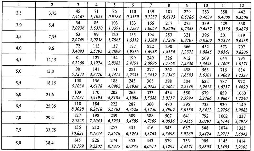


It must be borne in mind that the actual air flow rates in rectangular and round air ducts with the same cross-sectional area are not the same, even with complete equality of air flow rates. If the air temperature exceeds +20°C, then correction factors for friction and local resistance must be used.
The calculation of the ventilation system consists of the calculation of the main line and all branches connected to it. In this case, it is necessary to achieve a position so that the speed of air movement constantly increases as it approaches the suction or discharge fan. If the duct diagram does not allow for branch losses to be taken into account, and their values do not exceed 10% of the total flow, then it is allowed to use the diagram to dampen excess pressure. The coefficient of resistance to air flow of the diaphragm is calculated by the formula:

The above air duct calculations are suitable for the following types of ventilation:
- Exhaust. Used to remove exhaust air from industrial, commercial, sports and residential premises. Additionally, it may have special filters to clean the air emitted to the outside from dust or harmful chemical compounds; they can be mounted indoors or outdoors.
- Supply air. Prepared (heated or purified) air is supplied to the premises; it may have special devices to reduce noise levels, automate control, etc.
- Supply/exhaust. A complex of equipment and devices for supplying/removing air from premises for various purposes may have heat recovery units, which significantly reduces the cost of maintaining a favorable microclimate in the premises.
The movement of air flows through air ducts can be horizontal, vertical or angular. Taking into account the architectural features of the premises, their number and size, air ducts can be installed in several tiers in one room.
Calculation of pipeline cross-sectional area
Once the speed of air movement through the air ducts has been determined, taking into account the required exchange rate, the cross-section parameters of the air ducts can be calculated using the formula S = R\3600v, where S is the cross-sectional area of the air duct, R is the air flow rate in m 3 /hour, v is the speed of air movement flow, 3600 – time correction factor. The cross-sectional area allows you to determine the diameter of a round duct using the formula:
![]()
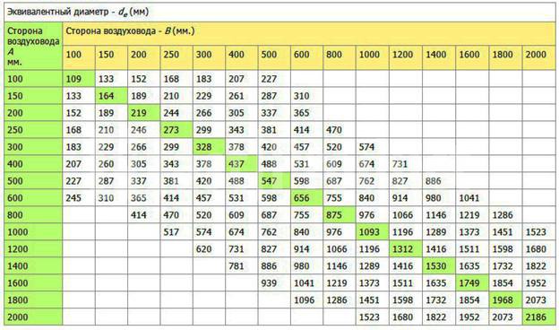
If a square-section air duct is installed in the room, then it is calculated using the formula d e = 1.30 x ((a x b) 0.625 / (a + b) 0.25).
d e – equivalent diameter for a round duct in millimeters;
a and b are the length of the sides of a square or rectangle in millimeters. To simplify calculations, use conversion table No. 1.
Table No. 1
To calculate the equivalent diameter of oval ducts, use the formula d = 1.55 S 0.625 / P 0.2
S – cross-sectional area of the oval air duct;
P – pipe perimeter.
The cross-sectional area of an oval pipe is calculated by the formula S = π×a×b/4
S – cross-sectional area of the oval air duct;
a = large diameter oval duct;
b = smaller diameter of oval duct.
Selection of oval or square air ducts based on air flow speed To facilitate the selection of the optimal parameter, the designers calculated ready-made tables. With their help, you can select the optimal dimensions of air ducts of any cross-section, depending on the air exchange rate in the premises. The frequency of exchange is selected taking into account the volume of the room and SanPin requirements.

Calculation of parameters of air ducts and natural ventilation systems In contrast to forced air supply/removal, for natural ventilation, readings of the pressure difference between the outside and the inside of the premises are important. Calculation of resistance and choice of direction must be done in such a way as to guarantee a minimum loss of flow pressure.
When calculating, existing gravitational pressures are linked with actual pressure losses in vertical and horizontal air ducts.

Classifications of initial data during calculations of air duct cross-sections During calculations, it is necessary to take into account the requirements of the current SNiP 2.04.05-91 and SNiP 41-01-2003. Calculation of ventilation systems based on the diameter of the air ducts and the equipment used should ensure:
- Standardized indicators for air purity, exchange rate and indoor microclimate indicators. The power of the installed equipment is calculated. At the same time, the level of noise and vibration cannot exceed the established limits for buildings and premises, taking into account their purpose.
- Systems must be maintainable; during scheduled maintenance work, the technological cycle of enterprise operation must not be disrupted.
- In rooms with an aggressive environment, only special air ducts and equipment are provided to prevent sparking. Hot surfaces must be additionally insulated.
Standards for design conditions for determining the cross-section of air ducts
Calculation of the air duct area should ensure:
- Proper conditions for cleanliness and temperature in the premises. For rooms with excess heat, ensure its removal, and in rooms with a lack of heat, minimize the loss of warm air. In this case, it is necessary to adhere to the economic feasibility of fulfilling these conditions.
- The speed of air movement in the premises should not impair the comfort of people staying in the premises. In this case, mandatory air purification in work areas is taken into account. In the stream of air entering the room, the speed of movement Nx is determined by the formula Nx = Kn × n. The maximum temperature of incoming air is determined by the formula tx = tn + D t1, and the minimum by the formula tcx = tn + D t2. Where: nn, tn – normalized air flow speed in m/s and air temperature in the workplace in degrees Celsius, K = 6 (transition coefficient of air speed at the outlet of the air duct and in the room), D t1, D t2 – maximum permissible deviation temperature.
- Maximum concentration of chemical compounds and suspended particles harmful to health in accordance with GOST 12.1.005-88. Additionally, you need to take into account the latest decisions of the State Supervision Authority.
- Outdoor air parameters. They are adjusted depending on the technological features of the production process, the specific purpose of the structure and buildings. Indicators of the concentration of explosive compounds and substances must meet the requirements of fire-fighting government agencies.
Installation of ventilation systems with forced air supply/removal should be done only in cases where the characteristics of natural ventilation cannot provide the required parameters for cleanliness and temperature conditions in the premises or the buildings have separate zones with a complete absence of natural air flow. For some premises, the area of air ducts is selected so that the premises are constantly maintained under pressure and the supply of outside air is excluded. This applies to pits, basements and other premises in which there is a possibility of accumulation of harmful substances. Additionally, air cooling must be present in workplaces that have thermal exposure of more than 140 W/m2.
Requirements for ventilation systems If the calculated data on ventilation systems reduces the temperature in the premises to +12°C, then simultaneous heating must be provided. Heating units of appropriate power are connected to the systems in order to bring the temperature values to those normalized by state standards. If ventilation is installed in industrial buildings or public premises where people are constantly present, then it is necessary to provide at least two supply and two exhaust permanently operating units. The size of the air duct area must provide the calculated amount of air flow. For connected or adjacent rooms, it is allowed to have two exhaust systems and one supply system or vice versa.
If the premises must be ventilated around the clock, then backup (emergency) equipment must be connected to the installed air ducts. Additional branches must be taken into account; a separate calculation of the area is made for them. A backup fan may not be installed only if:
- After the ventilation system fails, it is possible to quickly stop the work process or remove people from the room.
- The technical parameters of emergency ventilation fully meet the requirements for cleanliness and air temperature in the premises.
General requirements for air ducts Calculation of the final parameters of air ducts should provide for the possibility of:
- Installation of fire dampers in vertical or horizontal position.
- Installation of air valves on interfloor platforms. The design features of the devices must ensure compliance with regulatory requirements for emergency shutdown of individual branches of the ventilation system and prevention of the spread of smoke or fire throughout the building. In this case, the length of the section where the valves are connected should not be less than two meters.
- No more than five air ducts can be connected to each floor collector. The connection node creates additional resistance to air flow; this feature must be taken into account when calculating dimensions.
- Installation of automatic fire alarm systems. If the alarm actuator is mounted inside an air duct, then when determining its optimal diameter, the reduction in effective diameter and the appearance of additional resistance to air flow due to turbulence should be taken into account. The same requirements are put forward when installing check valves that prevent the flow of harmful chemical compounds from one production room to another.
Air ducts made of non-combustible materials must be installed for ventilation systems with suction of flammable products or with temperatures exceeding +80°C. The main transit areas of ventilation must be metal. In addition, metal air ducts are installed in attics, technical rooms, basements and crawl spaces.
The total air loss for shaped products is determined by the formula:
![]()
Where p is the specific pressure loss per square meter of the unfolded section of the air duct, ∑Ai is the total unfolded area. Within one ventilation system installation scheme, losses can be taken according to the table.
In any case, when calculating the dimensions of air ducts, you will need engineering assistance; our company’s employees have enough knowledge to resolve all technical issues.
Aerodynamic calculations of mechanical ventilation and air conditioning systems are carried out to determine the diameters or dimensions of rectangular sections of air ducts or channels, as well as to determine the pressure loss when air moves in the channel and select the appropriate fan.
One of the important factors when designing ventilation systems is the speed of air movement in the duct. At high air speeds, noise is created from friction against the walls of the air duct and turbulence at turns and bends, and the resistance of the air duct system will also increase, which leads to the need to install a fan of higher performance, and subsequently to an increase in capital and operating costs.
- 1.5...2.0 m/s - in the distribution channel with supply or exhaust ventilation grilles and deflectors;
- 4...5 m/s - for side branches of supply and exhaust ventilation ducts;
- 6 m/s - for main channels of supply and exhaust ventilation;
- 8...12 m/s - for main canals of industrial enterprises.
For the calculation, an axonometric diagram of the supply and exhaust ventilation systems is constructed. The main direction of the air ducts in the diagram is divided into sections - segments of the same length and with a constant air flow. Then the sections are numbered and all values are plotted on the diagram. The total air flow is formed by sequentially summing the air flow through the branches joining the main direction.
Calculation of the cross-sectional area of the duct
The cross-sectional area of the air duct for each section is calculated using the following formula:
where L is air flow (m³/h);
V – air flow speed (m/s);
Then calculate the preliminary diameter of the air duct in the area
D=1000∙√(4∙S/"π") mm, and rounded to the nearest standard size. The dimensions of the air ducts must be taken strictly in accordance with the values given in the reference manual.
If it is necessary to use rectangular air ducts, the dimensions of the sides are also selected according to the approximate cross-section, i.e. so that a×b ≈ S in accordance with the table of standard sizes, taking into account that the aspect ratio, as a rule, should not exceed 1:3. The minimum rectangular section is 100×150 mm, the maximum is 2000×2000.
The choice of air ducts of round or rectangular cross-section and the material from which they will be made is made in accordance with the technical conditions of the facility.
Rectangular ducts are smaller in size and can be used in rooms with limited space for ventilation ducts. Air ducts of round cross-section reduce air resistance, and, consequently, the noise of the structure, eliminate air loss and are more convenient for installation.
For your convenience, we have made this calculation for the most commonly used sizes and sections of air ducts. Address for applications for selection of equipment for ready-made projects and development of Technical Specifications for the design of air conditioning and ventilation systems: