Port cranes: a great story about powerful technology. Portal crane and its role in port operation Main types of portal cranes
Description of the gantry loading crane
The crane consists of a portal mounted on four running trolleys and a rotating part.
The portal is double-track with a 10.5 m gauge or three-track with a 15.3 m gauge.
Each trolley that is part of the crane movement mechanism has its own drive. The trolleys are equipped with hand-operated rail grips that protect the crane from being blown away by the wind when not in use.
The rotating part of the crane rests on the upper part of the portal through a slewing bearing, which includes: an articulated solar boom system, a platform, a frame, a machine cabin, and a control cabin. The rotating part contains mechanisms for lifting, turning and changing the reach, as well as devices and instruments that ensure the operation of the crane mechanisms and their control.
The boom system consists of a boom, a trunk, a guy rope and a rocker with a counterweight, hingedly connected to each other. The beam counterweight is designed to balance the boom system. The boom system ensures close to horizontal movement of the load when the reach changes.
The change in reach is carried out by a rack and pinion mechanism, the drive of which is located on the upper bracket of the frame.
The crane is rotated by a rotation mechanism installed on the platform.
A slewing bearing device made in the form of a multi-roller circle resting on a circular rail mounted on the head of the portal.
The lifting mechanism is made in the form of two single-drum winches and is designed to work with a grab and a hook suspension.
In the hook mode, operation is provided with two winches and one winch. To avoid overloading, a load limiter is installed on the crane.
To limit the lifting of the load in height, as well as to limit changes in the reach and movement of the crane, limit switches are installed.
The set of lifting devices supplied from the cranes includes a grab and a hook suspension.
The drive of all mechanisms is electric. The crane is powered by a flexible cable from ground-based speakers. The length of the cable allows the crane to move 50 m in each direction from the column. To wind the cable, a cable drum installed on the portal tightening is used.
The crane is controlled by the crane operator from the control cabin located on the turntable.
The crane kit includes spare parts and tools, the lists of which are included in the technical documentation supplied with the crane.
Design and technical characteristics of the GANZ load-lifting crane and one of its mechanisms
Basic equipment. Two electric motors are installed on the mechanisms for lifting the load and closing the grab, as well as on the mechanism for moving the crane; one each is installed on the mechanisms for turning and changing the boom reach. The electric motors are “powered” by a three-phase alternating current network with a voltage of 380 V. The control circuits of the electric motors are “powered” by an alternating current of 110 V through a step-down transformer. The electric motors of the crane's turning and moving mechanisms are flanged: the turning mechanism is vertical, the crane moving mechanism is horizontal.
The brakes of the load lifting and grab closing mechanisms have an additional hydraulic pedal drive for mechanical braking of the mechanisms when lowering the load at low speeds. The hydraulic pedal-driven swing brake has a mechanical latch. The brake pedal is interlocked with a switch that automatically turns off the electric motor of the mechanism when the brake pedal is pressed. The screw stopper on the mechanisms for turning and changing the boom reach serves to slow them down for a long time.
The electric drives of all mechanisms are controlled using magnetic controllers. In addition, to automate the control of the operation of grab winches, a differential device is installed on the cranes.
Auxiliary electrical equipment. Electric motors of all crane mechanisms, with the exception of the movement mechanism, have individual three-phase protection against short circuit currents - fuses. Electric motors of the movement mechanism, in addition to individual protection, also have general protection.
The contacts of the maximum thermal relays are connected in series to the circuits of the blocking relay coils of the corresponding electric drives. Triggering of the maximum thermal relay causes the corresponding electric drive to be turned off; the remaining electric drives of the crane remain switched on.
Limit switches are installed on the mechanisms for lifting the load and closing the grab, changing the boom extension, limiting the movement of the load-handling member and the boom extension in both directions.
The cable drum has two limit switches: one is activated by the counterweight of the drum, the other by the cable tension. In addition, two limit switches are installed on the crane travel mechanism, connected in series with the locking relay coil of the travel mechanism and breaking the power supply circuit of this relay when the rail grips are closed.
The bell whistles on the crane are turned on by the electric drive switch of the movement mechanism, and the siren is turned on by the crane operator from the control cabin. One telephone set is installed in the control cabin and on the foot of the portal.
The load limiter of the lever-spring design disables the mechanisms for lifting and closing the grab in the lifting direction when the weight of the lifted load exceeds the rated load capacity of the crane by 15%. The limiter operation limit breaks the power supply circuit of the relay coil of the zero blocking mechanisms for lifting the load and closing the grab - the load can be lowered.
On the portal there are four lamps with 60 W lamps, designed to illuminate the passages, which are powered by a step-down transformer. To illuminate the crane tracks, four headlights with 500 W lamps and two plug sockets are installed on the portal. There is a spotlight with a 100 W lamp on the boom, two headlights under the crane operator’s cabin, three lamps in the machine room, and one lamp with 60 W lamps in the control cabin. To illuminate the passages, four lamps with a 60 W lamp are placed on the rotating part of the crane.
Electric drive mechanisms for lifting and lowering loads, closing and opening the grab. For ease of control of electric drives and auxiliary electrical equipment of the crane, all direct control devices are located in the control cabin.
The power supply to the electric drives of the mechanisms is switched on by the main automatic machine in the control cabin. The control circuits for testing are turned on with a special button. The electric drives of the mechanisms for lifting loads and closing the grab are controlled using controllers that have the same asymmetrical circuits, a differential device and a pedal switch for automatic operation of the grab.
The differential device, mechanically connected to the drums of the grab winch, is designed to: automatically turn on the engine of the lifting mechanism for lifting and lowering after opening the grab in the air; softening the characteristics of the supporting motor at the end of the scooping operation.
The pedal switch is used to disconnect from the network and release the motor of the lifting mechanism during scooping for better deepening of the grab into the load.
Raising and lowering the load occurs when the handles of both controllers are set to the extreme position; this ensures the rated speed. Intermediate positions of the command controllers in the upward direction are used to move the load over short distances and obtain lower speeds, and in the lowering direction - to obtain increased speeds and single-phase braking.
To close a grab with a load, two methods are used:
· Pressing the switch pedal and then moving the handles of both command controllers to their working positions. In this case, after closing, the grab begins to automatically rise, after which the foot can be removed from the pedal.
· Move the controller handle to the working position. In this case, to lift the filled grab, it is necessary to combine the handle of the command controller with the handle of another command controller before closing it.
Crane movement mechanism. The switch for controlling the electric drive of the crane movement mechanism has a symmetrical circuit that works the same in both directions.
Device. The movement mechanism of the portal crane consists of running trolleys located under each leg of the portal. The running trolleys are connected to the legs using support devices that ensure the movement of the crane along curved paths and its rotation onto perpendicular paths, as well as the release of the trolley from under the legs of the portal for repairs. The balancing suspension of the wheels of each trolley and its articulated connection with the supporting device serve to uniformly distribute pressure on all running wheels and better overcome uneven crane tracks.
On the GANZ crane, the movement mechanism consists of four running trolleys, two of which are driven. The trolleys are three-wheeled, balanced, with a vertical hinge.
In the drive trolley, the flange motor of the elastic coupling is connected to a horizontal bevel-helical gearbox. The mechanism is braked by a double-block brake with an electro-hydraulic pusher. The motor and brake are mounted on the gearbox housing, which is mounted on the trolley frame.
Two anti-theft rail grips are located on the drive trolleys of the crane. The main elements of the gripper: spindle, limit switch for closing the control circuit, stop, spacer wedge, lever. The grippers are operated manually. When the grippers are closed, the control circuit for the electric motors of the movement mechanism is open
Maintenance. Maintenance of the crane moving mechanism occurs every shift, during maintenance-1, the components of the mechanism, rail grips and cable drum are inspected, then the mechanism is tested in action. Brakes, pin couplings, axles of running wheels and balancers, and rail grip pins are checked monthly. Once every three months, the mechanism is examined to detect damaged elements, cracks, and corrosion. Check the tightness of the threaded connections of the mechanism to the metal structure of the trolley, as well as the ring gears to the running wheels. The wear of gear teeth and open gear gears should be checked annually. During operation, the component parts of the mechanism should be lubricated in strict accordance with lubrication charts or technical documentation of the crane.
Port gantry cranes
Port portal cranes usually have a lifting capacity of 3 to 15 tf with a total dead weight of 60 to 200 tf and a weight of the heaviest mounting element of 6 to 30 tf. The lifting capacity of shipbuilding portal cranes ranges from 30 to 75 tf and higher with a total crane weight of 300-700 tf.
Portal cranes are mounted using mounting booms, portals or existing gantry cranes in the port, as well as large floating cranes. Assembly booms and portals are used primarily in cases where the port does not have portal or floating cranes with the required lifting capacity, and booms are used for the installation of single cranes, and portals are used mainly for serial installation. The assembly boom is used in an inclined version, and the crane portal moves along tracks during the assembly process. The lifting capacity of the mounting boom usually does not exceed 20, less often 30, tf, and therefore it does not allow significant enlargement of blocks.

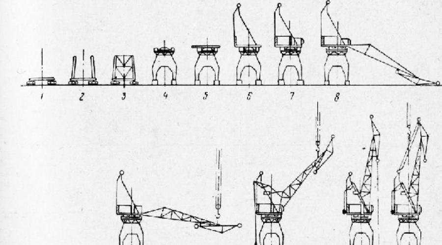
Rice. 1. Scheme of sequential operations for installing a portal crane on a turntable using the superstructure method
In Fig. Figure 1 shows a typical sequence (positions 1-12) of installing a portal crane with a slewing circle using the superstructure method, carried out using mounting tools of limited load capacity. As can be seen from the figure, here the portal is assembled from two pre-enlarged facade frames (position 2) with the subsequent installation of gratings (position 3), the upper platform of the portal (position 4) and the rotating frame (position 5). The assembly of mechanisms and frame (position 6-5) on the rotating frame is carried out at the design mark, the boom (position 8-11) is installed in an assembly with a trunk, but without a guy truss. By the time the boom is attached to the counterweight arms, the ballast of the latter
at least 50% of it has already been put in place. The issue of when to install the fixed counterweights of the rotating part (before or after installing the boom) is usually decided according to the manufacturer’s instructions, based on the condition of ensuring the stability of the crane during installation. Here, the greatest lifting height is determined by the installation condition of the draw truss (position 12), and the greatest weight is determined by the weight of the crane's turntable.
In Fig. Figure 2 shows the installation sequence of a 5-ton slewing column crane with flanged mounting joints.
Rice. 158, and reflects the assembly of one of the legs of the portal with a cross beam; rice. 2, b - installation of a leg with a cross beam on the undercarriage, temporarily strengthening them with a spacer and attaching the remaining three legs to the cross beam; rice. 2, c - installation of the annular head of the portal; rice. 2, d, installation of the lower part of the rotary column, assembled into an enlarged block with elements of the machine platform; rice. 2.5 - installation of the upper part of the column with the drive of the mechanism for changing the reach; rice. 2, e - installation of the mechanisms of the turning part, the crane operator’s cabin and the machine cabin; rice. 2, g - installation of counterweight levers, installation of the counterweight and lifting of the boom using a mounting pulley driven by a crane winch.

Rice. 2. Scheme of sequential operations for installing a portal crane on a slewing column using the superstructure method
Installation portals with a lifting capacity of up to 150 t at a height of 30-40 m allow the installation of portal cranes of all sizes in large units. In these cases (Fig. 159), both assembly and installation work are carried out under the mounting portal, and therefore the crane portal, after its assembly, is removed from under the mounting portal and inserted under it after lifting the rotating part to install the latter.
If large floating cranes are available (with a lifting capacity of 100-200 t), the portal cranes are assembled at the zero level using crawler cranes into two or three enlarged blocks, which are then installed by a floating crane. Due to the high rental costs for high-capacity floating cranes, they are brought to the site only for final lifts.

Rice. 3. Installation diagram of a portal crane with pre-enlarged blocks
In the case of using portal cranes existing in the port for installation, they tend to work with twin cranes, which makes it possible to enlarge the units to a weight of 20-30 g (with 10-15-ton cranes).
Assembly work on the portal and the rotating part can be carried out relatively independently.
The portal is usually assembled directly on the working path or section of the assembly path. In both cases, the track on which the portal is assembled must meet the tolerance standards for crane tracks, and primarily in terms of the accuracy of the track and the equal height of the rail heads under the portal bogies. Since the path may sag during installation, its marks are periodically checked by leveling.
The portal is assembled directly on its running trolleys, which are pre-positioned on the crane runway so that all right or all left flanges of the wheels of all trolleys are pressed against the rail. This position is monitored throughout the gantry assembly in order to maintain the correct track of the bogies.
Before the final connection of the portal's assembly joints, the following are checked: the track dimensions along the front and rear bogies, the equality of the diagonals of the portal at the level of the bogies and the equality of the diagonals along its edges. In addition, the upper edge of the portal (if it is assembled from several elements) is checked for flatness in the area where the turntable rests on it.
The assembly of the portal for cranes with a turntable ends with the installation of the turntable drum (if it is made in the form of a separate mounting element). When installing a drum or turntable using a thicknesser placed on the central axle, the following tolerances are checked: concentricity of the axle to the lantern ring, fluctuations in the height of the lantern flanges; the correctness of the circumference of a circular rail - only for a conical rail; flatness of the rail. In addition, the pitch of the lanterns at the drum joints is checked using a caliper.

Rice. 4. To check the assembly of the crane turntable drum
For cranes on a slewing circle, after installing the slewing part assembly or the slewing part platform on the portal, the slewing bearing and the engagement of the ring with the sprocket are checked. To do this, the platform is slowly turned, observing the turning resistance, the engagement conditions (lateral clearance) of the sprocket and lantern ring, as well as the contact conditions of the support wheels with the rail or the rollers with the upper tires.
Once the assembly is complete, the lower part of the column is inserted into the crane portal on the rotary column and the following adjustments are made to the slewing bearing. First, the position of the supporting horizontal wheels relative to the annular rail is adjusted in order to obtain the smallest gap between them and the rail. At the same time, if possible, the operation of the engagement of the crown pair is also checked, since the lateral clearance in the engagement is associated with the installation of the wheels.

Rice. 5. Schemes for checking the assembly of support bases (on the portal) of the crane slewing column
When assembling the frames of the rotating part of cranes with articulated booms, the actual positions and relative distortions of the holes for the hinges of the kinematic system of the jib are monitored.
A special place in the installation of portal cranes is occupied by the installation of jib booms, and first of all jib jib of the articulated type. The basic installation diagram for such jib booms is the diagram shown in Fig. 6, a. Here the jib assembly with spacers between its links is installed on the crane in the position of minimum reach, which allows you to keep the counterweight of the boom also in the position of minimum reach. In this case, a significant lifting height of the mounting means is required, ensuring that the jib is suspended above its center of gravity.

Rice. 6. Installation diagrams for articulated booms
If the lifting height of the mounting equipment is limited, the boom can be installed in the position of maximum reach (Fig. 6, b), but then the counterweight lever must also be first raised to the position of maximum reach, which often presents certain difficulties. The boom can also be installed on a crane with a reach exceeding the maximum working one (Fig. 6, c), which requires an even lower lifting height and allows you to maintain the counterweight in the position of minimum reach, but necessitates the use of a special pulley block P to bring the boom to the position of minimum reach .
In cases where the lifting capacity of the mounting devices is insufficient to lift the jib in full assembly, the draw truss can be lifted separately, and sometimes (especially heavy jib booms) the boom is lifted in three steps (the root part, the top with the trunk and the draw truss). Installing the trunk on the boom at the design mark, due to the difficulty of this operation, is avoided.
Lifting the boom by the end of the trunk, used when the lifting height of the mounting tools is insufficient, is not recommended, as this often leads to accidents caused by twisting of the booms.
Installation movements of portal cranes between parallel tracks are usually carried out along a temporary perpendicular path, for which the portal trolleys are rotated 90°.
Movements between non-parallel tracks, as well as rotations of the portal relative to the vertical axis, are carried out due to the movement of the crane along curves.

Rice. 7. Scheme of fitting a four-wheeled crane trolley into a curved rail of an installation path

Rice. 8. Scheme of fitting the crane portal on the transition section of the curved installation path

Rice. 9. Portal crane: 1 - legs, 2 - running trolleys, 3 - rotating frame, 4 - upper portal assembly, 5 - boom, 6 - cabin, 7 - guy, 8 - frame, 9 - counterweight, 10 - fixed counterweight, 11 - control station (cabin)
A gantry crane is a universal intermittent reloading machine, usually having an electric drive powered by onshore power. The portal crane got its name because its base is made in the form of a letter. The main elements of the portal are legs resting on running trolleys, connected at the top by a span. The wheels of the trolleys rest on the crane tracks along which the crane moves. The dimensions of the portal are selected in such a way that trains can pass between its legs. Depending on the number of railway tracks laid under the portal, portals are distinguished as single-track, double-track and triple-track.
Sometimes the portal is replaced with a half-portal, which has only two legs. The span is supported through a pair of running trolleys on a rail laid on the wall of the warehouse. The rollers or rollers of the rotating frame with the frame attached to it rotate around a vertical axis (baller) installed on the portal. This axis prevents the possibility of radial shift of the rotating part of the crane. The control panel is located on the boom side; on the opposite side a fixed counterweight is attached to the frame.
The portal crane has the following movements: lifting (lowering) the load, changing the boom reach, turning around the stock, moving the portal along the crane tracks.
In accordance with this, the portal crane has a lifting mechanism, a mechanism for changing the boom reach, a swing mechanism and a movement mechanism. The lifting mechanism (the main mechanism of the crane) is also called a lifting winch and consists of an electric motor, a gearbox, a cargo drum on which the cargo rope is wound, and a braking device. If there is only one drum, the winch is called single-drum. Double-drum winches, which can rotate simultaneously or separately, are widely used, allowing the crane operator to control a grab or other attachment to grab a load.
The rotating mechanism and the mechanism for changing the boom reach are also located on the rotating part of the crane. Travel mechanisms are usually installed in running trolleys.
When the reach changes, the boom moves along a certain radius, while the load moves only horizontally. This is achieved by using various special devices. On the tap shown in Fig. 9, such a device is a jib hinged at the end of the boom and a flexible guy.
The main parameters of cranes are lifting capacity, maximum boom radius, operating speeds.
The lifting capacity of the cranes is standardized. In massive reloading operations, there are portal cranes with a lifting capacity of 5, 10, 15 T. Cranes with a lifting capacity of 5 T are used mainly for reloading main cargo. To reload heavy weights, equipment, and bulk cargo, cranes with a lifting capacity of 10 and 15 tons are used.
The boom radius is measured from the crane's turning axis, usually its maximum value is 25-30 m.
Its performance depends on the operating speeds of the crane, however, design considerations force us to limit them to the following limits: load lifting speed 45-80 m/min, swing speed 1.5-2 rpm, speed of boom radius change 50-60 m/min, portal moving speed 20-30 m/min.
Cranes with lower lifting capacities have higher speeds.
TO Category: - Port lifting and transport machines
A gantry crane is a loading equipment that has a large lifting capacity. A massive rotating structure is installed on a portal that moves on rails. This technique is used in open areas because it is heavy and large in size. Depending on the design, portal cranes have different applications.
Using gantry cranes
Maskus is a portal for the sale of equipment, where you can find various equipment for warehouse work. The catalog presents various container handling equipment and other warehouse machines that allow you to increase work efficiency. New and used warehouse forklifts, stackers and pickers without any operating time and used can be purchased and sold using our portal.
Features of port gantry cranes
Mobile harbor cranes are used for containers and other heavy cargo. Among their features:
- load capacity - 1.5-2 tons;
- reach - 15-40 m;
- availability of replacement equipment.
As a rule, machines with a lifting capacity exceeding 3 tons are equipped with hooks for piece cargo and grabs. Grabs are used to a limited extent; most lifts are equipped only with a hook. The load capacity usually remains constant at all flight ranges.
Among modern mobile cranes, the most popular are universal models that are suitable for any port work. They are highly efficient and productive, handling heavy loads quickly and efficiently.
Purchase and sale of special equipment
Port cranes are complex and expensive equipment that you cannot do without when working in a port. You will find different types of such equipment on the Mascus portal, where both new and used forklifts are available. Offers from individuals and companies will help you find exactly the option that suits you.
You can select equipment by manufacturer, cost, location and other parameters. A special filter will help you navigate the wide range. Delivery from other countries and throughout Russia is carried out by transport partner companies. Choose profitable offers on the purchase and sale of special equipment on the Maskus portal!
Portal jib cranes
Portal jib cranes are the most common type of concrete paving crane used in hydraulic engineering to supply buckets of concrete mixture from the overpass to the building blocks. Being installed in the main mechanization area, these cranes serve all preparatory work of the concrete complex, and are also used in open areas to service large-scale assembly and reloading work.
A portal jib crane is a supporting structure - a portal moving along rail tracks with a rotating crane part installed on it. The portal is the main difference between portal-jib cranes and jib cranes of other designs. The rotating crane part is unified for installation on various mobile support structures (Fig. 31). The crane portal can cover several railway tracks (one-, two-, three- and multi-track portals).
The lifting capacity of construction-type portal jib cranes reaches 20/30 g at an outreach of 50/20 m, which ensures the supply of concrete mixture in buckets with a capacity of 6 m3.
The depth of lowering the hook below the head of the crane rail depends on the height of the concrete trestle and reaches 70 m or more; the lifting height of the hook above the crane rail is 36 m.
Portal jib cranes of the construction type are made only of hook type. Their portals have a large height, since reinforcement trusses and other large-sized cargo for construction purposes can be transported under them along the overpass.
Construction cranes have the same high lifting speeds as loading cranes. However, their turning speeds and changes in reach are somewhat lower than those of reloading ones, which is necessary to reduce the swinging of the load, which usually hangs on long ropes.
The lifting capacity of special type portal jib cranes reaches 100 tons and reach up to 50 m.
A general view of the construction portal-jib crane is shown in Fig. 32. The main components of the crane are: boom, frame, rotating frame, slewing device, portal, mechanisms for rotating the rotating part, lifting the load and changing the reach, crane control cabin.
The movement of the crane is carried out by electric motors located on the portal's drive trolleys, from where rotation is transmitted to the wheels through a gearbox. An individual drive is easy to operate and repair and is not so sensitive to damage to the portal.

Rice. 31. Diagrams of portal jib cranes:
a - portal; b - semi-portal; c - on a triangular stand (sloping); g - moving along the portal; d - grab with hopper; 1 - loading hopper; 2 - conveyors; 3 - sleeves
Considering that these cranes in hydraulic engineering conditions are usually installed on high concrete trestles, and also keeping in mind the large windward area of the crane and load, the number of drive wheels of the crane is normally taken to be 50%, and sometimes 100% of their total presence, which eliminates the risk of slipping.
In Fig. 33 shows typical running trolleys of portal jib cranes with a lifting capacity of 3-25 tons manufactured at the plant named after. Kirov. The gantry leg of the three-ton crane rests directly on the trolley; for five-ton cranes, the pressure of the portal leg is transferred to the same trolley and additionally to the third wheel; for 10- and 15-ton cranes, the gantry leg rests through a balancer on the drive and idle trolleys.

Rice. 32. Construction portal-jib crane: o - with a curved trunk and a flexible guy; b - with a straight trunk and a rigid guy

Rice. 33. Types of trolleys for portal jib cranes: a - two-wheeled; b and d - three-wheeled; c - four-wheeled; g - eight-wheeled
To ensure the correct movement of the portal along the paths, the following must be observed:
a) single-line installation of the stripes on each side of the portal and parallelism of the lines of the wheels of both sides of the portal;
b) equality of diameters of all driving wheels;
c) correct wheel profile. Failure to comply with these conditions leads to a violation of the geometry of the crane portal and to premature wear of its movement mechanism.
Portal jib cranes are distinguished mainly by the structure of the booms, which are the most characteristic elements that determine both the design of the cranes and their performance qualities.
Boom devices, as a rule, have horizontal movement of the load and are made with straight or articulated booms of various types.
Articulated booms with a balanced mechanism for changing the reach ensure a horizontal trajectory of movement of the load suspended on the hook, which simultaneously creates conditions for the balance of the load relative to the mechanism itself.
The most common are articulated booms with horizontal movement of the end blocks, made according to one of the following schemes: a) a boom with a flexible jib guy (see Fig. 32, a) and b) a boom with a rigid jib guy (see Fig. 32.6 ).
The supports of the booms are the lower hinges, which connect the booms to the rotating frame, and the boom rods, which connect the booms with the mechanisms for changing the reach and the counterweights that balance them.
For inspection and maintenance of the jib end blocks, the booms are equipped with a ladder with railings and a platform.
The crane booms are balanced by movable counterweights, which are selected so that the moment created by their weight relative to the axis of rotation of the lever, for all positions of the booms, is equal to the moment on the same axis created by the total weight of the booms (boom, jib and guy). With this arrangement, the arrows are always in a state of indifferent equilibrium, and little effort is required to change their reach.
Since when the angle of inclination (extension) of the articulated booms changes, the load moves almost horizontally, when performing this operation, additional energy is not spent on lifting the load.
The use of articulated and balanced booms makes it possible to easily and safely change the reach of a crane with a load, using this movement as the main working movement, along with the lifting and turning movements.
Mechanisms for changing the reach usually have a rigid kinematic connection with the boom device in order to exclude spontaneous movements of the booms under the influence of horizontal forces (wind, inertia forces, deviation of cargo ropes from the vertical, etc.).

Rice. 34. Types of reach change mechanisms
In Fig. 34 shows the main types of mechanisms for changing reach: rack and pinion (a) with gear or pinion racks, screw (b) with a rotating nut or screw, hydraulic (c), sector (d), sector-crank (e) and crank-rod (e), in which the stepper is connected directly to the boom or to the rocker. The rack and pinion mechanism is the simplest of all types, easy to manufacture and is increasingly used.
The rotating part of the crane (Fig. 35) rests on a slewing device in the form of wheel, roller or ball bearings with a centering pin (column) fixed in the metal structure of the portal. The frame of the turning part is equipped with lifting winches, rotation and change mechanisms: take-off, electrical equipment and a cabin with a control panel.
The mechanisms for turning the portal-jib cranes consist of a slewing support device that supports and centers the slewing part of the crane, and a drive that rotates the slewing part.

Rice. 35. The rotating part of the portal-jib crane on the turntable:
1 - lever with a boom counterweight; 2 - rack and pinion mechanism for changing the reach; 3 - winch; 4 - rotation mechanism
Depending on the type of slewing support, a distinction is made between cranes with a device mounted on turntables (wheeled, roller and ball valves) and those installed on slewing columns. Turning mechanisms usually have torque limiting clutches and open controlled brakes. Recently, hydraulic drives have also been used.
The lifting mechanisms of jib cranes are very diverse. The main parts of the lifting mechanism are load-handling devices, rope pulleys, a drive winch, a control system and signaling and safety devices. The layout and design of lifting devices, winches and other components, as well as the rope reeving scheme depend on the lifting capacity, purpose of the crane and the type of its boom device.
All portal jib cranes are equipped with load limiters and boom outreach indicators.
Portal-jib full-rotating self-propelled cranes are most widely used when laying concrete mixtures from concrete trestles into the middle and high parts of structures. These cranes are especially important when combining construction and installation work during the construction of hydraulic structures, where, along with laying concrete, a large amount of work is carried out on the installation of metal structures of the switchboard compartment and embedded parts of hydraulic units. With the correct location of the cranes in relation to the switchboard compartment and suction pipes, it seems possible to service the entire area of laying the concrete mixture and installation work on the hydroelectric power station building.
Installation of the crane must be carried out under the guidance of an experienced specialist according to a pre-drawn up project for organizing installation work. The installation method depends primarily on the available installation equipment, their load capacity and lifting height.
When operating portal jib cranes, the main attention should be paid to the condition of the rail tracks, compliance with established rules for lifting loads, ensuring the stability of the crane when not in operation and compliance with safety regulations. When operating cranes, a system of scheduled preventive and current repairs, regular inspection of cranes, adjustment and lubrication of individual components and parts in accordance with factory instructions, and systematic monitoring of the condition of the supporting structure of the crane and its mechanisms are mandatory.
The stability of a portal-jib crane lifting (or lowering) the maximum load is checked taking into account the influence of inertial forces and wind pressure directed towards the load with the calculated pressure for the operating state of the crane.
For a crane without a load, the stability check is carried out taking into account the effect of wind with the calculated pressure for the crane's non-operating state.
TO category: - Masts, chevres, portals and mast-jib cranes

A portal crane is a type of crane equipment that is located on a portal. Such a crane moves along special rail equipment, which is located on an overpass or on the road surface. Currently, RHC portal cranes are very popular due to their high quality and affordable price.
All portal cranes can be divided into the following types:
Pavements;
Port;
Pneumatic cranes;
Rail mounted cranes;
Conveyor systems;
Dock;
Barge crane;
Beam cranes.
Overhead cranes
An overhead crane is a quay crane, which is characterized by a bridge-type span structure. The number of bridge consoles and design will depend on the berth layout and the purpose of the crane. The crane itself consists of a suspended cargo trolley, a metal structure, a movement mechanism, an automatic gripper, a power supply cable, a cable drum, guy ropes, a gripper for long lengths, a grab and a vertical stand. The load-bearing elements of the crane structure, like the trolleys, are made of low-alloy steel. To resist fatigue and improve manufacturability, each portal frame is made from welded box-section beams. There are also locking devices on the crane to ensure safety.
Port cranes
The carrying capacity of such devices ranges from 1.5-20 tons. If the lifting capacity is more than 3 tons, then they are equipped with replaceable equipment: hooks for piece cargo and grabs for bulk cargo. Depending on the vessels being serviced and the width of the border warehouses at the port cranes, the maximum reach is 15-40 m. The gauge of the portal will depend on the number of railway tracks that the portal covers.
Rail mounted cranes
This type of crane (RMG) is a container gantry crane. The crane runs on rails, is equipped with a spreader and can lift and stack 20-40 containers. RMG cranes are designed for container handling work. Such cranes are distinguished by the fact that they have an electric drive, high speed and high lifting capacity. They are very efficient for transferring large quantities of containers onto rails from the road. The use of such devices makes it possible to more efficiently use the entire terminal area.
Pneumatic cranes
Such devices are used for work in warehouses and are distinguished by their performance. They are equipped with components in accordance with customer needs. The basis for the reliability of such cranes is:
Complete absence of hydraulics;
Use of AC motors;
Electric drive with frequency regulation.
The above components help reduce maintenance work.
Dock cranes
Such cranes form a special group. They are designed for work inside docks and are installed on the sides of floating docks. The stability of the structure is ensured by counterweights, and if necessary, concrete is poured into the portal supports. Dock cranes are designed taking into account dock trim and roll.
Conveyor systems
Such systems provide the ability to transport almost any bulk cargo. They are characterized by increased productivity, and transportation is carried out at an angle of inclination from 0 to 45 degrees, if one drive is running. If 2 drives are running, then the angle is unlimited.
Beam cranes
Such designs are bridge-type crane equipment, which is used to perform lifting, transport, unloading and loading operations in industrial workshops, on crane trestles and warehouses of manufacturing enterprises. Such special equipment is used in the process of unloading river and sea vessels, construction of industrial and civil structures.