Connecting and installing electrical wiring in the garage. Wiring your garage is easy. We connect a single-phase meter
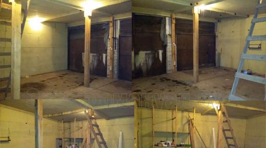
If you want to learn how to conduct electrical wiring in a garage, then in this article we will try to understand this issue using the example of a garage box. Initially, the garage was connected with a PVS-3 x 2.5 wire at 220 V. The garage was connected to two sockets and six 60 W incandescent lamps. At the entrance there were two 16 A machines, one for sockets and the other for lighting. The total area of the box is 64 m2 8 by 8 meters (Fig. 1).

Rice. 1. Garage before installation of electrical wiring.
Electrical wiring in the garage
The first thing we need is a wiring diagram for the garage. You can draw the diagram yourself or use a ready-made one (Figure 2), simply modifying it to suit your needs. Before starting installation work, it is necessary to determine some points.
- What voltage should be supplied to the garage: 220 V or 380 V?
- What cable should I use to connect electricity to the garage?
- Which cable will go to the sockets and which to the lighting?
- What sockets should I install?
- What kind of lighting lamps should I use?
- What machines to install and is it necessary to install an RCD?
- Which meter should I install if I pay for electricity by meter?
- Count the number of cables, cable ducts, corrugated pipes.
If the garage will be used as a warehouse, for storing personal belongings, boats, etc., then a voltage of 220 V will be sufficient. But if you are going to do welding work, connect a compressor, a car wash or other powerful equipment, then it is better to supply a three-phase power supply of 380 V.

Rice. 2. Conduct electrical wiring in the garage - diagram.
- L1 - 10 W LED floodlight with motion sensor. (installed above the entrance to the garage, convenient in the evening when it gets dark, Fig. 4.)
- L2 - 6 W LED lighting lamp with motion sensor. (installed inside the garage, lights up when entering the garage.)
- SV - ventilation system. (connected separately, switched on if necessary.)
In our case, it was decided to supply 380 V to three phases. The cable for connecting from the switchboard to the garage was VVG 4 x 4.0. We laid 35 m in corrugation. For sockets we used VVG cable 3 x 2.5, for lighting - ShVVP 2 x 0.75. LED lighting lamps. Automatic machines and ouzo IEK. Three-phase meter.
Additionally, below is a visual diagram of the garage wiring (Fig. 8).

Rice. 8. Visual diagram of the electrical wiring in the box.
Conduct electrical wiring in the garage - preparation
So, we have a schematic diagram for connecting sockets and lighting. You can mark the places for installing lamps and sockets according to the location in the box and calculate the amount of cable that we will need. We also count the cable channel and corrugation (if necessary).

Rice. 3. Garage equipment.
Now let's figure out how many machines and RCDs we will install and of what denomination. We divide all electrical installation products into groups.
- L1 - two triple 16 A sockets and two double 16 A sockets.
- L2 - two triple 16 A sockets and one double 16 A.
- L3 - lighting and ventilation.
- L1, L2, L3 - one three-phase 32 A socket.
For lighting, five LED luminaires 595 x 595 x 19 36 W 3000 Lumens 6500 K ceiling overhead and seven LED waterproof luminaires SSP-456 2 x 18 W LED-T8/G13 IP65 ASD were selected (Fig. 3). Also two 100 W floodlights with separate switches. For exhaust duct fan VK 250B power 110 W.
So, the total power of lamps and ventilation is:
- 5 pieces. x 36 W = 180 W.
- 7 pcs. x 36 W = 252 W
- 2 pcs. x 100 W = 200 W
- 180 + 252 + 200 + 110 = 742 W.
- Where I is current A;
- P - device power (usually indicated in the product characteristics);
- U - mains voltage 220 V.
742 ÷ 220 = 3.37 A.
- We add 20% (as when calculating electrical networks for industrial production).
- In total we get 4.1 A.
All the parameters have been received, we look at what happened, and we go to the store to do some shopping.
- Input machine IEK 3p C/ 32 A VA 47-29 — 1 pc. ≈ 340 rub.
- Input RCD IEK VD1-63 4P 40 A 30 mA - 1 pc. ≈ 1750 rub.
- Group L1, L2 - automatic machine IEK 1p C/ 16 A VA 47-29 - 2 pcs. ≈ 90 rub/piece.
- Group L3 - automatic machine IEK 1p C/ 6 A VA 47-29 - 2 pcs. ≈ 90 rub/piece.
- Group L1, L2 - RCD IEK VD1-63 2P 25 A 30 mA - 2 pcs. ≈ 890 RUR/pcs.
- Three-phase electricity meter TAYPIT NEVA 303 1S0 - 1 pc. ≈ 2400 rub.
- Lamp 595 x 595 x 19 36 W 3000 Lm 6500 K ceiling - 5 pcs. ≈ 800 rub/piece.
- Lamp SSP-456 2 x 18 W LED-T8/G13 IP65 ASD - 7 pcs. ≈ 740 rub/pcs.
- Socket SCHNEIDER ELECTRIC BLNRA010311 - 4 pcs. ≈ 230 rub/piece.
- Socket SCHNEIDER ELECTRIC BLNRA010211 - 3 pcs. ≈ 190 rub/piece.
- LED lamp ASD LED 18 W 230 V G13 6500 K - 14 pcs. ≈ 170 rub/piece.
- Cable VVG 4 x 4.0 - 35 m ≈ 125 rub/m.
- Cable VVG 3 x 2.5 - 50 m ≈ 60 rub/m.
- ShVVP cable 2 x 0.75 - 50 m ≈ 14 RUR/m.
- Cable channel TDM SQ0402-0006 25 x 25 - 2 m ≈ 70 rub/m.
- Cable channel ELEKOR 10 x 7 - 8 m ≈ 24 RUR/m.
- Cable channel ELEKOR 20 x 10 - 38 m ≈ 35 rub/m.
- Duct fan VK 250B 110 W. - 1 PC. ≈ 5800 rub.
- Consumables (ties, self-tapping screws, electrical tape, self-clamping clips) ≈ 1000 rub.
- Electrical panel - 2 pcs. ≈ 800 rub.
As a result, to do the installation of electrical wiring in the garage with our own hands, we will need approximately 37,000 rubles. for equipment + 3000 rub. local electrician for connection to the switchboard and 3-5 days of free time.
Carry out electrical wiring in the garage - installation
So, for now, the preparation is complete. The markings for lamps and sockets have been made (we did this when we were figuring out what to install, where, and counting how much cable duct was required), we can begin installation.

Rice. 4, 5, 6. Electrical wiring in the garage - installation.
- The first day., lamps in pre-marked places (I won’t describe how to do this, almost anyone can handle it). Next, we cut the cable channel and fasten it along the walls to the electrical installation products.
A little advice. When cutting and attaching cable channels, mark the cover and base, for example, 1-1, 2-2, and so on, so that you don’t have to look for which cover is from which cable channel.
Attention!!! We do not connect the input cable to the panel until the electrical installation work is completed and checked. All work is carried out on de-energized electrical equipment!
- Second day. We assemble and install the electrical panel (the circuit breakers are mounted in the panel on a DIN rail, so there will be no difficulties with this, Fig. 5). Next, we begin to stretch the cable from the sockets and lamps to the panel. We leave a cable reserve of approximately 10-15 cm near the sockets, and 20-30 cm near the electrical panel and lamps (in general, you can estimate the location in Fig. 6). Don’t forget to mark the cable near the panel, for example, ventilation, lamps, 1 group of sockets, etc. Otherwise, then you will have to call which cable is laid where. In our case, one room and few groups, even if you forgot about the markings, you can fix it in 10 minutes. But if we are talking about several rooms and the number of groups goes into dozens, then you can kill several days.
A little advice. When laying the cable, so that it does not fall out of the cable channel, buy steel spring wire ∅ 0.5-1 mm. and cut it 1-2 mm longer than the base. You can temporarily secure the cable with wire by inserting it into the spacer between the inner walls of the cable channel.
- Day three. We're going to the garage. We connect sockets and lamps, stripping and adjusting the cable in place. Those who don’t know how to do this can read the article. Next, we have a schematic diagram of the electrical wiring in the garage; we connect all the wires according to our diagram. We are not in a hurry to connect the input cable. We take a screwdriver and check again that each wire is well screwed in (you can tug on the cable to make sure it doesn’t fall out). Next, we check what we did for a short circuit. To do this, you can use a multimeter. Now that we are convinced that everything was done correctly, we connect the input cable to the machine and call a local electrician, have him turn on the switch. After the call, we take an indicator screwdriver or a multimeter and check whether we have three phases; if so, then turn on the input machine, while the other machines are turned off. Three LEDs on the meter will light up, turn on all groups one by one. Let there be light!!! (Fig. 7)

Rice. 7. After installing electrical wiring in the garage
Electrical wiring in the garage at 220 V

Rice. 9. Electrical wiring diagram in the garage 220 V
A few more words about wiring for 220 V. In general, the principle of wiring does not change. The same cable, cable channels, light bulbs, sockets. We only change the counter and machines, and not everything. Accordingly, we exclude the 380 V outlet as well. The wiring diagram for a 220 V garage is shown above (Fig. 9). We change the input circuit breaker to IEK 2P 25 A, meter 220 V. We leave everything else the same as in the description for the 380 V wiring.
Conclusion
We hope you find our article on “Wiring Electrical in a Garage” helpful. In the article, we tried to explain in an accessible way how to make electrical wiring in a garage with your own hands and what electrical equipment can be installed.
Energy supply is one of the important stages of work on arranging a house for a car. The wiring here, as well as installation technologies and methods of organizing it, differ from the implementation of electricity supply to other premises.
Without electricity, the arrangement of a garage is not complete, since it often serves not only as a place to store a car, but also for repairs or other work related to the use of electrical equipment and power tools.
Rules and basic requirements
Existing garage electrical regulations are aimed at ensuring fire safety, explosion hazards and reducing the likelihood of a person being exposed to dangerous electrical current.
Among the basic rules and requirements for garage power supply and wiring are:
- electricity received from the supplier must be accounted for, that is, pass through a legal metering element - a meter;
- electrical wiring inside the garage must be correctly implemented in two ways: open (in corrugation) and closed (in grooves);
- according to the PUE (electrical installation rules), in rooms with an aggressive environment that have the possibility of ignition, explosion of fuel, fuels and lubricants, circuit breakers must be installed that limit the current, protecting the wiring from overheating in the event of a short circuit;
- separation of power and lighting networks is carried out with the possibility of implementing duty (emergency lighting);
- for carrying, basement lighting (inspection pits) and extension cords, a reduced voltage with galvanic isolation of less than 42 volts is used, most often it is adapted for common lamps with a rated voltage of 36 or 12 volts;
- wiring must be designed for current, which directly depends on the power of the electrical equipment and the tool used.
Having familiarized yourself with these rules and requirements, it becomes clear that it is possible to do the wiring yourself; for this you will only need a standard set of electrical installation tools and cable products.
Garage wiring diagram
When drawing up an electrical wiring diagram in a garage, you need to take into account the construction features of this room, but the main positions must remain unchanged. All power supply must be supplied through one common input circuit breaker, taking into account the loads of all outgoing lines.
An electric meter is installed on each of the lines or after the input machine, which is sealed by services monitoring the illegal use and theft of electricity. If this is a garage cooperative, then its administration monitors the voltage received by the consumer.
In order to protect a person from falling under an electrical potential dangerous to his life and health, a sensitive and fast-acting RCD device (residual current device) is used.
When developing an electrical circuit for a garage, it is necessary to consider the possibility of connecting not a single-phase, but a three-phase circuit, since it is this circuit that is used for the normal operation of asynchronous electric motors that are equipped with machines used in everyday life (sharpening, drilling, etc.). With a three-phase option, the power of this electrical equipment will not be reduced, and this is important for organizing a workplace in the garage. The development of wiring and electrical circuits can be carried out both before and after connecting the electricity.
There are two main electrical wiring diagrams:
- For a garage without an inspection hole.
- For a room with an inspection hole and a cellar. When developing a power supply circuit, in this case a step-down transformer is required to power the lamps in the inspection pit and cellar, since these rooms have high humidity. The housing of the luminaires must have a sealed design with rubber seals on the cover and at the wire entry point.
Important! If you plan to install a refrigerator or other equipment in the garage without a built-in voltage stabilizer, and the electrical circuit is unreliable, that is, there is a possibility of an increase or decrease in the minimum voltage, then it is recommended to install a device that normalizes it - a stabilizer.
Preparation for work
The preparatory procedure includes the selection of the necessary materials and tools that will be needed to carry out installation work on laying, fastening and connecting electrical wiring in the garage.
List of tools:
- flat and Phillips screwdrivers of different sizes;
- pliers;
- round nose pliers for making accurate connections to machines;
- hammer drill, grinder for grooves, holes for sockets, as well as installation of mounting brackets for cable fastening;
- voltage indicator to check the absence of potential and safe operation, since even with the input circuit breaker turned off, one cannot be absolutely sure that there is no voltage in a separate section of the circuit (the current-carrying elements of the circuit breaker are hidden in the housing, so the installer cannot verify the reliability of the connection of its contacts, that is no visible circuit break);
- hammer, chisel;
- insulating materials (insulating tape, PVC pipe, etc.).

List of materials needed to organize electrical supply to the garage:
- current-limiting and protective devices for supplying voltage and its control (circuit breakers, RCDs, stabilizers);
- electric meter with electrical panel;
- cable products (wires);
- distribution boxes;
- lighting switches;
- sockets
After acquiring all the necessary materials and tools, you can begin preparatory work and directly laying the wiring in the garage with your own hands.
Step-by-step instructions for installing wiring in a garage:
- The preparatory stage - all construction work on cutting grooves, marking, punching holes in the walls for cables, places for installing sockets and switches. The depth of the groove is selected individually and will depend on the thickness of the cable or insulated wire being laid. Electrical wiring must run strictly vertically or horizontally along the walls, and any turn must be made at a right angle. This rule applies to both external and internal types of installation of cable products. If there is any type of heating in the room, the wire must not be located closer than 10 cm from the heating pipes. It is recommended that specialists increase this distance to 25 cm. The hole for sockets is made at a distance of 0.6 m from the floor, and switches - at a height of 1.5 m at a distance from the door frame of no less than 10-15 cm. Unlike apartments and residential premises, in garages, light switches are most often installed near the entrance gates or doors.
- Installation of electrical panel. The body of the electrical panel must be made of dielectric material, the dimensions of which depend on the dimensions of all the machines installed in it, the electric meter, the RCD, and the step-down transformer for lighting the pit. In some cases, the electrical panel is divided into two parts: a switchboard with an automatic input device, an electric meter and a unit with automatic power supply units for separate groups of consumers (lighting, sockets, etc.) with the possibility of installing a step-down transformer 220/36 or 12 Volts. After installing the electricity metering element, it is sealed.

- Laying the external part of the electrical wiring. If the garage is built separately, then the external part of the wiring is done by air, calculating the cross-section of the cable, its length from the nearest power distribution point. In the case of implementing the energy supply to a garage in a cooperative, this part of the work is undertaken by the administration, laying the input cable along the walls of the garages, and is subsequently responsible for their safety and technical condition. Basic requirements for an overhead cable line: height above the roadway - at least 6 m, above the pedestrian area - 3.74, and entry into the premises at a height of at least 2.75 m.
- Internal wiring in the garage. The type of organization of internal registration depends on the type of power supply: single-phase or three-phase. Of course, three-phase voltage is more functional, as it makes it possible to connect not only household appliances, but also professional equipment designed for such voltage. The transition of electrical equipment to single-phase reduces the power of this equipment. All internal wiring is carried out hidden (using grooves) or externally (in a metal corrugation). The cross-section of the conductor is selected based on the load used according to the table below.
| Conductor cross-section, mm2 | Copper conductors of wires and cables | |||
|---|---|---|---|---|
| Voltage 220 V | Voltage 380 V | |||
| Current strength, A | power, kWt | Current strength, A | power, kWt | |
| 1,5 | 19 | 4,1 | 16 | 10,5 |
| 2,5 | 27 | 5,9 | 25 | 16,5 |
| 4,0 | 38 | 8,3 | 30 | 19,8 |
| 6,0 | 46 | 10,1 | 40 | 26,4 |
| 10 | 70 | 15,4 | 50 | 33,0 |
| 16 | 85 | 18,7 | 75 | 49,5 |
| 25 | 115 | 25,3 | 90 | 59,4 |
| 35 | 135 | 29,7 | 115 | 75,9 |
| 50 | 175 | 38,5 | 145 | 95,7 |
| 70 | 215 | 47,3 | 180 | 118,8 |
- Lighting of the inspection pit. These circuits are powered by a transformer that reduces the voltage to a value safe for humans below 42 volts. It is recommended to use LED-based lamps as light sources due to their efficiency and economy, as well as a long service life.
Important! The light switch necessarily interrupts the phase wire, and not the working zero wire.
- Wiring of the socket network. The main requirements are reliable insulation of the connection points and correct calculation of the cable cross-section in accordance with the load current. When using a voltage of 220 volts, it is performed with a two-core cable when using an RCD and a three-wire cable when organizing power supply to sockets with a ground loop.
- Proper organization of grounding. Grounding has the main function of protecting a person from electric shock in the event of breakdown of equipment insulation and the appearance of danger on the conductive circuit. The implementation of a separate grounding loop in cooperative garages is problematic, in contrast to car spaces located near a private house. The ground loop is made by driving metal rods into the ground in the shape of a triangle, then connecting them to each other. A 40*1.5 mm metal strip is used as a grounding bus, which is laid directly into the garage, where it is connected to the grounding conductor.
Important! The ground loop is never used as a working zero in single-phase circuits.
Safety Key Points
- Safety rules should not be neglected, since the life and health of the person installing and implementing the garage’s energy supply with their own hands depends on it.
- All work on live parts is carried out after disconnecting it from the electrical network and checking for the presence of dangerous potential. Use only serviceable and tested voltage indicators.
- Before working with a hammer drill, angle grinder, or other electric tool, you should visually check the power cord for damage to the insulation.
- Wear safety glasses when working with power tools.
Thus, connecting electricity, distributing cable products, as well as organizing a workplace and lighting in the garage is a simple procedure if you comply with electrical safety requirements and also listen to the advice of professionals on choosing the cross-section of wires, switching and protective equipment.
For many owners, the garage belongs to the category of frequently visited places, and it is used not only for parking a car, but also as a workshop, warehouse or utility room.
Electricity in the garage is always necessary, because there is often a need to recharge the battery or pump up a flat tire, and for those owners who store crops in a pit, electricity is also extremely important.


Peculiarities
Despite the area, a garage, as a rule, has a similar electrification scheme to an apartment or private house, and doing the wiring in the garage yourself is a completely feasible task. But nevertheless, each owner does everything in his own way and does not always follow the rules. When it comes to power supply, a lot depends on the size of the garage, interior decoration and arrangement, but the main requirement for electrical wiring is safety and functionality.
In any case, it is important to correctly position the light bulbs, sockets and switches.


The electrical circuit is drawn up taking into account all the necessary parameters.
In this case, it all depends on what devices and energy consumers should be in the garage:
- Central lighting. A powerful lamp located under the ceiling is perfect for this. Experts strongly recommend choosing dust-proof lamps for the garage and distributing them around the perimeter of the garage so that they fully illuminate the entire room, and not just the roof of the car.
- Inspection pit or crop storage pit Must have lighting. Descending with a flashlight in your hands is not a very convenient activity. To fully use the pit, it is necessary to place a stationary light inside, as well as two sockets with protective covers. But if you don’t plan to use the sockets below, then you should consider using an extension cord. But don’t forget to place one socket at the top, not far from the pit, so that you can pull the extension cord down without any problems.


- Sockets. Their number depends on individual wishes. It is likely that over time you will need an outlet for an electric heater, and it is also a good idea to allocate space for a kettle and stove. Sockets must be placed in the corners of the garage.
- Electrical panel. It is significantly different from the home version. The panel in the garage includes a meter, an input and a separating machine. The number of machines can be increased if necessary, but, as a rule, this number is quite sufficient for one electrical wiring line.


Safety regulations
Before you move on to connecting electricity in your garage, you need to learn the basic safety requirements. Due to high humidity, a wide range of temperatures and conductive walls, the garage is a high-risk area.
Therefore, all electrical products must comply with safety class IP44, that is, be protected from dust and moisture.

It is necessary to take into account all the basic rules of SNiP:
- The wiring must be laid in strictly horizontal or vertical lines, and all connections must be made at right angles. No zigzags or diagonal lines are allowed.
- If the garage is part of a cooperative property, then it is necessary to obtain the appropriate permission to connect electricity, because, as a rule, cooperatives are connected to their own substation. All necessary information on the list of documents and deadlines for obtaining approval must be clarified with the administration.
- The wiring is laid along the wall at a distance of 10 cm to the ceiling. You also need to maintain a distance of 15-20 cm from passing communications and corners.


- Sockets should be located at a height of 50-60 cm from the floor - this is the optimal distance for comfortable work in the garage. For switches, the optimal distance is 150 cm from the floor.
- Sockets and switches must be made of materials that do not support combustion.
- When drawing up a plan and choosing a cable, you need to take into account the maximum load of all electrical appliances. The total power is necessary in order to select cables and circuit breakers according to their cross-section and rated current. A properly selected cable will withstand the load of powerful electrical devices.


Materials and equipment
There are two types of electrical wiring: closed and open. The difference lies in whether the wiring is routed through the wall or hidden inside.
Closed wiring is protected from mechanical damage and water, but requires more painstaking work. Another advantage of the closed type is that if the wiring ignites, the fire will not spread inside the garage, but will quickly go out due to the lack of oxygen. It is also impossible not to note the more attractive and finished appearance.


Open wiring is laid quickly and makes it possible, if necessary, to quickly replace a wire or cable. In addition, there is no need to prepare the walls and make a groove.
As a rule, owners of small garages choose exposed wiring because it is easier to maintain, although it is always visible. If it is necessary to supply electricity to a garage in a suburban area, then the owner should consider the option of closed-type capital electrical wiring. But under any circumstances, cables and wires for electrical equipment must be protected by electrical products: corrugated pipes, cable ducts or metal hoses.


If the wiring runs along a wall lined with fireproof materials, then you can use cable channel. It is a plastic tray with snap-on lids. In this case, you can replace the cable or wire at any time without any problems.
For open wiring on flammable surfaces, it is better to use a metal hose, since it does not require additional accessories and can even be laid at right angles.


When wiring is closed, do not cover the cable and wire inside the walls. It makes more sense to hide corrugated pipes in the ceilings, in which cables and wires can be pulled. In this case, even after a few years there will be no need to open the walls and ceilings and make full repairs to replace the wiring - it will be enough to just remove the old wires and install new ones.
To attach pipes to vertical and horizontal surfaces, special accessories are used - fasteners. Also, all connections must be sealed - for this, modern manufacturers offer special couplings.
All connections and branch lines must be closed in the junction box. You should not embed the box directly into the wall - you must leave the device accessible.


A grounding wire is necessary to protect people from electric shock, as well as to maintain the functionality of devices. A copper cable with insulation made of non-flammable materials is perfect for this.
When laying wiring in a corrugated pipe, cable duct or metal hose you can use cable brand VVGng 3x1.5. For installation of open wiring or laying on flammable surfaces Excellent cable brand VVGng LS 3x1.5. A cable with aluminum conductors costs several times less, but has a shorter service life. In addition, the wire may break at bends, and during repeated repairs, it is likely that a complete replacement of the cable will be required.


Step-by-step installation technology
To work, you will need to prepare all the necessary materials and tools:
- level and paint with a brush for marking future electrical wiring;
- hammer and mounting chisel;
- indicator screwdriver;
- side cutters;


- mounting knife;
- pliers with plastic handles;
- drill with replaceable drills;
- fasteners;
- electrical tape;
- latex gloves.
All tools must have insulated handles.


You can supply electricity yourself to the garage only for a single-phase 220 V network. When installing a three-phase 380 V network, you must obtain permission at your local electricity utility. In this case, the situation is also complicated by the preparation and approval of the project, but all work related to wiring will be carried out by an authorized organization. In addition, a voltage of 380 V is necessary in large workshops and large garages for several cars and large equipment.
For a 220 V network, you will need an electrical panel of 50 A - then there will be a reserve for the load current. It is better to place the shield next to the front door.


Preparation
First you need to draw up an electrification diagram inside the garage. It should indicate the structural features and internal arrangement. You should draw up a drawing and indicate where switches, lighting fixtures and sockets should be located, as well as what they will be used for. Also, the drawing must indicate all electrical communication lines. In this case, you must select a circuit that complies with the latest version of the electrical installation rules.

It should indicate:
- the location of the cable entry line leading to the garage;
- input distribution board;
- sockets;
- switches;
- lighting devices;
- cables and wires.


It is also necessary to fully equip the distribution panel. It should include the following elements:
- circuit breakers– they are necessary for protection against short circuits and overloads;
- electricity meter– is an integral part of the electrical network;
- residual current device– increases human electrical safety;
- voltage monitoring relay– is responsible for disconnecting those sections of the network where the voltage has reached the maximum permissible point;
- surge suppressors– necessary to protect the network from switching and lightning overvoltages.


Indoors
The quality and safety of electrical wiring also depends on the cable. The cross-section of the wire does not determine the thickness of the core, but its maximum permissible load.
For each device it is necessary to select a specific cross-section:
- Sockets. The minimum permitted wire cross-section should not be less than 2.5 square meters. mm, and the sockets themselves must be designed for a current limit of 16 A. This is quite enough to connect a device with a power of up to 3 kW.
- If you plan to connect powerful equipment in the garage, then it is worth installing a special outlet with a separate line. Just in case, experts recommend installing one such outlet.
- Lighting. It is considered a less loaded line, so the wire must have a cross-section of at least 1.5 square meters. mm.


A detailed diagram of the work should show how to properly do the wiring yourself:
- Any work with electricity is carried out only in the complete absence of voltage.
- It is easier to route electrical wiring using ready-made markings. To do this, you need to draw a diagram on the wall where the wiring will go. This approach will facilitate the work in subsequent stages. You can also mark switches, sockets, junction boxes and lighting fixtures.
- Then you need to extend the input cable into the garage. To conduct electrical wiring, one line is enough, from which several groups will be powered. After this, you can proceed to installing the shield and pulling the cable throughout the room according to the diagram.


- To lay the cable it is necessary to use electrical products. To stretch the cable inside a pipe or metal hose, you should use a special probe. Many manufacturers have already supplied electrical products with such broaches. The principle of operation is quite simple: inside the pipe there is a wire that protrudes from both sides. A cable is attached to one side and securely wrapped with wire. After this, on the other side the cable is pulled inside the pipe using wire.
- All wire connections must be made in the junction box.


- After this, you need to install lamps and sockets.
- Then you need to connect the wiring to the lamps, sockets, switches and electrical panel.
- At the end of the process, it is necessary to check the functionality of the system. To do this, you need to turn on the machine and make sure it is working correctly.


Street work
Electricity can be carried through the street, either through the air or underground. The overhead line can be drawn from a pole or from a house.
If the distance from the object to the garage exceeds 25 m, then additional care must be taken to install additional poles. In this case, you need a multi-core cable of suitable power and steel support wiring for more reliable fastening.
If the wiring is carried out from a residential building, then it must be protected by a home circuit breaker, and when an additional separate line is drawn from the pole, then it is necessary to install a meter in the garage. In this case, the wire at the point of entry into the garage must have additional insulation.


The presence of electrical wiring in the garage greatly simplifies the life of the car owner. In case of urgent need, you can quickly charge the battery or pump up a flat tire. And in case of serious breakdowns, the presence of lighting will allow you to carefully inspect the vehicle from the inspection hole. We have prepared for you instructions with diagrams that will allow you to do the installation yourself.
Creating a DIY garage wiring diagram

Single-phase wiring diagram for a garage
The garage belongs to the group of technical premises where open wiring is more often used. This allows electrical work to be completed in the shortest possible time. In addition, such a system is easier to upgrade and maintain. For safety reasons, wiring can also be laid inside load-bearing walls, but if problems arise, the damaged area will have to be completely opened.
In garages used for parking and maintaining no more than two cars, a single-phase power supply of 220 V with a frequency of 50 Hz is installed. This voltage is sufficient to operate lighting, power socket group, power tools, charging and charging equipment.
Three-phase power supply with a voltage of 380 V is used only in garages used to maintain a large number of cars and large equipment, when there is a need for constant operation of an electric boiler, power supply for machine tools and a welding machine.
Before carrying out installation work, it is necessary to draw up a diagram of the electrical network. To draw up a diagram, it is better to use graph paper, which depicts the general plan of the garage, walls, floor and ceiling. All sketches are depicted on a reduced scale, convenient for applying the appropriate designations.

An example of external electrical wiring in a garage
After this, the location of the following devices is indicated on the diagram:
- input distribution board;
- metering device, RCD, automation;
- socket group;
- switches and lighting fixtures;
- power cable and electrical wiring.
When drawing a diagram, it is advisable to think about the optimal location of the RCD, metering meter and calculate the route for laying the cable to the socket group and lighting. The total number of sockets and lighting fixtures is determined, especially if there is an inspection hole.
When designing electrical wiring, you should provide a method for supplying electricity to the distribution panel, taking into account the location of the garage. Basically, garages are built in garage cooperatives with their own substation or near residential buildings connected to the electrical grid. If you plan to build a garage on a separate plot, then calculate the method and route of laying the cable line from the nearest transmission line.
Scheme for a garage without an inspection hole

Single-phase garage wiring diagram for 220 V
Taking into account the described conditions, the photo above shows a single-phase wiring diagram with a rated operating voltage of 220 V. This is an approximate diagram compiled for reference. In practice, especially in the presence of powerful equipment, the wiring diagram may have a slightly different appearance.
The diagram for a garage without an inspection hole shows:
- 1 - input two-pole circuit breaker, designed for 220 V;
- 2 - electric meter;
- 3 - RCD for socket group and lighting;
- 4 - single-pole circuit breakers for each socket group;
- 5 and 6 - paired rosette groups;
- 7 - machine for the general lighting network;
- 8 - automatic local lighting network for spotlights;
- 9 and 10 - switches for general and local lighting;
- 11 and 12 - lighting fixtures.
According to this diagram, a three-wire wire is used for wiring: phase (L), neutral (N) and ground. The grounding wire is intended to protect a person from the effects of electric current and maintain the functionality of electrical appliances. To simplify the diagram, the ground wire (PE) wiring is not shown.
Wiring diagram for a room with an inspection hole

Single-phase wiring diagram for a garage with an inspection hole
Conventionally, the inspection pit can be classified as a basement located below floor level. According to the rules for the construction of electrical installations (PUE), an ultra-low voltage current of 42 volts or less must be used to supply power to the inspection pit.
To do this, a special transformer is installed that reduces the voltage and is designed for a total current power of up to 2–3 kW. At the same time, equipment, power tools and lighting fixtures that are planned to be used when working in the inspection pit must be designed for this voltage.
Above is a wiring diagram for a garage with an inspection pit. The diagram shows:
- 1 - introductory electrical panel;
- 2 - input two-pole circuit breaker for 220 V;
- 3 - electric meter;
- 4 - step-down transformer up to 36–42 volts;
- 5 - lighting fixtures of the inspection pit;
- 6 - RCD;
- 7 and 8 - machines of socket group No. 1 and 2:
- 9 and 10 - socket groups No. 1 and 2;
- 11 and 12 - automatic lighting of groups No. 1 and 2;
- 13 and 14 - lighting group No. 1 and 2;
- 15 - switch or several switches for lighting groups.
As in the previous case, a cable with a grounding conductor is used to lay the electrical network. For lighting, the cable used is VVG 3*1.5, and for socket groups - VVG 3*6. For sockets, the cable cross-section is increased due to the possibility of connecting powerful equipment: a compressor, a welding machine, a charger.
Necessary materials
A correctly drawn up electrical wiring diagram will help you quickly calculate the number of cables, automation, sockets, etc. First of all, the cross-section and length of the input cable are calculated. To do this, you can use the special table below.

Table calculating cable cross-section depending on network power
For example, let’s calculate the parameters of the cable and other components for circuit No. 1, which was indicated in the last section:

The cable length is determined based on the optimal route. The cable is purchased with a 10% reserve. It is highly not recommended to buy very cheap products. It is optimal if it is wiring with double insulation and insulating conductors.
Required tools for installation
![]()
Step-down transformer for the electrical network from 220 to 36 volts
To install electrical wiring you will need the following tools:
- pliers and side cutters;
- Phillips and slotted screwdriver;
- hammer and chisel;
- electric drill and hammer drill;
- grinder with disc for concrete;
- electrical tape and an indicator screwdriver.
It is advisable that the handles of hand tools be made of rubberized materials. If the handle is made of plastic, then before performing work it must be wrapped in several layers of electrical tape.
Do-it-yourself wiring in the garage - step-by-step instructions
Work on installing wiring and lighting in a garage consists of several stages: preparing the walls, pulling the input cable, installing internal wiring, connecting lighting and sockets.

Indicator screwdriver for checking power supply to contacts
When working with electricity, safety rules must be followed:
- Connection, pulling, installation and other work are performed with the electricity turned off. It is better to verify this yourself - carefully check each contact using an indicator screwdriver. To do this, the tip of the screwdriver is applied to the contacts and other surfaces, while the index finger is always in contact with the end of the handle.
- When the switchboard is de-energized, a warning sign is hung on it: “Do not turn on! Work is underway." If it is not possible to completely de-energize the shield, then connection work should only be carried out wearing rubber gloves, standing on a rubber mat.
- It is prohibited to touch two contacts at the same time. When working with three-phase wiring, you should be extremely careful. The voltage between conductors in a 380 V network is noticeably higher than in a standard 220 V. It is also important to remember that exposure to interphase voltage, especially when current passes through the heart, can be fatal.
If, before carrying out the work, you are unsure that you can complete the job with due care and concentration, then do not proceed with the installation of wiring. It is better to call a professional who will do the job better and with minimal risk to health.
Preparatory work

Pulling a power cable “over the air”
Before installing electrical wiring, you should prepare the cable and walls for laying communications. The cable is cut taking into account a margin of 10 cm for each connection. Before cutting, the wall surface is carefully measured according to the route drawn on the diagram.
- The cable route must go strictly horizontally or vertically. The route turns only at an angle of 90 o;
- the wiring should be laid at a distance of 10–15 cm from the junction of the walls with the ceiling or floor;
- switches are mounted at a height of at least 1.5 m. The distance from the doorway is at least 10–15 cm;
- sockets cut into the wall at a height of at least 60 cm from the floor surface. The distance between adjacent sockets is at least 4 m;
- each group of sockets and lighting fixtures has a separate circuit breaker;
- A step-down transformer and lighting fixtures of appropriate power are required for the inspection pit.
After this, markings are applied to the wall surface using a marking cord, marker or construction pencil. When using a pencil, the markings are checked by level. For this, a laser or bubble level is used.
If there are foreign large objects and containers with flammable mixtures in the garage, then before laying the wiring they must be taken outside.
External wiring

Pulling power cable underground
The complexity and scope of work on connecting the power cable to the garage will depend on the territory on which the building is located. If the garage is located in the local area, then it is enough to dig a pit of the required length and lay an armored cable.
For a structure erected on the territory of a garage cooperative or which is a separate building, you will need to submit an application to the organization that services the power line.
Next, the organization will review the application, ownership documents and the drawn up power supply diagram. After which a decision will be made and requirements that the owner must comply with before connecting the electrical network will be assigned.
According to SNiP, the power cable can be installed in two ways:
- Underground is a hidden method of connecting a structure, which uses an armored cable. To lay it, a trench is dug at least 30 cm deep, below the freezing point of the soil. A sand cushion 15 cm thick is poured into the bottom of the trench and compacted. A corrugated pipe is laid on the cushion and a cable is pulled. After this, the pipe is covered with a 15 cm layer of sand and finally walled up in the ground.
- Over the air - an open method of connecting a building to the electrical network. For this, a cable with a supporting cable is used, which is stretched between the support pole and the garage. If the distance between the garage and the pole exceeds 20 m, then an intermediate support is installed between them. The height of the cable tension above the roadway should not be less than 6 m above ground level.
Work on connecting the power cable is carried out only by a specialist from the management company. During the work process, you have the right to control the progress and quality of their implementation. This is especially true for the depth of the cable - no less than 70 cm and the tension height when entering the room - no more than 2.75 m.
Internal wiring in the garage

Grilling walls for laying electrical wiring
To enter the power cable into the garage, you will need to make a hole in the wall using a hammer drill. Hole diameter - 20–30 mm. The cable is pulled through a corrugated PVC pipe with a cross-section of 20–25 m and brought to the location of the electrical panel.
Further installation of electrical wiring inside the garage consists of the following:
- According to the applied markings, cuts are made to a depth of 2.5–3 cm using a grinder with a concrete disc. After this, the concrete is carefully hollowed out using a chisel and hammer until the cable channel of the desired shape is formed.

PVC corrugation for cable protection when laying communications
- In a pre-marked place, an electrical panel is installed on the required number of modules. For a single-phase network, as a rule, a panel with 9 modules is sufficient, and for a three-phase network - 12 modules or more.
- When installing the shield, you will need to carefully remove the packaging and the factory protective film. To mount it on a wall, you need to unscrew the top part of the housing and the door. Under them there will be a DIN rail for modules and terminals. All elements must be temporarily removed.
- To mount the shield in the wall, you will need to drill four holes and hammer in plastic plugs. Afterwards, the back of the case is mounted on the wall using self-tapping screws that are screwed into the mounting holes.

electrical panel for garage with automatic device, RCD and meter
- Before installing modules in the panel, it is better to mark them. To do this, you can use plain paper and transparent tape. The name of the module is written on a piece of paper 1×0.5 cm and glued to the product. For example, if several RCDs are installed, then the following is glued to the first device: “RCD of socket group No. 1.”
- After marking, the modules are mounted on a DIN rail in any convenient order, but it is better to start with an RCD and a meter, and then place single-pole circuit breakers. Next, the modules are connected using jumpers made of cables with a diameter of 2.5 mm. To do this, the wire is cut into pieces of the required length. The end of the jumpers for connecting to the machine is stripped by 1 cm, and for connecting to the meter by 2 cm.
- When connecting modules in a single-phase network, white and blue jumpers are used. The white wire is phase, and the blue wire is zero. The upper contacts are intended for connecting phase wires from the electric meter, and the lower ones are for outgoing wires to sockets and lighting.

Wire brackets for connecting machine and RCD
- After connecting the “phase” and “zero”, it is necessary to connect the “zero” wire coming from the meter, the RCD and the machines. To do this, the jumper is connected to the contact terminals of the “zero” bus. Finally, the clamping screws must be carefully checked.
- To connect the power cable, you will need to insert a protective corrugation with a conductor into the shield through a puncture in the product. The cable is connected to the input machine at the top of the device.
- From the circuit breakers, a braided wire is pulled through cable ducts or PVC pipes fixed to the wall. When connecting the line to the location of the sockets, a distribution box is mounted. Installation is carried out in an open or hidden way.

Installation of a distribution board on the wall and a box under the ceiling
- With the open method, the box is mounted on the ceiling or wall using self-tapping screws. With the closed method, a recess is drilled in the wall for the box using an electric drill with a core attachment. Next, to connect the wires, use the color-coded diagram that comes with the kit. A line is stretched from the box to the socket group and its connection is made.
- A similar method is used to draw lines for lighting and switches. The cable is pulled to the location of the switch, where it is unsoldered and goes to the lighting fixtures.
After pulling and installing all electrical wiring components, the quality of instrument connections, insulation and lighting connections are checked. If all work is carried out taking into account SNiP, then you can check it by turning on the power.
Video: how to connect an RCD
Lighting of the inspection pit

Lighting the inspection pit in the garage with 36 volt lamps
Lighting and arrangement of sockets for the inspection pit, as a rule, is carried out only in garages where it is planned to install three-phase wiring with a voltage of 380 V. For this, all the work described above is performed. In addition to this, a step-down transformer is mounted and connected near the distribution board.
A line is drawn from the transformer in a closed way - a hole is knocked out in the wall and floor, where a cable protected by PVC corrugation is laid. After this, the cable is fed directly to the inspection hole, where it diverges into the lighting group.
Low-voltage lamps 12–36 V based on LEDs are used as lighting devices. It is desirable that the lighting fixture be made entirely of plastic. If there is a metal circuit or cover on the case, it is additionally grounded.
Sockets and switches for lighting in the inspection pit must be located outside it. It is optimal if they are located in close proximity to the switchboard.
Video: do-it-yourself wiring in the garage
Garage lighting using LED strip

LED strip SMD 5630 and plastic corner
LED strips are a modern and energy-efficient way to illuminate rooms up to 30 m2. Especially in garages, where general lighting is not required, but only illumination of work areas is needed.
For contour lighting of the garage, tapes of the SMD 3528 type with a luminous flux of 5 lumens/diode are most often used. SMD 5630 type tapes with a luminous flux of 40 lumens/diode are used as central lighting.
The technology for installing and connecting the LED strip will consist of the following steps:

The connection diagram of the tapes to the power supply is shown in the photo above. You cannot use daisy chain connection of tapes. If you plan to install RGB strips, you must use an RGB controller.3
Share with your friends!Whatever you say, you can’t do without electricity in the garage. Even if you only show up there a couple of times a day for five minutes to pick up and then park the car. After all, you won’t be driving the car in the dark, and besides, you need to charge the battery periodically. Well, for most owners, the garage is a second home. Therefore, such a question as wiring in the garage was, is and remains relevant. Let's talk about this in more detail, how to do it, where to start, what requirements and rules to follow?
Power supply diagram
Before wiring your garage, pay special attention to the electrical diagram. Whatever the structure - a huge house or a small garage - you should always start with it. First of all, draw a schematic drawing of your room. What should be reflected on it?
- The entrance line that goes to the garage building.
- The places where the lamps will be installed are the garage itself, a pit for inspecting the car, a cellar. Perhaps some machine (lathe, drill) will need additional lighting.
- The position of the distribution panel is best to install it at the entrance. When you leave the premises, you can safely turn off the power and immediately go outside, rather than sneaking through the entire garage in the dark.

- Planned locations for outlets (near a workbench, desktop or machine, in another place where you may need to connect power tools).
- Approximate garage wiring route (that is, which way you plan to route the wires from the distribution panel to the lights and outlets).
- If you have mechanical machines and a compressor for inflating tires in your garage, then show their location on the diagram, because separate lines from individual machines will need to be connected to these current collectors.
The electrical wiring diagram in the garage is made in order to clearly determine the number of materials needed - sockets, switches, machines, lamps, junction boxes.
You will make a list, go to several electrical goods stores, calmly decide on prices and select high-quality, affordable switching devices and wires.
Also, the electrical wiring diagram in the garage will help you determine the maximum load. You will calculate the total power of all electricity consumers and select the correct input and output cables and circuit breakers based on cross-section and rated current.

Lightning protection
Any buildings must be protected from lightning strikes, and the garage is no exception.
Protection of large residential and industrial buildings is carried out permanently during the construction phase of buildings. When the garage is located near a high-rise building, then, in principle, nothing bad will happen if it does not have a lightning rod. It is unlikely that lightning will hit it. In the case where a garage cooperative is being built, lightning protection is also carried out centrally. But if it is located separately, away from tall buildings, take care of installing a lightning rod even before you begin installing electrical wiring in the garage.
You won't have any particular difficulties here. The whole system consists of three main elements:
- lightning receiver;
- a conductor that drains current to the ground;
- ground electrode.
A steel rod with a diameter of at least 1 cm and a length of at least 20 cm is used as a receiver. It is mounted in a vertical position at the highest place in the garage. The use of a steel rod is due to the fact that at the moment of a lightning strike, the material of the receiver must withstand mechanical and thermal load.

The rod is connected to the current-carrying conductor; this is done by welding, soldering or a bolt with a nut. The shortest path must be chosen between the receiver and the ground electrode.
Grounding electrodes can be artificial or natural. In the case of a garage, the option of a natural ground electrode is unlikely to be suitable, since various pipelines are most often used as it. Old springs, metal rods and corners are suitable for installing an artificial ground electrode.
The ground electrode must be buried in the ground. The distance from it to the entrance gate to the garage and the paths along which people constantly walk should be no less than 5 m.
According to the rules, within a radius of 4 m, the ground electrode must be fenced so that in the event of a lightning strike, a person does not fall into the zone of action of the step voltage.
Most often, metal rods are used as a grounding conductor. Their size depends on the type of soil in a given place and how close the groundwater comes to the surface. In the case when the soil is dry and the water level is low, it will be enough to take rods 2-3 m long. They are driven into the ground, and at a depth of 0.5 m they are tied together using a metal jumper.

Lighting
Do-it-yourself lighting wiring in the garage can be done without any difficulties. Especially if you have a garage only for storing a car, in this case a couple of lamps are generally enough.
If you spend all your free time in the garage, doing car repairs and other work, then in addition to the main lighting fixtures on the ceiling, you may need additional ones on the walls. It is also advisable to install another lighting device above the entrance to the garage. And also, if you have various machines there, then lamps directly above these workstations will not be superfluous.
It would be rational to place fluorescent lamps on the side walls and connect them to a two-key switch. One key turns on one side, the second - the other. This is very convenient if the car is parked inside the garage and you need to do some work on one side, for example, change wheels, work on fenders or doors. Turn on the desired side of the lighting with one key and sit quietly, then switch to the other side in exactly the same way.

For lighting wiring in the garage with your own hands, you can install the following lamps:
- models NBP, PSH, NPO, NSP, designed for incandescent lamps;
- LPO and LSP models of fluorescent lamps;
- LED lamps are the most profitable, they have the longest service life and low power consumption. They work at any temperature, but there is one drawback - the price; such lighting devices are not cheap.
Remember that metal housings of lighting fixtures must be grounded.
If you install light sources at a height below 2 m from the floor level, they must be protected from accidental mechanical damage.
Rules for installing wiring for utility rooms
Often, permanent garage buildings are equipped with pits for inspecting cars and basements. Therefore, before you do electrical wiring in the garage, familiarize yourself with some of the nuances and rules specifically for these rooms.
To ensure safe operation of the lighting wiring in the inspection pit and basement, it must be powered using a 220/36 V step-down transformer. Due to the fact that these rooms are deep and damp, the transformer itself should be located at the entrance gate to the garage or near the distribution panel .

In dry basements, 220 V voltage can be used for lighting, but the connection must be made through a differential circuit breaker or RCD.
Lighting wiring in the garage for the basement and observation room is carried out in an open way along the surfaces of the ceilings and walls; the use of pipes or electrical boxes made of plastic is allowed.
The basement and inspection pit must be connected from the distribution panel by two independent lines. It is prohibited to install switching devices in them. If absolutely necessary, then in dry inspection pits and basements it is allowed to install sockets and switches with a protection class of at least IP 44.
The inspection pit has cramped dimensions, so make niches for mounting lamps. When this is not possible, use lamps with a protective grille. When using portable additional lights, connect them using a step-down transformer (36 V) or a car battery (12 V).

Main elements of the distribution panel
How to properly assemble a distribution panel in a garage? Most often, car and garage owners simplify the circuit and make do with only circuit breakers, neglecting other protection elements. Yes, it is much cheaper, but not always justified. It is desirable that the following main elements be mounted in the shield:
- Circuit breakers. Their installation is mandatory, as this is the main protection against short circuits and overloads. If you have a very old garage with one light bulb in the center and one socket, you can get by with just an introductory machine. But for modern garages this is no longer enough, since you often have to use various power tools, heating systems, chargers and starting devices.
In the diagram, outgoing circuit breakers are located after the metering device.
- Residual current devices (RCDs), which are connected together with ordinary circuit breakers, or differential circuit breakers. Their main purpose is to protect people from leakage currents that occur in the event of damage to the insulation of electrical wiring. The installation of such protective elements is especially important if you have to work with an electrified tool in a basement or inspection pit, where the environment has high humidity.

- Relay for voltage control. In garage cooperatives there are a lot of craftsmen who make something from morning to evening. Not always among them are only first-class professionals; there are also those who have “crazy hands,” which is why electrical faults often occur in garages. For example, if the zero is broken in a three-phase circuit, increased voltage will appear, which in turn can lead to the burning of motors and lighting lamps. A relay that controls the voltage will automatically de-energize your circuit in such a situation and save the equipment.
- Surge suppressors. They are installed if the garage is powered from an overhead power line. During a thunderstorm, the line can be struck by lightning. The arresters installed on the overhead line must extinguish the incoming potential, but the residual value can still affect the wiring. In this case, limiters will save the circuit; they will divert the increased potential to the ground circuit. These protective elements are installed between the input machine and the meter. If there are no limiters, when a thunderstorm approaches, turn off the input circuit breaker in the garage.

Internal wiring
If at the time of construction of the garage, hidden wiring was immediately installed in it, then you can quite use it, only by improving it according to your scheme. If there is none, then don’t waste your time, don’t ditch the walls, do the wiring in an open way.
Choose a cable with copper conductors and a sheath made of non-flammable materials, the VVGng brand is suitable, lay it in cable ducts, corrugated or metal pipes.
For a lighting load, a cross-section of 1.5 mm 2 will be sufficient, for sockets 2.5-4 mm 2.
Single phase wiring
Do-it-yourself single-phase electrical wiring in a garage is simple; the diagram looks something like this:
- The input cable comes to the distribution panel and is connected to the input contacts of the general circuit breaker. For a single-phase power supply of 220 V, a two- or three-wire wire is sufficient, and a two-pole machine with a rated current of 25 A or 32 A is best suited.
- After it, an electric energy meter is installed, to which the phase and neutral wires are connected.
- After the counter, the zero goes to the zero busbar, and the phase goes to the outgoing single-pole circuit breakers.
- All zeros of differential automatic machines and RCDs are connected to the zero bus.
- Lighting is powered through single-pole circuit breakers, and sockets are powered through differential circuit breakers.

As a rule, all electrical equipment in a regular garage consists of two or three circuit breakers for lighting (garage room, pit, cellar) and two differential circuit breakers for socket groups. Keep in mind that differential circuit breakers can be replaced with residual current devices (RCDs) in conjunction with ordinary circuit breakers.
Three-phase wiring
Many garage owners not only store their car there and occasionally work on it, but also perform various works using special electrical equipment. In this case, the electrical wiring in the garage will need three-phase (380 V). With this option, electricity is supplied to the distribution panel by a four- or five-core input cable.
The wires of the line brought into the garage are connected to a three-phase input circuit breaker, after which there is an electricity meter in the circuit, then another general three-phase circuit breaker.
To connect single-phase lighting circuit breakers, take one phase from a common circuit breaker. Just distribute the load evenly, do not connect all single-pole circuit breakers to one phase. For this switching, you will only need a two- or three-wire wire (one wire is protective grounding).
The 380 V line for connecting three-phase electrical appliances should be made with a four- or five-core conductor (here the fifth wire will be for protective grounding).
Video about installing electricity in a garage
Remember! When there are no people in the garage, the power supply must be turned off. This is required by fire safety equipment.
We briefly told you how to do the wiring in the garage with your own hands. As you can see, this is not a house or a bathhouse, everything here is much simpler, you can do it yourself without the help of professionals. Although, if your garage is located in a cooperative community, rest assured, there will be helpers there.