Converting numbers into different number systems with solutions. Pipe diameters Where inch threads are used
Read also
This article will discuss concepts related to threaded connections such as metric and inch threads. To understand the intricacies associated with a threaded connection, it is necessary to consider the following concepts:
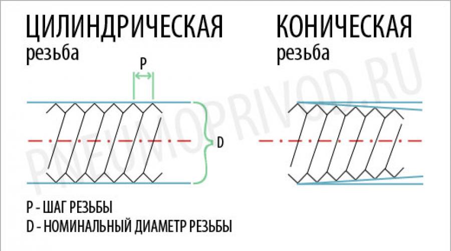
Tapered and cylindrical threads
The rod itself with tapered thread is a cone. Moreover, according to international rules, the taper should be 1 to 16, that is, for every 16 units of measurement (millimeters or inches) with increasing distance from the starting point, the diameter increases by 1 corresponding unit of measurement. It turns out that the axis around which the thread is applied and the conditional straight line drawn from the beginning of the thread to its end along the shortest path are not parallel, but are located at a certain angle to each other. To explain even more simply, if we had a length threaded connection was 16 centimeters, and the diameter of the rod at its starting point would be 4 centimeters, then at the point where the thread ends, its diameter would already be 5 centimeters.
Rod with cylindrical thread is a cylinder, therefore there is no taper.
Thread pitch (metric and inch)
 The thread pitch can be large (or main) and small. Under thread pitch refers to the distance between the threads from the top of the thread to the top of the next thread. You can even measure it using a caliper (although there are also special meters). This is done as follows - the distance between several tops of the turns is measured, and then the resulting number is divided by their number. You can check the measurement accuracy using the table for the corresponding step.
| Cylindrical pipe thread according to GOST 6357-52 | |||||
|---|---|---|---|---|---|
| Designation | Number of threads N by 1" |
Thread pitch S, mm |
Outside diameter thread, mm |
Average diameter thread, mm |
Inner diameter thread, mm |
| G1/8" | 28 | 0,907 | 9,729 | 9,148 | 8,567 |
| G1/4" | 19 | 1,337 | 13,158 | 12,302 | 11,446 |
| G3/8" | 19 | 1,337 | 16,663 | 15,807 | 14,951 |
| G1/2" | 14 | 1,814 | 20,956 | 19,754 | 18,632 |
| G3/4" | 14 | 1,814 | 26,442 | 25,281 | 24,119 |
| G7/8" | 14 | 1,814 | 30,202 | 29,040 | 27,878 |
| G1" | 11 | 2,309 | 33,250 | 31,771 | 30,292 |
Nominal thread diameter
The labeling usually contains nominal diameter, which in most cases is taken to be outside diameter thread. If the thread is metric, then you can use a regular caliper with scales in millimeters to measure. Also, the diameter, as well as the thread pitch, can be viewed using special tables.
Metric and inch threads with examples
 Metric thread– has the designation of the main parameters in millimeters. For example, consider an elbow fitting with an external cylindrical thread. EPL 6-GM5. IN in this case EPL says that the fitting is angled, 6 is 6 mm - the outer diameter of the tube connected to the fitting. The letter “G” in its marking indicates that the thread is cylindrical. “M” indicates that the thread is metric, and the number “5” indicates the nominal diameter of the thread, equal to 5 millimeters. Fittings (from those we have on sale) with the letter “G” are also equipped with a rubber o-ring, and therefore do not require fum tape. The thread pitch in this case is 0.8 millimeters.
Main settings inch thread, according to the name, are indicated in inches. This can be a 1/8, 1/4, 3/8 and 1/2 inch thread, etc. For example, let's take a fitting EPKB 8-02. EPKB is a type of fitting (in this case a splitter). The thread is conical, although there is no reference to this using the letter “R”, which would be more correct. 8 - indicates that the outer diameter of the connected tube is 8 millimeters. A 02 - that the connecting thread on the fitting is 1/4 inch. According to the table, the thread pitch is 1.337 mm. The nominal thread diameter is 13.157 mm.
The profiles of conical and cylindrical threads coincide, which allows you to screw together fittings with tapered thread and cylindrical.
The description of pipe diameters contains data on all parameters - internal, external, conditional, nominal. Knowledge of the characteristics is required when installing the network and selecting fittings. Otherwise it's wrong collected communication threatens loss of tightness, short term operation due to breakdowns. Next, consider the pipe diameters in inches and millimeters.
Dimensional characteristics of pipes
They are reflected in the relevant GOSTs and TUs and contain the following definitions:
- The outer diameter is the main characteristic of the pipe.
- Inner diameter.
- Nominal.
- Conditional pass.
More details about the differences:
- Outside diameter classified into small, medium and large values– which is why the pipe is used in appropriate conditions. Small diameters are used in residential and private water supply systems, medium diameters are used in city communications, and large diameters are used in industrial ones. Outer diameter – most important characteristic pipes, since the required fitting thread is determined from it. Designation – Dн.
- Inner diameter or true. It depends on the thickness of the wall and can differ strikingly from the external one, even if the dimensions of the latter remain unchanged. Designated as Din. It is calculated mathematically (Dн – 2S), where S is the thickness of the pipe wall. Example - the outer diameter of the pipe is 60 mm. Minus the 4 mm walls, its internal diameter will be 52 mm. As the wall thickness increases, the internal parameter decreases.
- The nominal bore or diameter of the pipe lumen is marked as Dу. This is the average value of the internal diameter, rounded to big side to the standard setting. For example, the outer diameter of the pipe will be 159 mm. The true internal diameter after subtracting the wall thickness of 5 mm is 149. Then the nominal diameter after rounding is 150 mm. This parameter is considered to select suitable fittings and fittings.
- Nominal diameter. The concept was introduced to standardize the marking of pipes made of different materials. The value is equal to the nominal diameter and is marked in inches. This allows you to correctly select pipes from various raw materials for combining in a network - steel and plastic are marked in inches, copper and aluminum - in millimeters.
Thus, the correct selection of components for home communications in accordance with the described concepts is not difficult. Tables for converting sizes from inches to millimeters and vice versa will help in self-repair and replacement of defective sections of networks.
Table of diameter sizes in diameters and millimeters
|
Nominal diameter (Dy) of the pipe, in mm |
The diameter of its thread (G), in inches |
Outer diameter (Dh), pipes, mm |
||
|
Steel seam pipe, water and gas supply |
Seamless steel pipe |
|||
Complete table of pipe diameters
| Diameters, inch | Diameters, mm |
| 1/2 | d15 |
| 3/4 | d20 |
| 1' | d25 |
| 1’/1/4 | d32 |
| 1’/1/2 | d40 |
| 2′ | d50 |
| 2’/1/2 | d65 |
| 3′ | d89 |
| 4' | d100 |
| Inch | Millimeter | Inch | Millimeter |
| 1/64 | 0,397 | 33/64 | 13,097 |
| 1/32 | 0,794 | 17/32 | 13,494 |
| 3/64 | 1,191 | 35/64 | 13,891 |
| 1/16 | 1,587 | 9/16 | 14,287 |
| 5/64 | 1,984 | 37/64 | 14,684 |
| 3/32 | 2,381 | 19/32 | 15,081 |
| 7/64 | 2,778 | 39/64 | 15,478 |
| 1/8 | 3,175 | 5/8 | 15,875 |
| 9/64 | 3,572 | 41/64 | 16,272 |
| 5/32 | 3,969 | 21/32 | 16,669 |
| 11/64 | 4,366 | 43/64 | 17,066 |
| 3/16 | 4,762 | 11/16 | 17,462 |
| 13/64 | 5,159 | 45/64 | 17,859 |
| 7/32 | 5,556 | 23/32 | 18,256 |
| 15/64 | 5,953 | 47/64 | 18,653 |
| 17/64 | 6,747 | 49/64 | 19,447 |
| 9/32 | 7,144 | 25/32 | 19,844 |
| 19/64 | 7,541 | 51/64 | 20,241 |
| 5/16 | 7,937 | 13/16 | 20,637 |
| 21/64 | 8,334 | 53/64 | 21,034 |
| 11/32 | 8,731 | 27/32 | 21,431 |
| 23/64 | 9,128 | 55/64 | 21,828 |
| 3/8 | 9,525 | 7/8 | 22,225 |
| 25/64 | 9,922 | 57/64 | 22,622 |
| 13/32 | 10,319 | 29/32 | 23,019 |
| 27/64 | 10,716 | 59/64 | 23,416 |
| 7/16 | 11,112 | 15/16 | 23,812 |
| 29/64 | 11,509 | 61/64 | 24,209 |
| 15/32 | 11,906 | 31/32 | 24,606 |
| 31/64 | 12,303 | 63/64 | 25,003 |
Her Majesty the trumpet! Of course, it makes our lives better. Like that:

The key characteristic of any cylindrical pipe is its diameter. It can be internal ( Du) and external ( Dn). Pipe diameter is measured in millimeters, but the unit of pipe thread is inch.
At the junction of the metric and foreign measurement systems, the most questions usually arise.
Besides, it's real existing size internal diameter often does not coincide with Dy.
Let's take a closer look at how we can continue to live with this. A separate article is devoted to pipe threads. Read also about profile pipes, which are used for the construction of structures.
Inches vs mm. Where does the confusion come from and when is a correspondence table needed?

Pipes whose diameter is indicated in inches ( 1", 2" ) and/or fractions of inches ( 1/2", 3/4" ), are a generally accepted standard in water and water-gas supply.
What's the difficulty?
Take dimensions from the pipe diameter 1" (how to measure pipes is written below) and you will get 33.5 mm, which naturally does not coincide with the classic linear table for converting inches to mm ( 25.4 mm).
As a rule, the installation of inch pipes occurs without difficulty, but when replacing them with pipes made of plastic, copper and of stainless steel a problem arises - the size of the designated inch does not match ( 33.5 mm) to his actual size (25.4 mm).
Usually this fact causes bewilderment, but if you look deeper into the processes occurring in the pipe, the logic of the size discrepancy becomes obvious to a layman. It's quite simple - read on.
The point is that when creating water flow The key role is played not by the external, but by the internal diameter, and for this reason it is used for designation.
However, the discrepancy between designated and metric inches still remains, since the internal diameter standard pipe amounts to 27.1 mm, and reinforced - 25.5 mm. The last value is quite close to equality 1""=25,4 but still he is not.
The solution is that to designate the size of pipes, a nominal diameter rounded to a standard value is used (nominal bore Dy). The nominal diameter is selected so that throughput pipeline increased from 40 to 60% depending on the growth of the index value.
Example:
The outer diameter of the pipe system is 159 mm, pipe wall thickness 7 mm. The exact inner diameter will be D = 159 - 7*2= 145 mm. With wall thickness 5 mm size will be 149 mm. However, in both the first and second cases, the conditional passage will have the same nominal size 150 mm.
In situations with plastic pipes To solve the problem of inappropriate dimensions, transition elements are used. If necessary, replace or dock inch pipes with pipes made according to real metric dimensions - copper, stainless steel, aluminum, both outer and inner diameters should be taken into account.

Table of nominal diameter in inches
| Du | Inches | Du | Inches | Du | Inches |
| 6 | 1/8" | 150 | 6" | 900 | 36" |
| 8 | 1/4" | 175 | 7" | 1000 | 40" |
| 10 | 3/8" | 200 | 8" | 1050 | 42" |
| 15 | 1/2" | 225 | 9" | 1100 | 44" |
| 20 | 3/4" | 250 | 10" | 1200 | 48" |
| 25 | 1" | 275 | 11" | 1300 | 52" |
| 32 | 1(1/4)" | 300 | 12" | 1400 | 56" |
| 40 | 1(1/2)" | 350 | 14" | 1500 | 60" |
| 50 | 2" | 400 | 16" | 1600 | 64" |
| 65 | 2(1/2)" | 450 | 18" | 1700 | 68" |
| 80 | 3" | 500 | 20" | 1800 | 72" |
| 90 | 3(1/2)" | 600 | 24" | 1900 | 76" |
| 100 | 4" | 700 | 28" | 2000 | 80" |
| 125 | 5" | 800 | 32" | 2200 | 88" |
Table. Inner and outer diameters. Stacked water/water-gas pipelines, epectros-welded longitudinal, seamless hot-deformed steel and polymer pipes

Table of correspondence between nominal diameter, thread and outer diameters of the pipeline in inches and mm.
|
Nominal pipe diameter Dy. mm |
Thread diameter G". inch |
Pipe outer diameter Dn. mm |
||
|
Water/water-gas pipes GOST 3263-75 |
Epoxy-welded straight-seam steel pipes GOST 10704-91. Seamless hot-deformed steel pipes GOST 8732-78. GOST 8731-74 (FROM 20 TO 530 ml) |
Polymer pipe. PE, PP, PVC |
||
GOST- state standard used in heat - gas - oil - pipelines
ISO- standard for designating diameters, used in plumbing engineering systems
SMS- Swedish standard for pipe diameters and valves
DIN/EN- the main European range for steel pipes according to DIN2448 / DIN2458
DU (Dy)- conditional pass
Size tables polypropylene pipes presented in the next article >>>
Conformity table for nominal pipe diameters with international markings
| GOST | ISO inch | ISO mm | SMS mm | DIN mm | DU |
| 8 | 1/8 | 10,30 | 5 | ||
| 10 | 1/4 | 13,70 | 6,35 | 8 | |
| 12 | 3/8 | 17,20 | 9,54 | 12,00 | 10 |
| 18 | 1/2 | 21,30 | 12,70 | 18,00 | 15 |
| 25 | 3/4 | 26,90 | 19,05 | 23(23) | 20 |
| 32 | 1 | 33,70 | 25,00 | 28,00 | 25 |
| 38 | 1 ¼ | 42,40 | 31,75 | 34(35) | 32 |
| 45 | 1 ½ | 48,30 | 38,00 | 40,43 | 40 |
| 57 | 2 | 60,30 | 50,80 | 52,53 | 50 |
| 76 | 2 ½ | 76,10 | 63,50 | 70,00 | 65 |
| 89 | 3 | 88,90 | 76,10 | 84,85 | 80 |
| 108 | 4 | 114,30 | 101,60 | 104,00 | 100 |
| 133 | 5 | 139,70 | 129,00 | 129,00 | 125 |
| 159 | 6 | 168,30 | 154,00 | 154,00 | 150 |
| 219 | 8 | 219,00 | 204,00 | 204,00 | 200 |
| 273 | 10 | 273,00 | 254,00 | 254,00 | 250 |
Diameters and other characteristics of stainless steel pipes
| Passage, mm | Diameter outer, mm | Wall thickness, mm | Weight of 1 m pipe (kg) | |||
| standard | reinforced | standard | reinforced | |||
| 10 | 17 | 2.2 | 2.8 | 0.61 | 0.74 | |
| 15 | 21.3 | 2.8 | 3.2 | 1.28 | 1.43 | |
| 20 | 26.8 | 2.8 | 3.2 | 1.66 | 1.86 | |
| 25 | 33.5 | 3.2 | 4 | 2.39 | 2.91 | |
| 32 | 42.3 | 3.2 | 4 | 3.09 | 3.78 | |
| 40 | 48 | 3.5 | 4 | 3.84 | 4.34 | |
| 50 | 60 | 3.5 | 4.5 | 4.88 | 6.16 | |
| 65 | 75.5 | 4 | 4.5 | 7.05 | 7.88 | |
| 80 | 88.5 | 4 | 4.5 | 8.34 | 9.32 | |
| 100 | 114 | 4.5 | 5 | 12.15 | 13.44 | |
| 125 | 140 | 4.5 | 5.5 | 15.04 | 18.24 | |
| 150 | 165 | 4.5 | 5.5 | 17.81 | 21.63 | |
Did you know?
What ingenious lamps can you assemble with your own hands from ordinary metal pipe? Anyone can do this!
Which pipe is considered small - medium - large?
Even in serious sources I have seen phrases like: “We take any pipe of average diameter and...”, but no one indicates what this average diameter is.
To figure it out, you should first understand what diameter you need to focus on: it can be internal or external. The first is important when calculating the transport capacity of water or gas, and the second is important for determining the ability to withstand mechanical loads.
External diameters:
From 426 mm is considered large;
102-246 is called average;
5-102 is classified as small.
As for the internal diameter, it is better to look at the special table (see above).
How to find out the diameter of a pipe? Measure!

For some reason this strange question often comes to e-mail and I decided to supplement the material with a paragraph about measurement.
In most cases, when purchasing, it is enough to look at the label or ask the seller a question. But it happens that you need to repair one of the communication systems by replacing pipes, and initially it is not known what diameter the already installed ones have.
There are several ways to determine the diameter, but we will list only the simplest ones:
After obtaining the outer diameter, you can find out the inner one. Only for this you need to know the thickness of the walls (if there is a cut, just measure with a tape measure or other device with a millimeter scale).
Let's assume that the wall thickness is 1 mm. This figure is multiplied by 2 (if the thickness is 3 mm, then it is also multiplied by 2 in any case) and subtracted from the outer diameter (18.85- (2 x 1 mm) = 16.85 mm).
It’s great if you have a caliper at home. The pipe is simply grabbed by the measuring teeth. Required value look at the double scale.
Arm yourself with a tape measure or a measuring tape (this is how women measure their waist). Wrap it around the pipe and record the measurement. Now, to obtain the desired characteristic, it is enough to divide the resulting figure by 3.1415 - this is the number Pi.
Example:
Let's imagine that the girth (circumference L) of your pipe is 59.2 mm. L=ΠD, resp. the diameter will be: 59.2 / 3.1415= 18.85 mm.
Types of steel pipes according to their production method

Electric welded (straight seam)
For their manufacture, strips or sheet steel are used, which are special equipment bend into required diameter, and then the ends are connected by welding.
The effect of electric welding guarantees a minimum seam width, which makes it possible to use them for the construction of gas or water pipelines. The metal is in most cases carbon or low alloy.
Indicators finished products are regulated by the following documents: GOST 10704-91, GOST 10705-80 GOST 10706-76.
Please note that a pipe manufactured in accordance with standard 10706-26 is distinguished by maximum strength among its peers - after creating the first connecting seam, it is strengthened by four additional ones (2 inside and 2 outside).
IN regulatory documentation The diameters of products produced by electric welding are indicated. Their size ranges from 10 to 1420 mm.
Spiral seam
The material for production is steel in rolls. The product is also characterized by the presence of a seam, but unlike the previous production method, it is wider, which means the ability to withstand high internal pressure is lower. Therefore, they are not used for the construction of gas pipeline systems.
A specific type of pipe is regulated by GOST number 8696-74 .
Seamless
Production specific type involves deformation of specially prepared steel blanks. The deformation process can be carried out both under the influence high temperatures, and cold method (GOST 8732-78, 8731-74 and GOST 8734-75, respectively).
The absence of a seam has a positive effect on the strength characteristics - the internal pressure is evenly distributed over the walls (there are no “weak” places).
As for diameters, standards control their production with a value of up to 250 mm. When purchasing products with sizes exceeding those indicated, you have to rely only on the integrity of the manufacturer.
It is important to know!
If you want to buy the maximum durable material, buy seamless cold-formed pipes. The absence of temperature influences has a positive effect on preserving the original characteristics of the metal.
Also if important indicator is the ability to withstand internal pressures, then choose round products. Profile pipes cope better with mechanical loads (they are well made from metal frames and so on.).
Here are a couple more excellent slides of creative advertising for a pipe manufacturer:


MAIN PARAMETERS OF INCH THREADS
(BSW (Ww), BSF, UNC, UNF standards)
The peaks and valleys of the inch thread profile, similar to the metric thread, are cut flat. The pitch of an inch thread is determined by the number of threads (turns) per inch 1", but its apex angle is 55° (Whitworth thread - British standard BSW (Ww) and BSF), apex angle is 60° (American standard UNC and UNF ).
The outer diameter of the thread is measured in inches 1" = 25.4 mm- stroke (") symbol inches. Inch thread is characterized by the number of threads per inch. By American standards inch thread performed with large (UNC) and small (UNF) steps.
NPSM- American standard for inch cylindrical pipe threads.
NPT- American standard for inch conical threads.
Standards:
ASME/ANSI B1.1– 2003 Unified Inch Screw Threads, UN & UNR Thread Form
ASME/ANSI B1.10M– 2004 Unified Miniature Screw Threads
ASME/ANSI B1.15– 1995 Unified Inch Screw Threads, UNJ Thread Form
AMERICAN INCH THREAD
Basic parameters of inch thread:
d(D)– outer diameter of the thread of the bolt and nut, respectively;
d p (D p)– average thread diameter of the bolt and nut, respectively;
d i (D i)– internal diameter of the thread of the bolt and nut, respectively;
n– number of threads per inch.
American thread with coarse pitch - UNS
|
Thread sizes, inches (mm) |
D |
Dp |
D i |
Thread sizes, inches (mm) |
D |
Dp |
D i |
||
|
№1 (1,8542) | |||||||||
|
№2 (2,1844) |
1 (25,4) |
||||||||
|
№3 (2,5146) |
1 1/8 (28,58) |
||||||||
|
№4 (2,8448) |
1 1/4 (31,75) |
||||||||
|
№5 (3,1750) |
1 3/8 (34,925) |
||||||||
|
№6 (3,5052) |
1 1/2 (38,10) |
||||||||
|
№8 (4,1656) |
1 3/4 (44,45) |
||||||||
|
№10 (4,8260) |
|||||||||
|
№12 (5,4864) |
2 (50,8) |
||||||||
|
2 1/4 (57,15) |
|||||||||
|
1/4 (6,3500) |
2 1/2 (63,5) |
||||||||
|
5/16 (7,9375) |
2 3/4 (69,85) |
||||||||
|
3/8 (9,5250) |
|||||||||
|
7/16 (11,1125) |
3 (76,2) |
||||||||
|
1/2 (12,700) |
3 1/4 (82,55) |
||||||||
|
9/16 (14,2875) |
3 1/2 (88,9) |
||||||||
|
5/8 (15,8750) |
3 3/4 (95,25) |
||||||||
|
3/4 (19,0500) |
4 (101,6) |
||||||||
|
7/8 (22,2250) |
|||||||||
American fine pitch thread - UNF
|
Thread sizes, inches (mm) |
D |
Dp |
D i |
Thread sizes, inches (mm) |
D |
Dp |
D i |
||
|
№0 (1,524) |
3/8 (9,525) |
||||||||
|
№1 (1,8542) |
7/16 (11,1125) |
||||||||
|
№2 (2,1844) |
1/2 (12,700) |
||||||||
|
№3 (2,5146) |
9/16 (14,2875) |
||||||||
|
№4 (2,8448) |
5/8 (15,875) |
||||||||
|
№5 (3,1750) |
3/4 (19,050) |
||||||||
|
№6 (3,5052) |
7/8 (22,225) |
||||||||
|
№8 (4,1656) |
|||||||||
|
№10 (4,8260) |
1 (25,4) |
||||||||
|
№12 (5,4864) |
1 1/8 (28,58) |
||||||||
|
1 1/4 (31,75) |
|||||||||
|
1/4 (6,350) |
1 3/8 (34,925) |
||||||||
|
5/16 (7,9375) |
1 1/2 (38,10) |
||||||||
American thread with extra fine pitch – UNEF
|
Thread sizes, inches (mm) |
D |
Dp |
D i |
Thread sizes, inches (mm) |
D |
Dp |
D i |
||
|
№12 (5,4864) |
|||||||||
|
1 (25,4) |
|||||||||
|
1/4 (6,350) |
1 1/16 (26,987) |
||||||||
|
5/16 (7,9375) |
1 1/8 (28,58) |
||||||||
|
3/8 (9,525) |
1 3/16 (30,162) |
||||||||
|
7/16 (11,1125) |
1 1/4 (31,75) |
||||||||
|
1/2 (12,700) |
1 5/16 (33,337) |
||||||||
|
9/16 (14,2875) |
1 3/8 (34,925) |
||||||||
|
5/8 (15,875) |
1 7/16 (36,512) |
||||||||
|
11/16 (17,462) |
1 1/2 (38,10) |
||||||||
|
3/4 (19,050) |
1 9/16 (39,687) |
||||||||
|
13/16 (20,637) |
1 5/8 (41,27) |
||||||||
|
7/8 (22,225) |
1 11/16 (42,86) |
||||||||
|
15/16 (23,812) |
|||||||||
Thread sizes are the outer diameter of the thread, expressed in fractional fractions of an inch. One of the main characteristics of an inch screw thread is the number of turns per inch of thread length (n). The number of turns and thread pitch P are related by the relation:
American standards provide two thread forms:
A thread with a flat recess, which is designated by the letters UN;
- thread with a radius cavity, which is designated by the letters UNR.
The standard defines three classes of thread accuracy. These classes are designated as 1A, 2A, 3A, 1B, 2B, 3B. Accuracy classes 1A, 2A, 3A refer to external threads; accuracy classes 1B, 2B, 3B refer to internal threads. Accuracy class 1A, 1B is the coarsest and is used in cases where quick and easy assembly is required, even with partially dirty and dented threads. Accuracy class 2A, 2B are the most common and are used for threads general purpose. Accuracy class 3A, 3B imposes the most stringent requirements on threads and is used in cases where it is necessary to ensure a minimum clearance in a threaded connection.
Thread designation. First, the nominal size is written down, then the number of threads per inch of thread, thread group symbols and accuracy class symbol. The letters LH at the end of the entry indicate left-hand thread. Nominal size is the outside diameter, defined as a fractional size or thread number, or their decimal equivalent.
For example: 1/4 – 20UNS – 2A or 0.250 – 20UNC – 2A
BRITISH STANDARD INCH THREADS
(BSW (Ww) and BSF)
| Designation threads | BSP size in |
thread pitch | largest diameter | smallest diameter | A/F mm |
length mm |
pipes | thread hole diameter (for drill) mm |
||||||||
| in (TPI) |
mm | mm | in | mm | in | DN mm |
O.D. mm |
O.D. in |
thickness mm |
BSP.PL (Rp) |
BSP.F (G) |
|||||
| -1 | 1 / 16 | 28 | 0,907 | 7,723 | 0,304 | 6,561 | 0,2583 | 4±0.9 | 6,60 | 6,80 | ||||||
| -2 | 1 / 8 | 28 | 0,907 | 9,728 | 0,383 | 8,565 | 0,3372 | 15 | 4±0.9 | 6 | 10,2 | 0,40 | 2 | 8,60 | 8,80 | |
| -4 | 1 / 4 | 19 | 1,337 | 13,157 | 0,518 | 11,445 | 0,4506 | 19 | 6±1.3 | 8 | 13,5 | 0,53 | 2,3 | 11,50 | 11,80 | |
| -6 | 3 / 8 | 19 | 1,337 | 16,662 | 0,656 | 14,950 | 0,5886 | 22/23 | 6.4±1.3 | 10 | 17,2 | 0,68 | 2,3 | 15,00 | 15,25 | |
| -8 | 1 / 2 | 14 | 1,814 | 20,955 | 0,825 | 18,633 | 0,7336 | 27 | 8.2±1.8 | 15 | 21,3 | 0,84 | 2,6 | 18,75 | 19,00 | |
| -10 | 5 / 8 | 14 | 1,814 | 22,911 | 0,902 | 20,589 | 0,8106 | 16 | 2,6 | - | 21,00 | |||||
| -12 | 3 / 4 | 14 | 1,814 | 26,441 | 1,041 | 24,120 | 0,9496 | 32 | 9.5±1.8 | 20 | 26,9 | 1,06 | 2,6 | 24,25 | 24,50 | |
| -16 | 1 | 11 | 2,309 | 33,249 | 1,309 | 30,292 | 1,1926 | 43 | 10.4±2.3 | 25 | 33,7 | 1,33 | 3,2 | 30,40 | 30,75 | |
| -20 | 1 1 / 4 | 11 | 2,309 | 41,910 | 1,650 | 38,953 | 1,5336 | 53 | 12.7±2.3 | 32 | 42,4 | 1,67 | 3,2 | 39,00 | 39,50 | |
| -24 | 1 1 / 2 | 11 | 2,309 | 47,803 | 1,882 | 44,846 | 1,7656 | 57 | 12.7±2.3 | 40 | 48,3 | 1,90 | 3,2 | 45,00 | 45,00 | |
| -32 | 2 | 11 | 2,309 | 59,614 | 2,347 | 56,657 | 2,2306 | 70 | 15.9±2.3 | 50 | 60,3 | 2,37 | 3,6 | 56,75 | 57,00 | |
| -40 | 2 1 / 2 | 11 | 2,309 | 75,184 | 2,960 | 72,227 | 2,8436 | 17.5±3.5 | 65 | 76,1 | 3,00 | 3,6 | ||||
| -48 | 3 | 11 | 2,309 | 87,884 | 3,460 | 84,927 | 3,3436 | 20.6±3.5 | 80 | 88,9 | 3,50 | 4 | ||||
| -64 | 4 | 11 | 2,309 | 113,030 | 4,450 | 110,073 | 4,3336 | 25.5±3.5 | 100 | 114,3 | 4,50 | 4,5 | ||||
| -80 | 5 | 11 | 2,309 | 138,430 | 5,450 | 135,472 | 5,3335 | 28.6±3.5 | 125 | 139,7 | 5,50 | 5 | ||||
| -96 | 6 | 11 | 2,309 | 163,830 | 6,450 | 160,872 | 6,3335 | 28.6±3.5 | 150 | 165,1 | 6,50 | 5 | ||||
Related documents:
GOST 3469-91 - Microscopes. Lens thread. Dimensions
GOST 4608-81 - Metric thread. Preference fits
GOST 5359-77 - Eyepiece thread for optical instruments. Profile and dimensions
GOST 6042-83 - Edison round thread. Profiles, dimensions and limits
GOST 6111-52 - Conical inch thread with a profile angle of 60 degrees
GOST 6211-81 - Tapered pipe thread
GOST 6357-81 - Cylindrical pipe thread
GOST 8762-75 - Thread round diameter 40 mm for gas masks and calibers for it. Main Dimensions
GOST 9000-81 - Metric threads for diameters less than 1 mm. Tolerances
GOST 9484-81 - Trapezoidal thread. Profiles
GOST 9562-81 - Single-start trapezoidal thread. Tolerances
GOST 9909-81: Tapered thread of valves and gas cylinders
GOST 10177-82 - Persistent thread. Profile and main dimensions
GOST 11708-82 - Thread. Terms and Definitions
GOST 11709-81 - Metric thread for plastic parts
GOST 13535-87 - Reinforced thrust thread 45 degrees
GOST 13536-68 - Round thread for sanitary fittings. Profile, main dimensions, tolerances
GOST 16093-2004 - Metric thread. Tolerances. Landings with clearance
GOST 16967-81 - Metric threads for instrument making. Diameters and pitches
GOST 24737-81: Single-start trapezoidal thread. Main Dimensions
GOST 24739-81 - Multi-start trapezoidal thread
GOST 25096-82 - Persistent thread. Tolerances
GOST 25229-82 - Metric tapered thread
GOST 28487-90: Conical locking threads for drill string elements. Profile. Dimensions. Tolerances