Sliding gates without counterweight design. Types of sliding gates. By way of opening
If there is not enough space in front of the entrance, the best solution would be to install a welded sliding gate. They do not need a place to open the valves, like those, and in winter they do not have to wave a shovel, clearing snowdrifts. If desired, anyone who is friendly with welding will make sliding gates with their own hands.
Structurally, sliding gates are divided into cantilever, suspended, rail types. The easiest to make is the last option. In this design, the sash with rollers fixed from below moves along a rail laid in the ground. Due to the fact that you have to constantly clean the rail from snow, dirt, foreign objects, they are rarely used.
In suspended structures, the canvas with the help of rollers moves along a beam installed at the top on supports on the sides of the gate. The system is reliable and durable, does not require constant maintenance, but incoming vehicles are limited in height. However, varieties with removable beams solve this problem.
Despite the complexity of manufacturing and higher cost, the design of welded sliding gates of the cantilever type is most often chosen. Their basis is a beam with an installed canvas, which moves along the rollers located on the side of the opening. For installation on the opening side, a free space of 1.5 times the leaf width is required.

We determine the dimensions and design the drawing
To correctly draw up a drawing, you can use the finished scheme taken on the Internet. First you need to decide on the width of the opening, since the rest of the dimensions depend on it. With a perpendicular entry, a passenger car will need 2.5 - 3 m. A truck or tractor will need at least 3.5 m. If entry is possible only at an angle, the width increases by one and a half times. For safety reasons, the distance from the most protruding elements of the car to the support pillars is chosen at least 30 - 50 cm. The optimal width of the opening, sufficient for convenient passage of all types of transport, will be 4.5 m.
The width of the sash is made 20 cm larger than the size of the opening, so that there are no gaps on the sides when closing. When installed, the lower edge of the sash is raised 10 cm from the ground. When drawing up the drawings, it is also necessary to take into account the thickness of the support beam so that the height of the gate is flush with the fence.
So that the sash does not fall down during movement, a slope is welded to it, used as a counterweight. Its length is made equal to 0.5 of the width of the canvas. The entire load is taken by the supporting carts, so they are attached to the channel, installed on a solid concrete foundation. It is also used for mounting an electric drive for remote opening gates.

Choosing materials and accessories
Fittings are difficult to make at home, so it's easier to buy. The choice of components depends on the dimensions and weight of the gate. Manufacturers offer options designed for certain parameters:
- weight no more than 400 kg, width up to 4 m;
- weight up to 600 kg, size no more than 6 m;
- weight over 600 kg, width over 6 m.
When installing sliding gates yourself, you will have to purchase:
- lower guide beam;
- supporting bracket, rubber rollers are installed on it;
- a pair of support carts with platforms for them;
- end roller;
- lower and upper traps;
- plastic plugs.

You can sheathe the gate with corrugated board, sheet iron, clapboard, polycarbonate. For gates 4 m wide you will also need:
- profile pipes 50×50 or 60×40 mm for frame assembly;
- pipe 40 × 20 for assembling the frame for sheathing;
- 20th channel 2 m long for mounting roller carts;
- pieces of sheet iron for mortgages on brick or stone supports;
- reinforcing bars with a diameter of 10 - 12 mm for installing a channel on the foundation;
- when self-mixing the concrete solution, you need to stock up on crushed stone, sand, cement;
- paint and primer for metal.
How to make a sliding gate with your own hands: step-by-step instructions
To prevent the design from turning out in the form of a propeller, welding of sliding gates must be carried out on a flat area. Since the work will have to be done in stages, it is necessary at every step to control the correct manufacture and assembly of structural elements.
We install poles
Supports are made of wood, channel, shaped pipes, brick, stone. They are installed to a depth of at least a meter, but it is more reliable to equip a common foundation. Welding is used to mount the traps and the supporting bracket, so sheet metal embeds are installed on stone and brick supports. Holes no less than 50 × 50 cm in size are dug under the pillars. After installation, the verticality is checked, concrete is poured.
We mount the foundation
A foundation pit 0.5 m wide and 30 cm longer than the counterweight is dug next to the fence. The bottom of the trench should be below the freezing point of the soil. Further:
- rods are cut from the reinforcement with a length equal to the depth of the pit and 20 cm each;
- long rods are welded to the sides of the channel in 50 cm increments;
- opposing rods are welded in pairs at a distance of 0.7 - 0.8 m from the channel;
- after installing the structure made in the pit, the channel is aligned horizontally so that its upper shelf is flush with the driving surface;
- formwork and additional reinforcement are installed on the sides;
- trench is filled with concrete.
![]()
Welding the gate leaf
To weld a gate from a professional pipe, they are cut in accordance with the drawing of the workpiece. Then:
- A 50 × 50 mm lower pipe is welded to the guide beam, and vertical racks are welded to it. Next, the upper cross member and counterweight are mounted.
- The internal space of the frame is filled with frame elements from a 40 × 20 pipe for attaching the skin. To prevent overheating and deformation, they must be welded in a checkerboard pattern.
- Welding seams are cleaned with a grinder, the structure is primed, painted.

We install the gate
For ease of installation, between the supports, at a distance from them equal to the thickness of the sash, a cord is pulled. The height above the driveway is 15 - 20 cm. It will be used as a center line when installing support carts.
Assembly is carried out in the following order:
- Places are marked for roller carts on the channel. To prevent the end roller on the guide from protruding into the passage, the first trolley is placed 15 cm from the edge of the opening. The rear one is located at a distance equal to the length of the frame (including the counterweight) minus 10 cm, measured from the receiving support.
- After tacking the platforms, roller carts are placed on them.
- The sash is installed, its position relative to the pillars is checked. If everything is fine, the canvas and carts are removed.
- Support platforms are scalded.
- The trolleys and the sash are installed, the gates are closed.
- The level checks the horizontal. If necessary, the position is corrected by adjusting bolts on the platforms.
- The end roller is inserted into the end of the guide, fixed with bolts, tacked by welding.
- A support bracket is welded onto the support standing next to the carts so that the upper edge of the sash is inside it. The rollers set the position of the sash vertically.
- The lower catcher is put on the end roller, the gate is closed, a place is marked on the receiving support. Fastening is done on bolts so that it is possible to adjust the height.
- The upper catcher is installed in the same order, but it is fastened by welding.
- The installation is completed with the final adjustment of the rollers, traps, supporting brackets. The end of the guide is closed with a plug.

Sewing and painting gates
Sheathing made of sheet materials is fastened with self-tapping screws or rivets. Under them, in the elements of the sliding gate frame, holes are drilled. When sheathed with a picket fence or clapboard, they must be treated with an antiseptic before painting. Forged elements are used alone or in combination with other materials.
Decking and polycarbonate are pre-selected by color. Sheet iron and forged parts are pre-degreased and coated with an anti-corrosion primer. Painting is done with alkyd enamel or acrylic paint in 2-3 layers. The work is done with a spray gun, roller or brush.
What you need to automatically open sliding gates
To equip sliding gates with an automation system, you can buy a ready-made kit or purchase components separately. The set should consist of the following elements:
- gear rack;
- electric drive;
- signal lamp;
- photocells;
- remote control;
- control unit.
To install the drive, a channel is used, on which support carts are mounted. Installation is carried out in the following order:
- By attaching a gear rack to the bottom tube of the frame and aligning it with the gear teeth, the location of the drive between the carts is determined. If you need to lift it or install it next to the channel, a thick metal plate is welded to it.
- The base of the drive is welded to the prepared place, the device itself is attached to it.
- Having opened the gate and installed the rail, the correctness of its position is checked. In any extreme position, a margin of 10 cm should remain. Then it is welded.
- Limit switches and photocells are attached to the rail.
- A signal lamp is installed on the left support.
The elements are connected by cables in accordance with the instructions or diagram, testing is carried out. If the weight of the gate is small, a screwdriver is suitable as a drive, and the control unit is replaced by a cheap car alarm system.

Since it is not easy to make sliding gates with your own hands, it is worth listening to the recommendations of professionals:
- If you need to cut a gate into the gate, it must be mounted closer to the foundation with a channel to reduce the load on the rollers.
- In order not to make a mistake with determining the width of the opening, you must first drive pegs into the installation sites of the pillars and try to drive through.
- The seller can offer carts with plastic rollers. They make less noise than metal, but do not last long. Therefore, preference should be given to rolling bearings made of durable steel.
- If for welded sliding gates the counterweight is made rectangular, its length can be reduced to 1/3 of the leaf width. This is true when there is not enough space to open.
Self-welded sliding gates will cost much less than those ordered from the company that produces them. At the same time, the quality of the work performed depends only on oneself. The result is a reliable and easy-to-use design that provides comfortable travel using remote control.
In this article, we will tell you about all the intricacies of construction and installation, as well as all the possible problems that you may encounter if you decide to make a sliding gate with your own hands. When faced with the task of installing a sliding gate for the first time, the biggest mystery is the drawing of a sliding gate. In fact, the design of sliding gates is very simple, their installation scheme is also not complicated, and below we will describe the basic principles for installing sliding gates, having understood which you will no longer have questions about how to install them yourself. But first things first.
Sliding gates. We consider the optimal width of the opening
This is the most important question that you must answer to yourself first of all. Under the width of the sliding gate, we mean the width of the gate itself, i.e. free distance between the gate posts when the gate is fully open. To answer this question, you need to decide on just a few points:
- Which vehicles will enter through these sliding gates? Only cars? Gazelles? Tractor? Kamaz?
- At what angle will all these vehicles, especially trucks, enter?
According to my own feelings, sliding gates should be so wide that when passing through them, there is a gap of at least 30 cm on each side between the gate posts and mirrors (or better, all 50 cm.) And now some statistics about the width of some cars (including mirrors).
- Ford focus 3 = 2.01 m.
- Ford Explorer 2015 = 2.29 m.
- Gazelle (all-metal van) = 2.5 m.
- KamAZ = 2.9 m.
Just don't say that you have already built everything and no more trucks will ever come to your site. I assure you that in life there will be enough situations in which you will need to let trucks into your site. And now let's answer the question of at what angle such cars can drive towards you? According to statistics, the angle of entry of such cars into the site is 45 degrees to the goal line. See for yourself, the length of a typical KamAZ 65111 is 7.34 meters, and now go to the place on your site where you plan to install sliding gates, look at the space behind them and try to answer the question of whether this space is enough for the truck to in order to turn around and drive into your sliding gate at right angles to the goal line?
If we turned out to be right and the angle of entry of the truck will be approximately 45 ° to the gate line, then according to the Pythagorean theorem, in order for a KamAZ 2.9 meters wide to pass into the target of your gate at an angle of 45 degrees WITHOUT A GAP AT ALL between the mirrors and the gate posts, the width of the gate should be 4.1 meters. However, we do not recommend using this figure because, firstly, it does not take into account the gap, and secondly, there are situations when a car passing through the gate can either swing for any reason or slide to the side on snow, ice or dirt, slip and move to the side, etc. Based on these considerations, we recommend installing sliding gates with an opening width of at least 4.5 meters.
If we move from theory to practice, then our own experience suggests that the optimal gate width is 4.5 meters, and the ideal gate width is 5 meters.
Please note that everything written above referred to the width of the gate opening, but not the width of the gate leaf! If we talk about the door leaf, then there is one important point that needs to be considered. The width of the door leaf should be approximately 20 centimeters larger than the width of the gate opening! Otherwise, when the gate is closed, you will have a gap visible at an angle to the plane of the gate (see photo below). If you forgot to ask for the door leaf to be made a little wider than the planned opening width, you can correct the situation by installing the gate posts a little closer to each other than planned. Thus, you will reduce the width of the opening by about 15-20 centimeters, but you will avoid the formation of a gap.

Sliding gates. Nuances with the height of the sliding gate
It may seem to many that this moment is not worth attention and discussion at all, but this is not so. We partly agree. Indeed, ignoring this moment will not create any significant problems for you. apart from aesthetic. Many people think that if the height of the fence leaf adjacent to the gate is 2 meters, then the height of the gate leaf should be 2 meters. In reality, this is not so. Let's look at an example:
- We have a fence made of profiled sheet, having a height of 2 meters and installed without tape and without a gap at the bottom. In this case, the profiled sheet rises directly from the ground to a height of 2 meters. (we published an article on installing a fence earlier: Fence posts. We build a fence without mistakes with our own hands)
- When ordering or making your own door leaf frame, you are guided by the same profiled sheet, which has the same height as that of the fence - 2 meters, right?
Now let's see what happens as a result. In both cases, you are guided by the same height of the profiled sheet, but you do not take into account the fact that in the case of a fence, the profiled sheet starts directly from the ground and its upper edge is at a height of exactly 2 meters above the ground. At the same time, in the case of gates, the lower edge of the sliding gate cannot touch the ground, it is raised by about 10 cm from the ground.
In fairness, it should be noted that the gap between the ground and the lower part of the gate is adjusted using the adjusting pads, which are standardly included in the set of rollers (see photo on the right and photo below). The roller supports are put on and fastened to the adjusting platforms with the help of nuts, and with the help of the same nuts, the installation height of the roller supports (and hence the gate frame) can be adjusted within 5 cm. As a result, the minimum distance from the ground will be 10 cm, the maximum - 15 cm from the ground.
Move on. Unlike a fence, the profiled door leaf is usually inserted into the profile that makes up the frame of the door leaf, while the profile is usually welded from a 60/40 mm rectangular pipe. The gate height has already come up: 100mm + 40mm + 2000mm + 40mm = 2180mm. But that's not all, since a guide beam with a height of 60 mm is welded to the door leaf from below (for gates weighing up to 350 kg). In total, taking into account the guide beam, the distance from the ground surface to the top edge of the gate is already 2180 mm + 60 mm = 2240 mm. As you can see, according to the calculations, the top edge of the gate was 24 cm higher than the top edge of the fence!
For reference: the dimensions of the guide beams that come with the rollers and other accessories for sliding gates vary (). Each set has its own name, and is used depending on the size and weight of the gate:
- MICRO set: sliding gates with opening up to 4m and weight up to 300kg inclusive; dimensions of the MICRO guide beam - height 55mm, width 60mm, thickness 3mm, standard length 4.5m / 5.3m / 6m;
- ECO set: sliding gates with opening up to 5m and weight up to 500kg inclusive; dimensions of the ECO guide beam - height 60mm, width 70mm, thickness 3.5mm, standard length 5m / 6m / 7m;
- EURO set: sliding gates with opening up to 6m and weight up to 800kg inclusive; dimensions of the EURO guide beam - height 75mm, width 90mm, thickness 4.5mm, standard length 6m / 7m / 8m / 9m;
- MAX set: sliding gates with opening up to 12m and weight up to 2000kg inclusive; guide beam dimensions MAX - height 135mm, width 130mm, thickness 5mm, standard length 6m / 9m;
To avoid such an aesthetic mistake, the height of the sliding gate frame should be made focusing not on the height of the filling profiled sheet, but on the height of the fence adjacent to the gate.


Sliding gates. Drawing and scheme of sliding gates.
Sliding gates have such a simple design that you do not need any drawing of the gate. Below we will explain to you the scheme of operation of sliding gates, after which you will easily understand their design, what depends on what in it, what and how it can be changed at your discretion. So, the basis of the entire design of sliding sliding gates are 2 rollers and a guide beam moving along them (sometimes called a “guide rail”). Look at the photo below.


The guide, moving along the rollers, is the basis of the whole structure. The guide is welded from below to the gate frame and now the entire frame moves along the rollers. Since the rollers should not be in the gate opening, so as not to get in the way underfoot, they are taken out to the side, outside the gate opening, and the sliding gates are respectively lengthened by the so-called "counterweight". The generally accepted design is one in which the length of the "counterweight" is equal to half the length of the gate opening. In other words, for a gate opening of 5 meters, the total frame length will be 5 + 5/2 = 7.5 meters. At the same time, 2.5 meters in this frame will be the very “counterweight”, which is a flight outside the gate opening and relies on rollers.
Strictly speaking, it is generally accepted that the length of the counterweight of the gate is 1/3 - 1/2 of the length of the opening. But we strongly recommend making the counterweight 1/2 of the length of the gate opening. Why? Because people very often make a “lightweight” counterweight - a triangle (as in the figure below). As a result, not only do they reduce the length of the counterweight to 1/3 of the length of the opening, they also truncate the "counterweight" to a triangle, thereby reducing its weight. In this case, it simply ceases to perform the function counterweight- it's too easy. As a result, the sliding gates will be “out of balance”, “peck” when closing and when fully opened, and all the loads just fall on the rollers, which fly out of this in 2-3 years, and not in 10 years, as they should . Bottom line: if the counterweight is “square”, then, in principle, 1/3 of the opening is enough. If "triangular" - then 1/2 of the opening. But the ideal option would still be a counterweight length equal to 1/2 the length of the gate opening.
That is why the basis for installing the gate is the installation of rollers. It is the rollers that hold the entire structure and experience the greatest loads in comparison with all other structural elements of sliding sliding gates. These two rollers hold the entire door leaf overhanging, so they are installed on a massive reinforced concrete foundation, into which, for convenience, an embedded part made of a channel is poured. This is done to simplify the subsequent installation of the rollers, and it is to it that the bases of the two rollers are subsequently welded, and even later - the base for mounting the engine of the rollback mechanism. (see photo above).
All other components for sliding gates practically do not carry power loads and serve to keep the door leaf from swinging. All of these sliding gate accessories are shown below. Of these, the supporting rail (square bracket with two rubber rollers), the lower catcher and the upper catcher are mounted on poles.

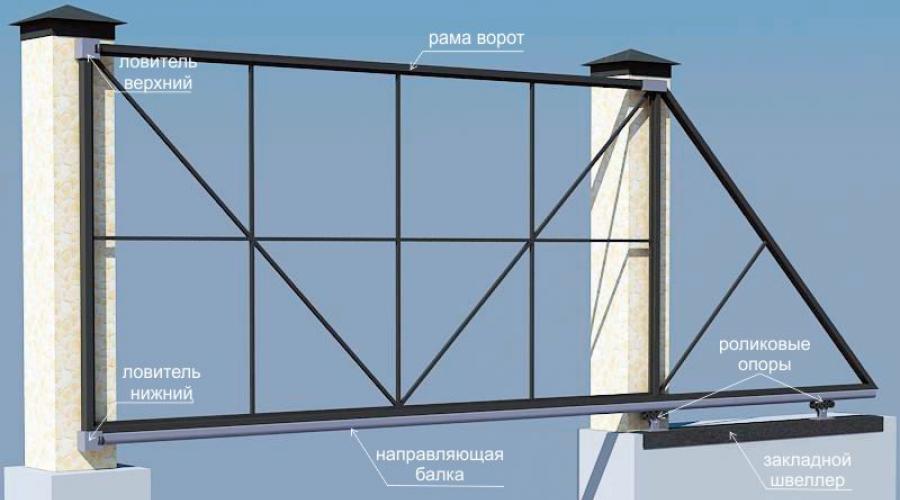
Let's take a look at the entire set of accessories needed to install sliding gates. Look at the diagram below, in which we numbered all the elements. So, element by element, according to the numbering on the diagram:

- End cap for the rear of the rail. Its purpose is partly decorative, partly to prevent snow from stuffing into the guide when the gate rolls back in winter if it rolls back, clearing the snow;
- Support rail with two adjustable rollers (square bracket with two rubber rollers). It is installed at the top of the post (closest to the mortgage with bearing rollers) and simply keeps the door leaf in a vertical position from swinging and tipping over;
- Top catcher. It is installed on the "receiving" post. The role of the catcher is to keep the door leaf from swinging when the sliding gates are closed;
- Bottom catcher. Almost the same as in the previous paragraph, but with a support platform on which the support roller rolls when the sliding gate is completely closed. The point is not only to keep the sliding gate from swinging, but also to unload the drive rollers and the guide, which experiences strong bending loads when the gate is fully extended;
- Support roller. This roller is both a damper and a plug for the front edge of the guide. When closing the gate, it rolls into the “lower catcher” (see previous paragraph No. 4), dampens the impact of the closing gate leaf, rests with its roller on the “lower catcher” support platform, removing bending loads from the guide and the entire door leaf;
- Actually the guide itself (or “guide rail”), thanks to which the sliding gates move back and forth along the rollers (rollers on the scheme of sliding gates under No. 7). As we wrote above, the guide is plugged from the back side by element No. 1, from the front side by element No. 5.
- Support rollers with adjustable stands are the elements that carry the main load and ensure the rolling of the sliding gate. In fact, these are the most powerful structural elements that require fixing on a solid foundation in the form of a mortgage, usually mounted on a reinforced concrete foundation.
Adjustment stands are used for:
- accurate alignment of the roller bearings in one straight line (if the rollers do not stand in a straight line, they will wear out a lot. Without adjusting stands, the rollers are almost impossible to set up straight)
- adjustment of the gate installation height relative to the ground (within 5 cm)
- the possibility of replacing worn out roller bearings (if the roller bearings were welded to the mortgage without adjusting stands, then it would be problematic to replace them without using the “grinder” of the welding machine).
Installing sliding gates. Mortgage, foundation, pillars.
For many, the embedded element raises many questions, since the shape and dimensions of this embedded part are not clear and everyone starts looking for its drawing. You don't need a drawing. The meaning of this element is only to prepare a certain basis on a concrete base for the subsequent installation of rollers and a gate drive using electric welding. Based on this, the shape does not matter at all, the dimensions may vary. The channel No. 10, 12.14, 16, 20 is taken as a mortgage. The more massive the sliding gate, the more powerful the channel. The mortgage must stand directly on the line of movement of the canvas of the future gate, the platform for the engine is shifted from this line into the yard.

Look at the photo below. As you can see, rollers are mounted on the embedded element (in the photo they are under the numbers 1 and 2). The same photo shows that it would be more logical to move roller No. 2 to the right, closer to the right edge of the gate frame (the attachment point is determined with the gate fully closed).
It would seem that, ideally, roller No. 1 would have to stand at the very post (which is in the photo on the left), and roller No. 2 should melt at the very edge of the guide rail, closer to the edge of the gate frame (in the photo on the right). This is almost true, but there is one caveat! The fact is that the guide beam has elements inserted inside at the edges. The edge of the beam farthest from the gate opening is closed with an end cap (in the photo at number 4), and an auxiliary support roller is inserted into the opposite edge (in the photo at number 3), which rolls into the lower catcher when the gate is closed. Therefore, rollers no. 1 and no. 2 must be set at the appropriate distances. The length of the embedded element can be equal to the length of the "counterweight" of the gate. That is, with a gate opening width of 5 meters and a "counterweight" width of 2.5 meters, the length of the mortgage can be approximately 2.3 - 2.5 meters. To install a drive with an electric motor in the future, weld a pad to the embedded element anywhere. On the other hand, you can not do this and subsequently weld a plate protruding sideways to the mortgage on top and put the drive on it.

Now about the foundation. The foundation of sliding gates is perhaps the most important and critical part of the entire gate structure. First of all, the foundation is needed for the mortgage, to which the main support rollers will be attached. Some firms and private teams offer a cheaper version of the foundation than reinforced concrete, namely, they offer to twist several screw piles, on which a mortgage is then welded on top and that's actually almost everything is ready. Further nearby, another one is screwed a little crookedly into this bunch of piles (since you can’t screw a whole bush of piles exactly next to it), under the pole. We will not even consider such an option. Perhaps it fits under small and light sliding sliding gates, for example, having a length of 3 meters with a light frame sheathed with a profiled sheet on one side, however, longer and heavier sliding gates will “walk” on such a foundation.
We believe that in this case there is no alternative to the reinforced concrete foundation, however, it can also be poured in different ways. So, for example, on the Internet it is often proposed to pour either only one foundation - directly under the mortgage, or two separate ones, one of which is under the mortgage, the second - under the "receiving" pillar. This option is shown in the diagram below.

This option is much better than the idea of using screw piles, however, having two separate foundations can end up in trouble, especially in cases where such foundations are not buried below the level of soil freezing. The fact is that as a result of frost heaving, such separate foundations can move independently of each other. In this case, even with slight displacements relative to each other, everything can end up with the fact that the sliding gates will no longer fall into the traps installed on the receiving post and you will have to constantly try to reconfigure the traps. And if such deformations occur 2 times a year, for example, at the beginning and at the end of winter? What if more often? Do you want to devote your whole life to the eternal adjustment of the gate on your site and become a guru in this matter? We personally don't!
The solution to this problem is quite simple (but more expensive than two separate foundations) - both pillars must be connected by one common foundation. In this option, even in cases of displacement of the foundation, both columns will ALWAYS be parallel to each other, moving in the same bundle. Below we publish a photo of such a foundation for sliding gates.


Pillars for sliding gates are installed before pouring the foundation with concrete. In the case of sliding gates, the pillars carry practically no load, except for the wind. This means that the door leaf usually has a high “windage” and during strong winds, the wind load is transferred from the door leaf to the poles. If we talk about sufficiency, then for such gates it will be enough to take a 60x60x2mm pipe, however, for those who suffer from gigantomania just like us, we recommend making poles from a 100x100x4mm pipe.
As to whether it is worth installing “U”-shaped pillars or ordinary ones, there is no consensus here. The accessories for sliding gates described above can also be installed on single posts without any problems. We prefer U-shaped poles, but if you look closely at the photos in this article, you will see that we originally installed and poured single poles with concrete. At the same time, by installing small embedded steel plates in the lower part, to which other pillars of a smaller section were subsequently welded than the main ones. Thus, we made “P”-shaped ones from single pillars. "U"-shaped poles are preferable if later you plan to install not only a gate drive, but also one that includes photocells. Firstly, it will be more convenient to install photocells on internal poles, and not on external ones (for anti-vandal reasons). Secondly, inside the internal poles it will be convenient to conduct hidden wiring to the photocells and signal lamp. You can read more about this in our article "".
Sliding gates. Gate frame structure.
The frame of sliding gates is best welded from metal. Structurally, it is welded from pipes of rectangular or square section of two standard sizes. As a power frame, pipes of a larger cross section are taken, the internal filling in the form of stiffeners is made from pipes of a smaller cross section, for example, 20 x 20 mm.
We offer you to choose the section of pipes for the sliding gate frame depending on the weight and / or length of the gate, according to the tables below:
- Easy sewing of the gate (profiled sheet, polycarbonate, mesh, "Euro fence"):
- Heavy gate lining (board, forged elements, metal square, etc.):


It is better to immediately weld the gear rack to the frame (or threaded cylinders for fastening the gear rack). Gear rack mounts (threaded cylinders, 3 pcs per 1 meter of rack) come standard with it. Be sure to check this fact when buying! To put the automation without problems later. Otherwise, then it will be extremely inconvenient to weld it evenly to the very bottom of the gate. Its length must be at least 1 meter longer than the length of the opening. This 1 extra meter (or more) of the toothed rack protrudes on the "counterweight" of the gate in order to always be in engagement with the gear wheel of the gate drive motor. The gear rack is universal and fits 99% of drives (CAME, NICE, Dorkhan, Alutech, etc.). If you weld threaded cylinders for the subsequent fastening of the rack, then it is better to weld them in advance to the guide (guide rail) as shown in the two photos below.


And now pay attention to the photo of the sliding gate, posted below. In this photo it is visually clear how strong the loads are on the rollers that actually hold the sliding gates and on which these gates roll. Keep in mind that if you decide to make a gate in a sliding gate (cutting it directly into the door leaf), then it should be done in that part of the gate that is located closest to the carrier rollers on which the sliding gates are held. If you decide to install the gate at the far end of the door leaf from the rollers, then you will upset the balance of the weight distribution even more, “increase the leverage” and the forces acting on the rollers.

Accessories for sliding gates
If we talk about components for gates, then we would recommend ROLTEK brand components because they have proven themselves to be the most reliable of those offered on the market today. Components for gates are usually sets, the same as in the photographs and diagrams in our article (above in the text). These sets of components are divided by power, depending on the length and weight of the door leaf. You will find the best prices for accessories for sliding gates on our website in the section "Discount price store" => "". Accessories for ROLTEK gates are divided as follows, as indicated in the table below:
You may also be interested in:
- We order a sliding gate frame. What you need to consider before ordering This article will tell you what you need to know before ordering... Automation for sliding gates is not only the gate drive itself, which directly opens and closes the door leaf. Drive unit...
- Gate at the gate? All for and against. If you try to list all the arguments in favor of making a gate that is cut directly into the gate ...
- If you want, you can change almost any of the objects around us beyond recognition. Everything is limited only by our imagination. Imagine that ... A fence with your own hands. If you decide to build a fence with your own hands, then for sure the underlying reason for self-construction is the task of saving money or, for ...
Gates are one of the most basic attributes in any fencing. And the better and more reliable they are, the easier it is to interact with such a design, it serves a worthy service and allows you to feel completely protected. There are so many different types of gates, but today you will learn about sliding structures.
Preparatory stage
Before starting the installation, it is necessary to carefully prepare for this. Each of the preparatory stages will play a very important role in further operation, durability, quality and comfort of use.
The entire preparatory stage consists of the following points:
- Selection of components and automation for future gates.
- We decide with the size of the future design and its scheme.
- Choosing a facing material.
- Information about the area where the installation will be.
Now we will analyze each of these points in more detail. Let's go in order and correctly select all the necessary components and an automatic gate control system. Of all the possible accessories, you definitely need to buy sensors that notify that the system is activated and the opening or closing of the fence begins, it can be a light or sound sensor. Automation must be purchased based on criteria such as weight, size and frequency of operation.
To determine the size of the gate you need, which can fully satisfy you and your needs, first decide which cars should drive into your yard without any problems.
Also, first of all, lean on your car so that it drives in and out freely and freely, while you are not afraid to hit something with side mirrors or when turning.

Facing material is no less important than any mechanical element that is responsible for performance. Facing must be chosen based on a rather large list of factors, namely:
- The design of your check-in.
- The material from which the entire fence is made.
- The landscape and general exterior of the site and the house that is located on it.
- As well as your personal preferences.
After going through these four points, you can choose the most suitable and high-quality material that will please the eye and decorate your home and place of rest.

When choosing a drive for gate automation, pay attention to what weight of gate leaves it can work with.
Given the depth of freezing and the density of the soil where the foundation of the future gate will be installed, it is necessary to determine its depth. The more the soil is able to freeze through and the deeper the dense clay layer begins, the greater the depth of the pit must be prepared for the supporting foundation.
Having gone through all these points and analyzed them in detail precisely at the preparatory stage and decided with all the nuances, you can proceed to the installation process without obstacles.
We install sliding gates
The process of building a foundation with your own hands, like supports and installing all other components of the structure, is a rather difficult task, which is divided into many different steps, walking along which you can install the sliding gates with your own hands according to the instructions that we will provide you.

Scheme of preparing a concrete base for sliding gates.
So, do-it-yourself installation of sliding gates takes place in this order according to the instructions:
- Preparation of a pit for a future foundation.
- Assembling the embedded element and pouring it with concrete in the ground.
- Electricity supply to the installation site of automation.
- Installation of the frame of the future gate.
- Installation of bases for rollers and canvases.
- Fixing the upper limiter.
- Installation of the end roller and plugs.
- Installation of the upper and lower trap.
As you can see, there are quite a lot of steps and accordingly, it will also be necessary to work a lot and as quickly as possible so that the whole process does not take too long if you do all the steps yourself. So start assembling as soon as possible and follow all our instructions that we will now provide for you.
We prepare a hole
The minimum depth of the foundation pit should be at least one and a half meters for our climate, for example, for the climate of Siberia, this figure is at least two and a half meters.

Concrete foundation reinforcement scheme
Try to do all earthworks carefully so as not to dig out excess soil, which will then entail extra costs for concrete for pouring. The width must be made approximately forty to fifty centimeters.
In order to dig such a hole, you can use an ordinary shovel or a small trench bulldozer, which will do it very quickly, but will require a certain amount of money for its work. Wielding a shovel with your own hands, you will spend only a few hours of your time and effort.
We assemble and install the mortgage element
The embedded element is a metal frame made of reinforcement, which is covered from above with a channel, which will later serve as a base half the length of the gate. It is made of reinforcement with a cross section of about fifteen millimeters. The channel should be at least twenty centimeters wide, with a wall thickness of eight millimeters or more.

Pillars should be installed at a depth of at least 1 m.
They are assembled in a p-shaped design, in the form of a square design. For rigidity, it is welded using transverse reinforcement bars. The length of such a structure should be greater than the freezing depth, and cut into the ground a little lower than the foundation will be poured.
After you have assembled the metal frame, you need to hammer it into the ground so that the top of the channel is three to five centimeters above ground level, under the ideally set level and parallel to the fence. After that, it is poured with concrete with crushed stone and left to dry completely for three days.
We supply electricity
In order not to torment yourself later and not burden yourself with worries about how to connect automation, even if you do not plan to install it right away, it is better to connect the necessary wire for power when building the gate. It connects to the home network and puts on a plastic or metal tube.

Installation of automation and drive on sliding gates
It is buried underground to a depth of twenty to thirty centimeters, and the bare end is very securely isolated for a while. To do this, you can use a simple electrical tape or specialized insulation.
Frame installation
This stage is very simple, just install the entire frame on a level with the rollers and simply slide it in. So it turns out that it will settle into its rightful place and will move without problems on the carrier rollers.

For the manufacture of the gate frame, you will need a rectangular profile pipe 30x50 and sheet steel 2.5-3 mm thick for lining.
Installing rollers
The guide rollers are fastened with four bolts, which are fixed to the channel. The bolts are simply welded, and the rollers are tightly screwed and clamped with nuts on the bolts. For greater certainty, the rollers can also be slightly grabbed with welding points.

The device of the rollers must be reliable, do not use the connection with the channel with studs and other things, welding provides greater strength.
Attaching the top limiter
The upper limiter serves as a guide and leveling mechanism that will help the entire structure move along the correct path and work stably and without failure. It consists of two parts, a base and a closing lid. First, we fix the base with our own hands, install the frame and only then fix it with a lid.

The ends of the beam must be plugged to prevent water, snow or dirt from getting inside the beam and onto the rollers.
Installation of the end roller and end caps
The end roller serves as an auxiliary roller and facilitates pressure on the support. It is installed in the lower part of the frame and bolted or welded. Plugs are installed on all remaining corners by simply screwing or welding them. They are needed so that moisture does not get inside the structure.
We fix the traps
Gate catchers should be fixed when the whole structure is already assembled and it is possible to close the gate. When closed, they are slightly attached to the post, after which the gate can be opened. By opening the gate, you can better fix the traps with your own hands and this will complete the construction process with your own hands.
For owners of country houses, automatic sliding gates are today an indispensable element in the construction or repair of their cozy home.
Everyone who installed them is simply amazed how they lived before without such a convenient and effective solution.
Any sliding gate cannot be compared with this device. And in terms of safety, they are many times inferior to him. 
We will not consider the process of self-manufacturing gates, especially since their prefabricated design options can be easily found and ordered from professional manufacturers.
Let's focus on the moments of installation of individual elements, connection and configuration of the automation system.
Mortgage for sliding gates
The installation of sliding or sliding gates is characterized by the need to prepare the opening accordingly. What is included in this work?
Firstly, it is the preparation of the foundation or mortgage. It's like building a foundation for a house. This mortgage is the main anchor of the entire structure. 
The mortgage is a capitally concreted 16th channel. The height of the channel is the zero of the future entry. 
If the entrance is subsequently tiled, lay the channel above the existing zero mark by the height of the tile. In order for the concrete to completely fall under the channel during pouring, the formwork must be made level with it.


The depth of such a foundation depends on the depth of freezing in your area. For example, in Moscow and the Moscow region, experts deepen by 1.5 m, plus 20 cm on a sand cushion.
Mistake #1
If you do not take this into account, then later the foundation may bulge with a violation of the free movement of the gate or even their wedge.
Capital polymerization of concrete occurs within 28 days. For high-quality work, which is called for centuries, it is desirable to withstand these deadlines, and install the gate already on a concrete base, which has fully gained its strength.
However, few people have the patience for such periods, but it is necessary to endure at least a week.
Before pouring concrete, clearly expose and secure the channel with additional pieces of reinforcement so that it does not go to the side. 
At the same time, the mortgage itself does not have to be scalded with a whole web of metal. 
This will not add special strength and it will not save in any way with insufficient depth and tangential heaving. And such a force can reach several tons per 1 m2.
She easily lifts and breaks the walls of garages and houses, to say nothing of some gates.
Therefore, vertical fittings 12-16mm2 are quite enough. 
Calculate the length of the pit for the foundation by the formula: the length of the entire opening divided in half. 
For example, you have a gate width of 4m. So you need to prepare a pit about 2m long. Its width should be 40-50cm.
A standard pit for such gates takes about 2m3 of concrete. 
Gates themselves never come ready-made. The sash will have to be assembled on site. 
On the factory product, all technological holes have already been prepared, so following the instructions diagram, you should not have any problems with installation. 
When assembling, the most important thing is to clearly control the geometry.
 The central part can be filled with various materials:
- corrugated board
Fastened with screws or rivets. 
So that the sheets do not rattle at the joints when the gate moves, all cracks and spaces can be filled with silicone sealant. Or just put a gasket on. 
- fence
- blind filling, infill type


To strengthen the entire structure, a cable guy is often used. It can easily adjust the required correspondence along the diagonals. 
Mistake #3
If you are welding the profile as a jib, be careful! With a lack of experience, welds can lead the metal and the bottom guide.
And the gates will begin to tap in these places, like a train on rails.
Support rollers - which is better and how to install
After you have assembled the frame, proceed to fix the rollers on which the sash rolls. 
Mistake #4
Never use plastic rollers.
Here you can consider options only with steel. Do not be fooled by manufacturers' advertisements that polymer rollers are smoother and quieter. 
If there is vibration when moving along the guide, it will still be transmitted. And don't forget about our winter operating conditions.
At extremely low temperatures, plastic rollers become less durable and will begin to break upon impact.
In terms of the quality of the videos, Rolltek has very good reviews.
It is imperative that the bearings are low temperature lubricated. 
They should be reinforced - 301st and not 201st, or 303rd, not 203rd. 
The larger size is designed for more weight, which means they are more reliable and able to withstand the worst working conditions, even if the guide geometry is violated. 
When mounting the rollers, it is necessary to first mark the places of their installation on the channel. Put them on a plane and roll the guide.
An obligatory decision when mounting rollers is the use of adjusting bolts.


Mistake #5
Fasteners should be attached to the channel through them, and not through the roller platform itself.
Since with any deviation of the concrete base by only 0.5 cm, the gate will go away by 4-10 cm. 
With bolts, during operation, you can easily make adjustments in any plane with a regular wrench. 
After you rolled the collar onto the roller bearings, they need to be leveled.
Mistake #6
Never lubricate the rollers or the beam they run on.
As a result of such amateur performance, sand and dust get clogged there, gradually turning into an abrasive, and systematically grinding the surfaces of these two important elements. 
To install the upper and lower traps, plus the upper bracket from lateral swing, you will need additional supports (incoming pole, flashing). Usually it is a pipe 60*40mm or 60*30mm.


Weld them through the mortgages to the concrete posts of the fence. 
And already to them, mount these very traps and brackets.


Catchers must be made of steel with a thickness of at least 3-4 mm.


So that there is no blow at the very end, and the collar closes completely silently, you can put an elastic band as a gasket if you do not have factory ones.


Although many smart drives (Nice, Hormann), they themselves are able to stop the sash in a given place, knowing its length.
Mistake #7
Remember that the bottom catcher is placed last, when the gate is level, sheathed and in its working position.
This trap is mounted in such a way that when the leaf enters it, the gate rises a couple of millimeters in order to unload the support rollers. 
In this case, they will last much longer.
Mistake #8
Never fasten the incoming pole directly to the column, through anchors without mortgages.
 After a couple of years, from wind and shock loads, all this will loosen and the fasteners will tear out. Initially, the embeds must be welded to the steel central column.
If you forgot about it, then make fasteners at least on a chemical anchor.
Mounting and adjustment of the toothed rack
On high-quality factory products, its installation can be done without welding at all. There is a special C-profile included. 
Fasten it according to the level through the screws at the bottom of the gate, and insert the bosses into the grooves. 
Move them each to its place and tighten the bolts.


If you do not have such technological fasteners and you have to do everything the old fashioned way in welding, then follow the following instructions.
First of all, put the drive itself on the foundation channel and look at the height where the asterisk will be located. You may even have to increase the height of the platform to make everything fit perfectly.


Only after that fasten the drive to the bolts, but don't overtighten.
Gear racks are 1m long. Each of them has an oval hole.
These same bosses are inserted into it - with the wide side to the rail, narrow to the gate. 
Initially expose them in the middle and tighten. Next, unlock the drive, open the gate as much as possible and try on the rail so that a trailer fits between its end and the gear. 
In this position, weld the first boss. 
You move the gate, almost reaching the last boss, and grab it. At the same time, make sure that the first and last are on the same level. 
Lastly, weld the middle boss. All this time the rack lies on the gear.
To fine-tune the teeth between the two upper ones, put one more free rail or a piece of it from below, then all the teeth will match perfectly and there will be no clicks or knocks when the gate moves.


The process is repeated with all segments of the rail. After they grabbed everything and rolled the gate back and forth, you can finally scald the whole thing. 
Mistake #10
It is not recommended to do this strictly in the order of the bosses.
First, brew the first one, then the one in the middle of the entire collar, then the last one. Etc. In this case, there is less chance that the metal will lead. 
At the same time, some advise welding the rail to the lower profile of the gate, and not to the guide that runs along the rollers. Otherwise, with a lack of experience, everything will arch in you, and the guide will take the form of a banana. 
In addition, the door profile lives much longer than the bottom beam, and when it is replaced, you do not need to redo the bottom rail fasteners. Most often, the beam “dies” at the end of winter or the beginning of spring. 
The main enemy of sliding gates is snow. Therefore, always remove it from the rollback side. At a temperature of + -1C, the snow freezes and crushes the beam from the inside. 
She, in turn, begins to break rollers. The best remedy for snow is to make a pencil case, inside of which a collar will go. Well, or splurge on a warm floor for the street. 
Many people talk about the correct clearance between the gear and the rack. How is it regulated and exhibited? Very simple. 
You open the gate and loosen the first bolt on the boss so that it independently assumes its position. After that, lubricate the thread and tighten it.
Without lubrication, the thread rusts after 5 years and the bolt breaks off in this very place.
Next, move the collar to the end of the first section of the rail, loosen and tighten the third bolt. After that, the one in the middle. 
You do the same with the second and other rails, gradually moving the gate. And at the very end, you thoroughly tighten the motor fasteners, which before that were not too tight. 
As a result, you will get the same clearance recommended by manufacturers between the rack and the gear itself. The most important thing is that the rack does not put pressure on the gear.
If at the same time there is no visible gap, but it simply lies freely on the gear, this is also normal.
This completes the mechanical part, proceed to the installation and configuration of the electric drive. 
Sliding gate drive connection
Always choose a drive with a power reserve, taking into account winter operation. 
To connect the gate automation operator, you will need the following materials:
- the electric drive itself

- remote control
- 3-core power cable brand VVG
Select the section according to the distance. If you have a cable length of up to 20m, then VVG 3 * 1.5mm2 is enough. If more than 20m, then VVG 3 * 2.5mm2 
- receiving and transmitting infrared sensors or safety photocells
 A good drive must initially be equipped with protection against accidental entry of a person or machine into the gate target. Otherwise, the object will simply crush or injure from such an effort.
However, for some reason, such defenses only work well on impact. Roughly speaking, they need to be almost kicked in order for the collar to stop. 
Therefore, for additional security, photocells are required, which, if a foreign object enters their zone, will not allow the gate to close.
- signal lamp + coaxial wire for antenna on it
The lamp will notify road users that the gate is opening and the car can leave. 
- cable for connecting photocells - MKSH 4 * 0.5mm2 and MKSH 2 * 0.5mm2
- key button + cable for it MKSH 2 * 0.5mm2
 First of all, to lay a 220V power cable from the switchboard in the house to the drive installation site, dig a trench 0.7 m deep and 0.3 m wide.
Since your cable is not armored, you need to bury it in a HDPE pipe. Don't forget also about the pipes that will go from the drive to the signal light mounting points, the key button and the photocells.


In order not to get confused in the wires, it is better to mark them in advance. You sign the main power cable as “network”.
- signal lamp cable - “lamp”
- coaxial wire for connecting the antenna on the lamp - “antenna”
- cable for key-button - “key”
- for photocells:
TX - UCB transmission cable (on the far post from the drive)
RX - UCB receiving cable (on the nearest column from the drive)
 After laying the cable, cover all trenches with earth.
Sliding gates today are one of the most popular, despite their smaller number in comparison with swing gates. This difference is due to the simplicity of design and installation.
For swing gates, a couple of hinges are enough, and for sliding gates, additional components are needed.
At the same time, until recently, they cost like a used car. Therefore, most of the people were simply inaccessible.
But everything is changing, and more and more fans become at the sliding gates.
This article provides detailed instructions for quick and easy installation of sliding gates at home with your own hands.
Determination of the possibility of installing sliding gates
Before starting any work, it is worth determining the possibility of installing a retractable system in a particular area. To do this, you need to calculate the total length of the gate and the space required for the rollback.

The full length of the leaf is equal to the sum of the gate opening and the counterweight (1/2 of the opening). For rollback, you need to leave a place equal to the calculated value.
If there is not enough space, then it is possible to install the sash from the outside. This is a little more complicated, but still more convenient than conventional swing gates.
Gate installation tools and materials
If there is enough space, then it is worth deciding what tools and materials are needed for installation and what is available. Might have to buy something.
List of tools:
- shovel (for preparing a hole for a channel);
- ax (useful if tree roots come across);
- grinder (cutting metal pipes and cleaning them from rust);
- welding machine;
- screwdriver (if self-tapping screws will be used for fastening);
- a hammer;
- level;
- roulette.
Necessary materials:
- components for the gate itself (automatics, pipes for the frame, sewing material, fittings);
- concrete for the "mortgage" under the gate (cement, sand, crushed stone);
- channel and additional fittings;
- cloth for sewing gates (pipes, paint, primer, solvent, circles, electrodes, rivets).
Support pillars and foundation for the channel
Instructions for installing sliding gates with your own hands includes several steps. You should start with the installation of support pillars. To do this, we dig a hole and put pillars in it. Preparing concrete. To do this, mix cement with crushed stone and sand in a ratio of 1: 3: 3. Fill the hole with concrete level. It should take a week for it to dry completely. Therefore, you need to think about supporting pillars in advance.
The pit for the support poles should be deeper than 1 meter. Otherwise, freezing of the soil is possible, and the column can move away from the vertical. The gate will not be able to move correctly along its path.

We weld meter-long "legs" from reinforcement to it (8-10 pcs.). Their diameter should be 10-14 mm. We dig a hole 1 m deep and a little longer than the length of the channel.
We fill it with the same concrete. The foundation should dry for at least a week. At this time, you can do the manufacture of the gate itself.
Scheme for the manufacture of the frame of the future gate
For the frame of the future gate, you need to take a profile pipe and follow the further scheme:
- With a grinder with a brush for metal, clean it of scale and degrease it with gasoline (solvent), then apply an anti-corrosion coating.
When working with a grinder, be sure to use safety glasses. This will prevent scale or chips from getting into your eyes.
- We need to weld the frame for the gate. To do this, you need to take a profiled pipe (60x40 or 50x50) and form a frame. After that, weld the inner frame to give strength to the main structure. Here you can use pipes of various diameters. We weld pipes every 20-30 cm. And a guide must be welded to the bottom of the frame. Both it and the pipes need to be welded in a checkerboard pattern. Otherwise, the door leaf may unscrew under the influence of the sun.

- We clean the seams obtained during the welding process with a grinder. We prime them again.
- We paint the gate. It is better to apply at least 2 coats, allowing them to dry.
- If the paint is dry, we begin to sew up the gate. With rivets or self-tapping screws, the material must be attached to the frame.
Sliding gate installation
When the foundation is dry and settled, you can proceed to the next step of the instructions for the quick installation of do-it-yourself sliding gates. This is a direct installation of the gate.

First, we install the rollers on the foundation. They need to be pushed as far as possible and put on the guide and the door leaf itself. Next, the structure must be adjusted in level and welded to the channel and roller carts. After that, you need to weld the upper support rollers and install the end roller. Next, we mount the upper and lower catchers.
If the support poles are metal, then it is better to weld the catchers directly to them. In the case of pillars made of concrete, brick or stone, they must be fixed to a profile pipe.
In our instructions, we welded roller carts to the channel. Sometimes people try to fasten them with studs and nuts. But this greatly increases labor costs. It is necessary to make holes in the channel, cut the thread, install it very accurately, etc. If you deviate even a little, then fastening with studs can take several days. Therefore, welding of rollers will be optimal. The main thing is to try to choose a place for attachment with maximum accessibility to it. This will allow you to carry out repairs or adjustments if necessary.
Another option would be to use ready-made platforms that already have roller studs installed. They need to be welded to the foundation of the sliding gate. And fasten the rollers themselves with studs or nuts. But it is more expensive than the welding option.
And in conclusion, I would like to add that the above instructions for installing sliding gates with your own hands will make the installation much cheaper than specialized custom-made. Despite the need for a sufficient number of components for sliding gates, their cost is now available to the average person. The main thing is to make the right measurements and adhere to the installation technology.