Features of emergency lighting organization. LED emergency lighting Emergency lighting in the house diagram
We are all familiar with the situation when suddenly the electricity in the house suddenly goes out.
And it’s even more unpleasant if it suddenly happened in the dark...
And if your phone also depends on the power supply, then this is generally a disaster...
This is exactly what it is intended for. emergency lighting device, the diagram of which is shown in the figure below. Not only will it connect an LED emergency light source, but it will also supply power to your phone (if you have one that relies on mains power).
Moreover, the circuit has one more feature - it is also a kind of “night light”: at night, it turns on the LED lighting regardless of the presence of power in the electrical network.
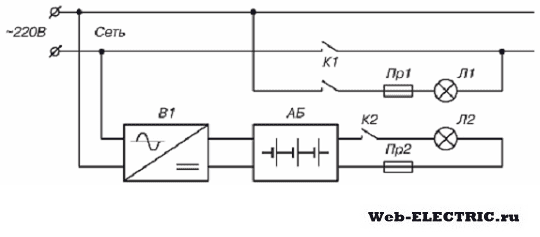
So, the diagram:
Let's look at how it works:
The backup power source for the automatic emergency lighting is a 12 Volt battery. When there is voltage in the network, it (the battery) is constantly recharged: for this, a simple charger is used on the elements: a transformer, a diode bridge, and a stabilizer on the LM317 chip.
Moreover, a circuit is introduced into the control circuit of the microcircuit that prevents overcharging of the battery on the transistor.
This same power source (transformer and diode bridge) also serves as a power source for a landline telephone, night lighting LEDs and an ambient light sensor: for this purpose, another stabilizer is used on the K142EN5 chip (the usual so-called).
Relay P1 must be normally closed: that is, when it is off, its contacts must close.
When there is voltage in the mains: relay P1 is turned on, its contacts are open, the battery is in recharging mode, power from the diode bridge is supplied through the diode to the 5-Volt KRENK and from there to the photo relay and telephone set.
If there is a power outage: relay P1 will turn off, and power to the KRENK will come from the battery.
But the photo relay will work in the same mode: it will turn on only when natural light decreases
Emergency lighting schemes for different premises differ significantly. This depends on their size, the power of the emergency lighting system and, in fact, the requirements for the lighting itself. Therefore, at the moment there is a rich variety of schemes that allow solving problems of any complexity and with varying levels of investment.
Where should emergency lighting be installed, and what are the requirements for it?
Before talking about schemes and areas of application, let's look at the questions of where this emergency lighting should be. In addition, you should definitely understand the issue of standards for emergency lighting. All this is spelled out in detail in SNiP 05/23/95, and in our article we will only try to explain all these requirements in simple language.
Premises that must have emergency lighting
Emergency lighting is divided into two main types - evacuation and safety lighting. The first should ensure the safe movement of people in emergency situations, and the second should ensure a minimum level of illumination in areas where critical infrastructure is managed.
|
|
Based on this, emergency lighting must be implemented in heating points, electrical stations and substations, water supply and wastewater pumping stations, ventilation rooms and control points for air conditioning systems, if disruption of the operation of these facilities can lead to the shutdown of industrial or residential areas. |
|
|
It is mandatory that safety lighting be installed in areas where interruption of work could lead to explosions or fires. And even if stopping work in a certain room leads to long-term downtime of the entire technological chain, then it is necessary to equip them with safety lighting. |
|
|
Evacuation lighting should be available in all industrial buildings without natural light. In addition, it must be installed in all main passages if more than 50 people will move along them during evacuation. For auxiliary premises this norm is lower and amounts to 100 people. |
|
|
It is mandatory that evacuation lighting should be in a building with 6 or more floors, in medical and children's institutions. For dormitories, it should be equipped when the length of the corridors is more than 25 meters, or when more than 50 people live in it. |
|
|
In retail premises, the norm for installing such lighting is an area of 90 m2. In addition, evacuation lighting should be installed above the cash registers |
|
|
This type of emergency lighting should be created in sports, bathing, medical and preventive premises, repair shops, locker rooms, kitchens and other facilities of public buildings. It should be installed in assembly and conference halls with more than 100 seats. |


Emergency lighting requirements
Now let's talk about the requirements that regulations impose on emergency lighting. Moreover, depending on the type of emergency lighting, these requirements differ quite strikingly.

- Let's start our conversation with security coverage. As the instructions say, it should provide a minimum illumination of 5% of the normal minimum illumination. For example, we have a room in which the minimum illumination level is 200 lux. Accordingly, the minimum standard of security lighting should be at least 10 lux.

Note! In all cases, the minimum standard of security lighting should be at least 2 lux inside buildings. On the territory of the enterprise this norm is 1 lux.
- But with evacuation lighting, everything is a little more complicated. And this is not due to the minimum illumination standard, which for indoor areas is 0.5 lux, and for outdoor areas 0.2 lux, but with the rules for placing the lanterns themselves.
- Evacuation lighting should be located every 25 meters along the evacuation route. In addition, they must be at every turn and in front of every door.
- But the fact is that the standards prohibit a difference between the most and least illuminated areas of more than 1 to 40. This requirement often determines the use of lamps with the most diffused light, as well as a reduction in the distances between lamps.

- Separately, it is worth noting the lamps that should be used for emergency lighting systems. The fact is that regulatory documents prohibit the use of sodium, xenon, DRL and metal halide lamps, which take a long time to light up and can go out during operation.
Schemes for emergency lighting systems
Having an idea of the types and requirements for these lighting systems, we can talk about the circuits themselves. At the moment, a fairly large number of them have been proposed, and there are schemes both for a fairly large lighting network and for systems with a small number of lamps.
Emergency lighting power supply circuit from a second power source
The simplest diagram of an emergency lighting network from a technical point of view is that it is powered by an independent power supply. But let’s be honest, such a scheme is used quite rarely due to the fact that economic feasibility interferes with purely technical conditions.
The cost of another connection to the electrical network in many cases forces one to abandon this option. Meanwhile, it is one of the most convenient.
- The essence of this option comes down to the following. A room or group of rooms has one main power supply from a public electrical network. To connect emergency lighting, another supply line is supplied to the room. The main condition for this line is that it is powered from another source - this may be another bus system at the supply substation or another substation altogether.
- The backup power line may have a lower power rating. The main thing is that it is enough to power the entire emergency lighting network and other electrical equipment connected to it.
In the future, there are two options:
- Option number one- this is when all electrical equipment in the room is powered from the main line in normal mode. When the voltage on the main line disappears, the emergency lighting network begins to receive power from the backup line.
- Second option- this is when the emergency lighting lines are constantly powered from a backup line, and the emergency lighting network operates constantly, regardless of the presence of the main power supply. In this case, it is necessary to be able to connect the emergency lighting network to the main line to carry out repairs and troubleshoot problems on the backup line.
Powered by diesel generator
But as we have already mentioned, the price of the option with connecting two independent lines is not always within reasonable limits. Therefore, sometimes it’s easier to do it on your own and create an autonomous power source yourself. This can be a gasoline, gas or diesel generator.
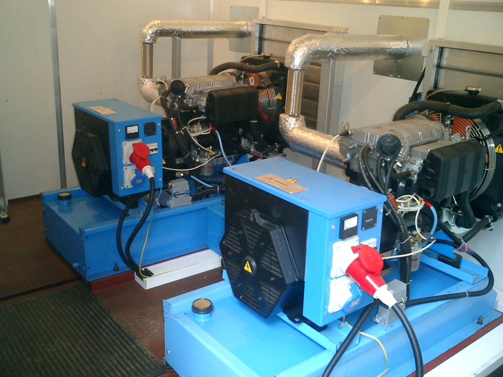
- Such a generator can be installed in a special room. In addition, it will require a fuel storage container. Usually its volume is taken to be sufficient for an hour of generator operation, unless otherwise provided by the requirements for your premises. Connecting the generator will allow fuel to be supplied from the tank directly to the engine. The autostart system will allow you to turn on the generator without your participation.
- So, for this circuit, under normal conditions, all power is taken from the main line. When the voltage on it disappears, the diesel generator is switched on. It supplies power to the emergency lighting network.
- But there are a few buts here. In order to start the generator, you need special automation, and it is powered from the electrical network. But if the power has already disappeared, how will the automation work?

- There are several options for this. The simplest and cheapest option is to use a special capacitor, which can easily store a sufficient amount of electricity for a single turn-on command.
- But if the generator does not turn on the first time, then it can only be turned on manually. This is not very convenient, especially in emergency situations. Therefore, they often additionally purchase a small battery that will ensure the operation of the emergency automation system.
Power schemes using batteries
In general, the option using batteries is one of the most common. After all, implementing it yourself is quite simple and, in some cases, it is a little cheaper.

- Electric energy batteries allow you to accumulate and store energy. But if alternating electric current flows in our network, then the battery can only work with direct current. In this regard, they require the installation of special devices - inverters, which convert alternating current into direct current and vice versa.

There are several options for schemes using batteries to power the emergency network:
- Option number one– this is when the emergency lighting network is powered by an inverter, and a battery is connected to the same network. In normal mode, the inverter is connected to AC power. Its DC output circuits are connected to the DC switchboard (DCB). During normal operation, it powers all luminaires connected to the emergency lighting network and recharges the battery, compensating for self-discharge of the battery.
When the AC voltage disappears, the inverter stops working. All power to the emergency lighting network is supplied by the battery, which must ensure its operation for at least half an hour or another period of time.

Note! For all schemes when using a battery, its capacity must be selected in accordance with the total power consumption. In this case, the battery itself must be periodically subjected to control charges and discharges to check it.
- Second option- this is when the inverter is connected directly to the battery. All emergency lighting is powered by battery. The inverter constantly recharges the battery, which ensures its constant capacity. When the AC power is turned off, the inverter turns off and the emergency network is powered only by the battery, as in the video.
- Third option- this is when the inverter is connected to the battery, and the emergency lighting is powered by the battery, but it is constantly turned off. Only when the main source voltage disappears is the emergency lighting network disconnected from the main source and connected to battery power.

But the fact is that only certain types of lamps capable of operating on direct current can be powered from the above circuits. But motors and some types of lamps cannot operate on direct current. To power them, it is possible to install an additional inverter in the circuit of the second and third options. Only now it will convert direct current into alternating current. As a result, we get alternating current at the output from the battery.
Lamps with built-in battery
But such a complex circuit is not always necessary, and emergency lighting should be powered specifically from individual lighting groups. For small buildings, for which up to 50 lamps are sufficient, it is much more advisable to use lamps with a built-in battery.

- The essence of this scheme is as follows. You purchase special lamps with a built-in battery. This lamp already has a built-in inverter that recharges the battery. Under normal conditions, it is powered by AC power. When the power goes out, it disconnects from the AC mains and starts running on battery power. Its operating time usually does not exceed 3 hours.
- Lamps can be of different types. Some are constantly running on battery power and the inverter recharges it. Others are constantly running on AC power, and the battery only turns on in emergency modes.
- There are luminaires with one or more lamps powered by AC power and one or more lamps powered by a battery. This allows you to choose a lamp in exact accordance with your wishes and requirements.

- Such lamps can also be divided into groups according to the location of the battery installation. Some have a remote battery that is hidden under suspended ceilings, others have a battery that is built into the lamp itself.
- The warranty period for such lamps is usually 10-15 years. But in reality, this time is limited by the battery life. Therefore, after replacing it with a new one, the lamp can work for a longer period.
Conclusion
Emergency lighting and its connection diagram have many options. However, it is not at all necessary to use only one of them. Options with a combination of several different types on one object are quite possible. This allows for optimal power supply to the entire emergency network and minimal capital investment.
min.
Electricity has become such an integral part of our lives that when the lights are turned off, life seems to freeze, things don’t get done, and darkness reigns in the house. To prevent power outages from dictating your life rules, we will tell you how to do it for your home, garage, cottage, and even tent. Of course, for people ignorant of electrical engineering, this idea may seem not only incomprehensible, but also risky, but, as you know, everything ingenious is simple!
Undoubtedly, rushing headlong into the maelstrom of electricity without minimal knowledge is absurd, to say the least. Therefore, first you should learn the basics and all the subtleties of emergency lighting.
Features of emergency lighting
Emergency lighting is independent of the main network and is designed to create sufficient visualization for people to freely navigate in the dark when the main lighting is turned off.

According to the PUE regulations, emergency lighting must have white light and a minimum permissible illumination of 1 lux.
To provide emergency lighting, you can use any light sources: incandescent lamps, fluorescent lamps.

But the most popular today are 12-volt LEDsLED. They provide enough light and also significantly save battery energy reserves, which allows you to use such lighting longer.
When planning to install backup light sources at home, you should also take note of the following rules:
At least two lamps should be installed in one room, so that if one fails, the second one will take over the lighting task.
Lamps should be installed so that they can provide sufficient visualization for orientation in a dark room. It is best to install lamps in the center of the room, as well as in places of increased risk of injury and importance: stairs, doorways, passages, turns, lighting control panel, exits.

You should carefully consider the emergency lighting scheme, as well as the method of its control: manual or remote. In the case of the manual control method, you need to provide easy access to the switch so that you can easily find the lighting power source in the dark.

Create your own emergency lightingfrom batteryIn principle, any amateur electrician can do it at home if he has detailed instructions at hand.
First you need to select the necessary lamps, the voltage of which will not exceed 12 volts. In fact, this is the main requirement for emergency light sources.
Each emergency lighting system must contain autonomous power sources (batteries, generators), lighting devices and other elements, for example, a relay, power supply, remote control device.
Backup and central lighting are installed parallel to each other. They cannot be combined!
Also, the laying of emergency and main system lines must be done separately. This will greatly simplify testing the functionality of lighting systems.
In the case of an automatic system for switching main lighting to backup lighting, both networks are connected to the switch.
Here it is extremely important to achieve timely switching, which is why it is better to entrust the assembly of such a lighting system to professionals.

Today, backup lighting systems are increasingly equipped with remote control devices, such as, for example, TELEMANDO, which is ideal for 12-volt luminaires such asLED. This device contributes to economical battery consumption of the backup power supply, and also helps to eliminate problems in the network, if any.
In addition, the device itself has built-in batteries and a two-position return switch. Typically, the remote control device is mounted in distribution panels on DIN rails.

DIY emergency lighting, diagram
In the world of electrical engineering, you can find many backup lighting schemes of various types of complexity. Let's look at a standard scheme in which the main and backup power supplies and separating devices for switching the system from normal mode to emergency mode will be used.
For this assembly of such a lighting system, the following elements will be required:
- Light bulbs (2 pcs.), one of which will work in normal mode, and the other will turn on in emergency situations.
- Battery to provide power to the lamp in emergency mode.
- Fuse box.
- Relay contacts.
- Electric current rectifier.
In normal mode, the main lamp is connected to the network using a relay contact. The backup power supply is connected to the electric current rectifier and remains in a state of continuous recharging.
When there is a power outage, the second relay contact automatically closes and the battery then begins to supply power to the backup light source.
This emergency lighting scheme involves laying two parallel power networks, where one operates the main lighting element, and the second operates exclusively as a reserve. For basic lighting, you can take lamps of any type, while for emergency lighting you should choose low-power lighting sources.
A simpler emergency lighting system is shown in the video:
The advent of LEDs has greatly simplified the assembly of emergency lighting systems. It is on the basis of these flashlights that numerous simple circuits are written. We will try to assemble just such a system based on a battery and an LED strip with our own hands. The control of such illumination is manual, and accordingly the assembly scheme is the most primitive.
Inventory
- 12-volt 4 Ah portable battery, or larger capacity if you want to extend the light's operating time.
- LED strip – 2 m. You can take a shorter piece of strip, so the battery consumption will be less and the backup light will work longer. In principle, instead of tape, you can take any other lighting sources 12V, in particular LED modules.

- We will also need contact wires with connectors to connect the battery to the diodes.

The first thing we need to do is connect the contact wires to the LED strip. If you are using the entire tape with the original wires extending from it, then simply connect the contact wire to the wires of the tape color to color. Also connect the wire with the connector to the battery according to the polarities.
If you use a cut piece of tape, then the contact wires should be soldered to the contacts of the tape: red to the “+” contact and black to the “-” contact.
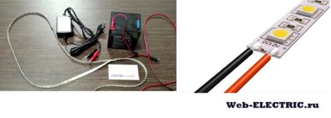
After the contact wires are connected, connect the tape connector to the battery connector. LEDs provide enough illumination. Such a system can be used not only as emergency lighting, but also as an illuminator in natural conditions (hiking, fishing, summer cottage).

LED lamps rechargeable
When the lights go out, the first salvation from the darkness in the house is a flashlight or a candle. There is little light from them, and such methods only work for a very short time, unless, of course, you have extensive supplies of candles and batteries.
Today, online stores are literally full of different models of LED lamps with rechargeable batteries that can provide enough light for several hours of continuous operation. Such lamps have several operating modes, they are mobile, durable and affordable.

Battery powered light bulbs
Rechargeable lamps, which look like ordinary light bulbs with a base, are also gaining popularity today. Such light sources have 2 operating modes: storage and emergency and are equipped with a convenient switch. In normal mode, the light bulb shines normally, but when the light is turned off, you can switch the light to standby mode using the control panel. The cost of one such light bulb reaches 500 rubles. And this is the simplest emergency lighting option today.

Photoluminescent evacuation system
Many enterprises are increasingly using photoluminescent lighting systems. For this purpose, panels, signs, plans and other elements treated with phosphor are used, or the phosphor is embedded in the material itself from which the indicating elements are made.

The phosphor is capable of accumulating light during the day, and in the dark it releases the accumulated energy in the form of a green glow. However, the disadvantage of such illumination is that it will always shine at night and cannot be turned off.
Modern technologies are designed to make our lives easier, and thanks to their development, an event such as a power outage is not capable of making us defenseless, like blind kittens, becauseDIY emergency lightingAnyone can do it at home, in the country or in the garage.
Preference should be given to electronic transformers in a metal case, since they heat up during operation, and plastic does not dissipate heat well.
In the bathroom, jacuzzi, kitchen or for lighting, only lamps with 12 V lamps can be installed - this is a safety requirement. Moreover, luminaires with 12 V lamps can be retrofitted for emergency lighting in case of any problems with the power supply. But more on that a little later.
Summarize.
So, although halogen lamps have high light output, they become very hot during operation. The electronic transformer also gets hot. The energy consumption of halogen lamps is quite significant, and over time, you may want to replace halogen lamps with LED lamps.
LED lamps with comparable brightness consume 10-15 times less electricity. They are available in the same housings as halogen lamps. LED lamps, like halogen lamps, have different operating voltages: 12 V and 220 V.
Preference should be given to 12 V LED lamps, since 220 V lamps have a simple conversion circuit with a quenching capacitor, which, when the lamp is turned on (until the capacitor is charged), passes all the mains voltage to the LEDs. Such a lamp, if turned on frequently, will not be able to work out even half of the resource declared by the manufacturer (about 30,000 hours).
Another advantage of LED lamps with an operating voltage of 12 V is that such lamps are available in different colors: red, green, yellow and blue. Using these lamps for illumination or at home, you can create unusual romantic lighting.
The color of the glow (shades of white) for conventional LED lamps is different: from white with a yellow tint to white with a bluish tint (cool white). It all depends on the so-called color temperature, which is measured in degrees Kelvin.
This temperature is indicated both on the lamp itself and on the packaging. The most optimal color for everyday use is white with yellow honey fungus. This color corresponds to a temperature of approximately 3000 K. Pure white (4500 K) and cool white (6000 K) can cause fatigue and irritation, so lamps with this color temperature are not recommended for use in household lighting fixtures.
The luminous flux of LED lamps varies widely - from 100 lm to 450 lm and depends on the number of LEDs, as well as their type. Lamps with bright SMD LEDs are more common. In the last few years, lamps with super-bright LEDs have appeared.
The number of LEDs in 12 V lamps is a multiple of 3 (3, 9, 12, 15, 18, etc.). The power consumed by such lamps does not exceed 3.5 W and most often lies in the range of 1.5-2 W. Thus, 50-75 LED lamps can be connected to one 100 W transformer.
However, not all so simple. If you replace all the halogen lamps with LED lamps and turn on the lights, you will be disappointed - the lamps will not glow (photo 2). The reason for this strange behavior is that the electronic transformer implements current feedback, and to run the transformer requires a load that LED lamps cannot provide.
Therefore, after replacing halogen lamps with LED lamps, you will have to change the electronic transformer - this is what both the electrician and the sales assistant in the store will advise. Converters (current sources) for powering LED lamps are almost 10 times more expensive than electronic transformers with comparable power and differ from them in size (photo 3).
But there is one fairly simple way to restore the functionality of an electronic transformer and power LED lamps from it: it is enough to connect one halogen lamp with a power of about 15 W in parallel with the LED lamps. That's all! No intervention is required in the electronic circuit of the transformer itself.
Do-it-yourself emergency lighting (in case of a power outage) - diagrams
And now about how to provide emergency lighting when the mains power is cut off. The simplest method - connecting a battery in parallel to the transformer - will not lead to the desired results, since the battery will simply short-circuit through the electronic transformer. To avoid a short circuit, some kind of decoupling must be installed. In our case, diodes will serve as such decoupling.
The current consumed by one LED lamp is in the range of 0.1-0.15 A, the supply voltage is 12 V. The frequency with which the electronic transformer operates is 35 kHz. Almost any high-frequency diode with a reverse voltage of at least 40 V and a forward current of 0.2 A or higher is suitable as such a barrier element - for example, 1N5819, BY398 or SF11-SF16 or others with similar characteristics.
Unfortunately, this list does not include domestic diodes, since they are very rarely found on sale, and their price is incomparably high.
Diodes have a stripe on the body corresponding to the negative terminal (photo 4). The diodes must be turned on so that the negative from the electronic transformer and the negative from the battery are connected at a common point.
Diodes can be placed directly on the terminal block (photo 5). Power from the battery is not supplied to all lamps, but to half of their total number. Such moderate illumination will not create any particular inconvenience and will allow rational use of battery power.
It is permissible to use only sealed gel acid batteries indoors (photo 6). If a car battery is selected, it should be placed in a storage area, such as a basement, and maintained at the temperature and humidity recommended by the battery manufacturer. Of course, it should be recharged periodically to ensure it is always in working order.
Two cables should be laid to the part of the luminaires that will play the role of emergency ones: one cable supplies power from a transformer, the other from a battery (Fig. 1). While the electronic transformer is operating, due to reverse bias, the diode coming from the battery is closed.
But as soon as the mains voltage disappears, the diode connected to the battery opens, and some of the lamps continue to work.
Such a simple circuit has one drawback: if you turn off the lights, power to the lamps will come from the battery. That is why another switch is required - from the battery (Fig. 2).
Lighting can be made completely autonomous by installing LED lamps and connecting them to a battery.
The battery can be charged from a windmill, solar battery or gasoline generator. For comfortable lighting of one room, 5 to 10 LED lamps are needed.
Thus, to illuminate buildings located far from power lines, for example, country houses, a power of about 30 W will be required. It will be provided during the day by one car battery with a capacity of 55 Ah.
Photo for article: Necessary equipment and emergency lighting schemes
The electronic transformer, with its small dimensions (63x42x28 mm) and weight (less than 100 g), has a power of more than 100 W.
- When LED lamps are connected to an electronic transformer, they do not light up because the transformer does not switch to operating mode.
- Current source for powering LED lamps.
- The negative terminal of the diode is marked with a solid stripe on the housing.
- Connecting diodes to the lamp.
- Rice. 1. Isolation of battery and electronic transformer.
- Rice. 2. General diagram of emergency lighting.
L1 – halogen lamp 15-30 W. LED 1 – LEDNN – LED lamps for main lighting. LED2 – LED11 – LED emergency lighting lamps. B1.B2 - mains and battery switches - respectively.
 COB LED lamp Chip 220 V smart ic no need driver...
It often happens that there is no electricity for various reasons and there is no lighting. Then we use candles, flashlights, and, at worst, kerosene lamps. Candles smoke and are a fire hazard; a flashlight has a directional light and does not always have a long glow life. I suggest making an alternative.
This design will use available components, mainly from old computer power supplies. The schematic diagram of the device is shown below:
The power source for the circuit is a 12V battery with a capacity of at least one and a half ampere hours. The role of the light source will be performed by a “housekeeper” light bulb with a power of 8–15 watts.
Components borrowed from a computer power supply:
– pulse transformer;
– PWM controller TL494;
– high-voltage capacitors (C3, C4);
– high-frequency diodes (VD1, VD2);
The remaining components must be purchased. All components are mounted on a single-sided printed circuit board measuring 50mm. at 54mm. (minimum dimensions, excluding space for fasteners).

The printed circuit board file was made in the Sprint-Layout 6.0 (5.0) program and is attached at the end of the article, in the archive. The file shows a view of the board from the components side.
The output transistors must be installed on a heat sink, a radiator, for example, from an old computer processor. A correctly assembled device does not require adjustment and will work immediately. When turned on, the board consumes about 1.5 amperes for a short time to charge the capacitors, then at the end of the charge it consumes 0.75 amperes per hour.
Since there is no housing yet, I did not screw the radiator on for testing.


The light comes on almost immediately, and shines as if from a regular electrical outlet. The light bulb can be placed either next to the body or on the ceiling as an alternative lamp.
ATTENTION: at the output of the circuit we will get a constant voltage with an amplitude of 220 volts, BE CAREFUL!!!
Files: