An oscilloscope from an old TV. Turning a TV into an oscilloscope Television oscilloscope
The set-top box, the diagram of which is shown in Figure 1, turns any TV into an oscilloscope with a large screen. You can observe low-frequency oscillations on it, and with the help of a sweep frequency generator (SWG) you can visually tune the IF amplifiers of radio receivers.
The set-top box can be considered as a miniature television transmitter. Despite the relative simplicity of the circuit, this transmitter generates a complete television signal, which differs from the standard signal only in the absence of equalizing pulses.
Schematic diagram
Frame sync pulses are generated from an alternating sinusoidal voltage by the limiting amplifier T1, the differentiating circuit R8C4 and the threshold amplifier T4. Their duration is about 1.9 ms.
The blocking generator on transistor T5 generates horizontal sync pulses. These are not the main pulses of the blocking generator, but surges of the collector voltage that occur immediately after the main ones. A DZ isolation diode is connected between the collectors of transistors T4 and T5.
At the moment of generation of the main pulse, the collector of transistor T4 is closed to the chassis through the open transistor T5 and the DZ diode. As a result, insets appear in the vertical sync pulses, which, as required, precede the horizontal sync pulses.
The windings of the transformer Tr1 of the blocking generator are wound on a toroidal core made of oxyfer (ts = 1000). The outer diameter of the core is 10 mm, thickness 2 mm. Windings I and III contain up to 100 turns, and Winding II - 30 turns of PELSHO 0.1 wire.
At the beginning of the horizontal scanning period, the voltage pulse of the blocking generator quickly charges capacitor C5 through diode D2. During the rest of the period it is slowly discharged through resistor R6. The resulting sawtooth voltage is supplied to the base of transistor T2. Here it is added to the oscilloscope voltage.
A three-stage amplifier (T2, T3, TB), due to its large gain coefficient (50,000-100,000), operates practically in a relay mode, characterized by a certain response threshold.
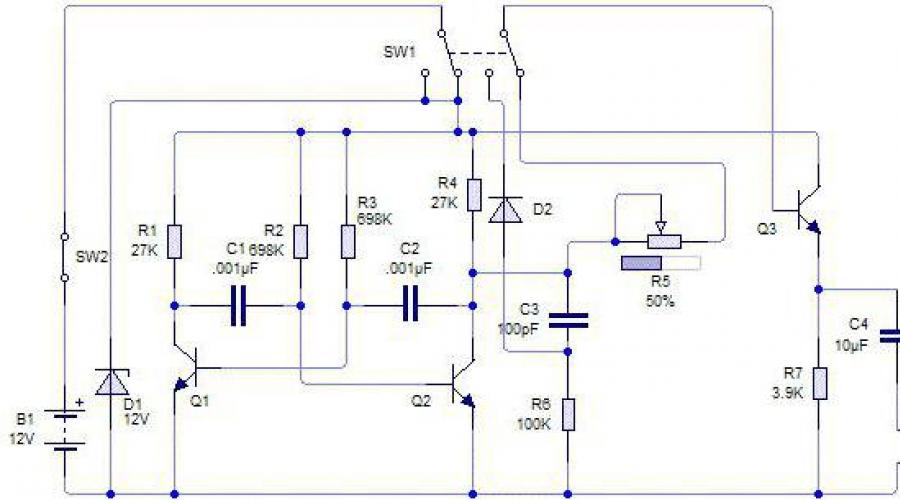
Rice. 1. Schematic diagram of a set-top box that turns a TV into an oscilloscope:
a — block diagram: L—block for generating frame synchronization pulses; B — line synchronization pulse generator; C - blocking generator; D—block that converts voltage into video pulses; E - VHF generator with amplitude modulation; “Input” - terminals to which the voltage being tested is supplied: 6 - circuit diagram.
The attachment parameters are chosen such that in the absence of the voltage being tested, the center line is in the center of the screen. If necessary, the image on the screen can be shifted in one direction or another by changing the resistance of resistor R3.
To improve the clarity of the line image on the TV screen, the amplifier (T2, T3, Tb) is covered by positive feedback from the collector of transistor T3 to the base of transistor T2 through capacitor Sb. This significantly increases the gain in the high frequency region and, therefore, increases the slope of the front of the output pulses. Visually, this manifests itself in an increased sharpness of the transition from white to black.
Frame, line and video pulses are added at the input of the emitter follower T1, which is the modulation amplifier of the VHF generator T8.
The latter is assembled according to a three-point capacitive circuit. The generation frequency must be chosen equal to the carrier frequency of the image of a free television channel. Otherwise, the set-top box may interfere with the operation of neighboring TVs.
The required generation frequencies can be achieved by selecting the number of turns of coil L1. When tuning to the second television channel (59.25 MHz), coil L1 contains 5 turns of PEV 0.6 wire, coil diameter 9 mm.
The modulated RF voltage is supplied to the output of the set-top box through a divider R18 - R19, which reduces the voltage to 3 mV to avoid overloading the RF path of the TV. The output of the set-top box is connected with a coaxial cable or twisted double wire to the antenna input of the TV.
Construction and setup
All parts of the set-top box, with the exception of the VHF generator, can be placed on the circuit board in any order. The parts related to the VHF generator (C11 - C15, L1, T8) must have short leads, be connected to each other by short conductors, and, in addition, they should be grouped in one place.
No shielding of the console is required. After turning it on, you must, as usual, adjust the TV using the adjustment knobs (frame rate, line frequency, contrast).
If the pulse frequency of the blocking generator of the set-top box does not lie in the range of adjusting the line frequency of the TV, it is necessary to enter it into this range by changing the resistance of resistor R14 within small limits.
It should be noted that the synchronization of the TV scans from the set-top box is usually very stable, so poor synchronization when setting up the set-top box indicates some kind of installation error. To achieve precise tuning of the VHF generator of the set-top box to the selected television channel, you have to stretch or compress the turns of the winding of coil L1, i.e. change the winding pitch. When set correctly, the line on the screen is sharply defined.
The parameters of the set-top box are selected so that the largest scope of the image on the TV screen corresponds to an input voltage of about 0.3 V. The sensitivity of the set-top box can be adjusted by changing the resistance of resistor R2.
To check the sensitivity of the set-top box, an alternating voltage of a known magnitude is supplied to its input either from a power source with a voltage of 6 V, a frequency of 50 Hz through a divider, or from a sound generator.
If desired, the input impedance and sensitivity of the set-top box can be significantly increased by connecting to it a conventional low-frequency amplifier with an emitter follower at the input.
The set-top box turns any TV into an oscilloscope with a large screen. You can observe low-frequency oscillations on it, and with the help of a sweep frequency generator (MSG) you can visually tune the IF amplifiers of radio receivers. The set-top box can be considered as a miniature television transmitter. Despite the relatively simple circuit, this transmitter produces a complete television signal, which differs from the standard one only in the absence of equalizing pulses.
Frame sync pulses are generated from the reference sinusoidal voltage by the limiting amplifier VT1, the differentiating circuit R8C4 and the threshold amplifier on VT4. Their duration is about 1.9 ms. The blocking generator (on transistor VT5) generates horizontal sync pulses. These are not the main pulses of the blocking generator, but surges of the collector voltage that occur immediately after the main ones. A diode VD3 is connected between the collectors of transistors VT4 and VT5. At the moment the main pulse is generated, the collector of transistor VT4 is closed to the chassis through an open transistor VT5 and diode VD3. As a result, insets appear in the vertical sync pulses, which, as required, precede the horizontal sync pulses. The windings of the blocking generator transformer VT1 are wound on a toroidal core made of oxypherite (F-1000). The outer diameter of the core is 10 mm, thickness 2 mm. Windings I and III each contain 100 turns, and winding II contains 30 turns of PELSHO o0.1 wire. At the beginning of the horizontal scanning period, the voltage pulse of the blocking generator quickly charges capacitor C6 through the diode VD2. During the rest of the period it is slowly discharged through resistor R6. The resulting sawtooth voltage is supplied to the base of transistor VT2. Here it is added to the input voltage. The three-stage amplifier, due to its high gain (50,000-100,000), operates practically in relay mode, characterized by a certain response threshold. The attachment parameters are chosen such that in the absence of the voltage being tested, the center line is in the center of the screen. If necessary, the image on the screen can be shifted in one direction or another by changing the resistance of resistor R3. To improve the clarity of the line image on the TV screen, the amplifier (VT2, VT3, VT6) is covered by positive feedback from the collector of transistor VT3 to the base of transistor VT2 through capacitor C5. This significantly increases the gain in the high frequency region and therefore increases the slope of the output pulses. Visually, this manifests itself in an increased sharpness of the transition from white to black. Frame, line and video pulses are added at the input of the emitter follower VT7, which is the modulation amplifier of the VHF generator VT8. The latter is assembled according to a three-point capacitive circuit. The generation frequency must be chosen equal to the carrier frequency of the image of a free television channel. Otherwise, the set-top box may interfere with the operation of neighboring TVs. The required generation frequencies can be obtained by selecting the number of turns of coil L1.
When tuning to the second television channel (59.25 MHz), coil L1 contains 5 turns of PEV 0.6 wire, coil diameter 9 mm. The modulated RF voltage is supplied to the output of the set-top box through a divider R18-R19, which reduces the voltage to 3 mV to avoid overloading the RF path of the TV. The output of the set-top box is connected with a coaxial cable or twisted double wire to the antenna input of the TV.
Construction and setup. All parts of the set-top box, with the exception of the VHF generator, can be placed on the circuit board in any order. Parts related to the VHF generator (SP-S15, L1, VT8) must have short leads, connect them together with short conductors and group them in one place. No shielding of the set-top box is required. If the pulse frequency of the block generator does not lie in the line frequency range of the TV, it is necessary to enter it into this range by changing the resistance of resistor R14 within small limits. It should be noted that the synchronization of TV scans from the set-top box is usually very stable, so poor synchronization when setting up the set-top box indicates some kind of installation error. To achieve precise tuning of the VHF generator of the set-top box to the selected television channel, you have to stretch or compress the turns of the winding of the L1 coil, i.e. change the winding pitch. When set correctly, the line on the screen is sharply defined. The parameters of the set-top box are selected so that the largest image size on the TV screen corresponds to an input voltage of about 0.3 V. The sensitivity of the set-top box can be adjusted by changing the resistance of resistor R2. To test sensitivity, an alternating voltage of a known magnitude or from a sound generator is supplied to the input.
Until recently, many types of UHF selector set-top boxes were produced, designed to receive television signals on any of the 21 UHF channels (from 21 to 41) and convert them into VHF signals (1st and 2nd channel) . The absence of a UHF unit in televisions of previous generations forced many to purchase consoles DMV. In Vitebsk, a transmitter on channel 48 was recently turned on. To expand the received range to the 59th channel, I propose the simplest modification of the Uman selector set-top box and similar ones with a range of 21 ... 41 channels. The improvement consists of increasing the tuning voltage (UH) of the vari-caps to 26 V (instead of 18 V). To do this, you need to break the connection between resistors R2 and R3 of the stabilization unit and apply pin 3 of resistor R2 to point R1 (Fig. 1). You can do this by switching through a toggle switch (Fig. 2) - then the range of 21...41 channels is preserved. Puc.2After this, tune to the 48th channel (or another of this order) as usual. This modification is done in a similar way on other types of UHF selector set-top boxes, designed to receive 21...41 channels. Their schemes are practically unified. V. REZKOV, 210032, Vitebsk, Chkalova st., 30/1 - 58. ...
For the circuit "OSCILLOGRAPHIC ATTACHMENT FOR TV"
Measuring equipment OSCILLOGRAPHIC ATTACHMENT K Eng. V. KRAPIVNIKOVDescriptions of oscillographic attachments for TV have already been published on the pages of the magazine ("Radio", 1959, No. 1; 1965, No. 8, etc.). However, unlike them, the proposed set-top box does not require intervention in the TV circuit (it is connected to the TV antenna socket). Together with a sweep frequency generator, it can be used to set up IF amplifiers for radio receivers. The set-top box (Fig. 1 and 2) can be considered as a miniature television transmitter. Despite the relative simplicity of the circuit, a complete television signal is generated in this transmitter, which differs from the standard signal only in the absence of equalizing pulses. Figure 1 Frame synchronization pulses are formed from an alternating sinusoidal voltage by a limiting amplifier (T1), a differentiating circuit R8C4 and a threshold amplifier (T1). A simple thermostat based on a triac. Their duration is approximately 1.9 ms. Puc.2The blocking generator on the transistor Гз generates horizontal sync pulses. These are not the main pulses of the blocking generator, but surges of the collector voltage that occur immediately after the main ones. A diode D3 is connected between the collectors of transistors T4 and T5. At the moment the main pulse is generated, the collector of transistor T4 is closed to the chassis through the open transistor T5 and diode D3. As a result, insets appear in the vertical sync pulses, which, as required, precede the horizontal sync pulses. The windings of the transformer Tr1 of the blocking generator are wound on a toroidal core made of oxyphere (H=1000). The outer diameter of the core is 10 mm, a. thickness 2 mm. Windings I and III contain...
For the "MODULATOR" circuit
Amateur radio equipment units MODULATORN. Martynyuk 225860, Brest region, Kobrinul. Yuzhnaya, 18 The modulator-transmitter is designed to interface a VCR or video camera with a TV at high frequency. Most VCRs have a high frequency output, but some models of VCRs and TVs have an intermediate sound frequency does not comply with our standard (6.5 MHz), therefore, when connected via high frequency, there is no sound on the TV. Also, most modulators operate in the UHF range, which requires an ACS unit in the TV. This modulator-transmitter generates a complete television signal at a frequency of 1...3 MB channels. The intermediate frequency of the sound is set by potentiometer R6. The modulator can be connected to TV shielded cable or over the air (like gaming consoles type "Dandy") The image carrier frequency generator is assembled on transistor VT3, and the sound carrier frequency generator is assembled on transistors VT1, VT2. Transistor VT3 converts low-frequency video and audio signals into radio frequency signals. The LI coil is frameless, wound on a mandrel with a diameter of 6 mm with 0.8 PEL wire and contains 8 turns. L2 - 2 turns with PEL wire 0.4 over L1. Potentiometer R6 sets the required intermediate frequency. The modulator-transmitter can also be used in conjunction with a personal computer. Amateur Radio 9/97, p.5....
For the circuit "A circuit that provides scanning along the diagonal axis of any oscilloscope"
For the radio amateur designer A circuit that provides scanning along the diagonal axis of any Lanz, Stanford University (Stanford, California) A circuit has been developed that allows one to obtain a diagonal deviation regardless of the existing vertical and horizontal deviation channels. As a result, with the help of any oscilloscope Instead of the usual two-dimensional oscillograms in the X-Y plane, you can actually obtain a three-dimensional image. The resulting three-axis display with X, Y, Z axes creates an amazing 3D image result without any modification to the oscilloscope. The new device allows you to study three-parameter curves and three-frequency Lissajous figures, obtain three-dimensional images of signs, and can also be used in various visual indicators. For diagonal deflection, the diagonal deflection input signal is simultaneously fed to the inputs of vertical and horizontal deflection amplifiers. The result is the well-known Lissajous figure for common-mode signals, namely a line at an angle of 45°. Op-amps A1 and A2 decouple the diagonal signal input from the vertical and horizontal signal inputs, and op-amps A3 and A4 sum the components of the diagonal signal with the vertical and horizontal signal inputs, respectively. The gains of operational amplifiers A1 and A2 are adjusted in a certain way, since the angle of inclination of the diagonal axis is directly proportional to their ratio. By adjusting the three input circuits, separate sensitivity control of all three channels is provided. FIG. 1. Four operational amplifiers provide diagonal deflection of the beam and create a depth result on the screen of a conventional oscilloscope...
For the scheme "ATTACHMENT-GKCH FOR RANGES 300...900 and 800...1950 MHz"
Measuring equipment ATTACHMENT-GKCH FOR RANGES 300...900 and 800...1950 MHz Adjustment of radio-electronic equipment with visual display of amplitude-frequency characteristics is constantly of great interest among radio amateurs and specialists, as it allows you to quickly see on the screen of the measuring device the results of the influence when changing what -parameter or element of the customized product. The only drawback of this control method is the relatively high price(s) of industrial samples of frequency response meters. But radio amateurs have found a worthy solution here too - the creation of simple attachments for the already familiar oscilloscope. In this case, the frequency response itself does not play a special role. In the magazine "Radio" 1994, No. 1, p. 26, a description was given for adjusting television equipment, indicating the possibility of expanding its functionality. Relay connection diagram 527 Today we provide recommendations for improving this consoles with the task of using it to adjust devices operating in the UHF and microwave ranges (UHF channel selectors, tuners for satellite television broadcasting systems, etc.). Publication in a named journal of description consoles to measure frequency characteristics and subsequent responses from radio amateurs forced them to develop recommendations for the mass repetition of a device operating in higher frequency ranges. Below are descriptions of two modification options. consoles with generators at 300...900 and 800...1950 MHz. It turned out that the modification consoles does not require a complete rework, it is enough to just change the design highly...
For the circuit "ATTACHMENT WITH MAGNETIC MODULATOR"
Measuring equipmentATTACHMENT WITH MAGNETIC MODULATOR Cand. tech. Sciences V. GORBENKO, Eng. E. GORBENKO, engineer. V. MIRONOVHere we describe an attachment to an oscilloscope, in which the frequency swing generated by a tunnel diode is carried out using a magnetic modulator. The attachment provides smooth overlap of central frequencies in the range of 20-100 MHz when the deviation of these frequencies changes in the range from 0.5 to 10 MHz. Using this, you can configure the IF amplifier of the TV image, the TV channel switch on the first five TV channels, and also, using the harmonics of the sweep frequency generator, check the signal flow in 6-12 channels. shown in Fig. 1. The generator coil L1 is wound on a toroidal ferrite core, which is placed in the air gap of the control choke Dr1. VHF circuit Through Dr1, direct and alternating current with a frequency of 50 Hz flows. Puc.1 By changing the magnitude of the direct current using potentiometer R3, the central frequency of the sweeping frequency generator is set, and by changing the magnitude of the alternating current using potentiometer R2, the required frequency deviation is set. To disrupt generation during the reverse stroke of the beam and obtain a zero line, an amplifier-limiter is used on transistors MP42 (T1, T2) and P213B (T3). To the input of the limiting amplifier through a phase-shifting
For the "Narrowband sweep frequency source" circuit
Measurement technologyNarrowband sweep sourceJ. Isbell. Department of Radio Astronomy, University of Texas (Austin, TX) The circuit, containing a low-frequency oscillator and a balanced modulator, can produce a swept frequency of 10.7 MHz ± 20 kHz, which is useful when setting up intermediate frequency stages in a standard FM receiver. A narrow-band sweep frequency source is preferable in cases where the frequency response of the stage being tested is observed on the oscilloscope screen: the image is stable, which is not possible when using a broadband sweep frequency generator. The frequency sweep range of the described circuit is 2.5 times narrower than that of a commercially available sweep frequency generator. Due to this, the spurious frequency modulation is reduced to a level at which it has no noticeable effect. As can be seen from Fig. 1, a 10.05 MHz signal from a crystal oscillator is mixed with a 650 kHz center frequency signal from a low frequency sweep oscillator. Simple current regulator The output of the mixer produces a signal with an average frequency of 10.7 MHz, which can be varied within ±20 kHz by adjusting the 650 kHz oscillator. This method of frequency swing is preferable to tuning a high-frequency generator, since... gives better frequency stability.Fig. 1To tune the sweeping frequency generator, a varactor is used, to which a sinusoidal control signal of 2 V rms is supplied. at a frequency of 10 Hz. The frequency of the control signal can be increased, but if it exceeds 100 Hz. An hour of establishing the circuit under test can create limitations when observing its frequency response. Reducing the amplitude of the sinusoidal signal will lead to a narrowing of the frequency swing range, but in fact this effect will be negligible, since the usual amplitude of the sinusoidal signal is completely sufficient for controlling the varactor....
For the circuit "ATTACHMENT FOR MEASUREMENT OF FREQUENCY CHARACTERISTICS"
Measuring equipmentATTACHMENT FOR MEASUREMENT OF FREQUENCY CHARACTERISTICSIn recent times, visual methods for monitoring characteristics, based on the use of panoramic indicators, have become widely used in amateur radio practice. With their help, it is possible to much more quickly adjust such very complex radio devices as filters, amplifiers, radios, televisions, and antennas. However, it is not always possible to purchase such an industrially manufactured device, and it is not cheap. Meanwhile, without special expenses, you can make a device similar in functionality in the form consoles to the oscilloscope. Such a set-top box must contain a sweep frequency generator (SWG), a voltage generator for sweeping oscilloscope and a remote detector head. Scheme such consoles shown in Fig. 1. During development, the problem was set to create a simple, small-sized and easy-to-repeat design. T160 current regulator circuit True, due to its simplicity, it is, of course, not without some drawbacks, but it should be considered only as a basic design. As other units are added, it will be possible to expand the functionality and serviceability of the device. The proposed set-top box is designed for configuring various electronic devices in the frequency range 48...230 MHz, i.e. in the MV television range. However, this design allows you to change the range of its operating frequencies, and then it will be able to operate in the UHF range (300...900 MHz), the first intermediate frequency of satellite television (800...1950 MHz) or on amateur radio HF bands. The main advantage of this
For the circuit "POWER TRANSISTOR IN AVALANCHE MODE"
For the amateur radio designer POWER TRANSISTOR IN AVALANCHE MODE. PILTAKYAN, Moscow The use of transistors in avalanche mode makes it possible to simplify some circuits, obtain high output voltages, and high performance, which are not achieved when transistors operate in conventional modes. Eat. however, there are a number of reasons that make it difficult to widely use the avalanche operating mode of transistors. First of all, we should mention the impressive spread of avalanche parameters of transistors and, as a consequence, the insufficiently high reproducibility of the characteristics of devices using transistors operating in a similar mode. In addition, there is always a great danger of transistor breakdown during the process of setting up devices. However, despite the formal reasons (the absence in the technical specifications of an indication of the possibility of operating in the avalanche breakdown mode), the use of conventional transistors in the avalanche breakdown mode is fully justified in radio-electronic devices manufactured in single copies, during experiments, in amateur radio designs, etc. Electrical circuit boards 2100--18 p. Good results can be obtained by using the powerful P701A silicon transistor in avalanche mode. In Fig. Figure 1 shows a sawtooth voltage generator operating in a self-oscillating mode. rice. 1The generator produces sawtooth pulses with a frequency of 20...250 Hz, 200...2500 Hz and 2000...25,000 Hz (position 1, 2, 3 of switch S1) and an amplitude of 120 V. At frequencies above 20 kHz, the voltage amplitude decreases to 100 V. The linearity of the sawtooth voltage is quite high, its deterioration occurs only at the lowest frequencies of the first subband. The generator is easily synchronized by an external signal with a frequency of up to hundreds of kilohertz and a voltage of several volts. The input impedance for the synchronization signal is approximately 90 kOhm. When the voltage is...
An oscilloscope is a portable device that is designed for testing microcircuits. Additionally, many models are suitable for industrial control and can be used for a variety of measurements. You cannot make an oscilloscope with your own hands without a zener diode, which is its main element. This part is installed in devices of varying power.
Additionally, depending on the modification, devices may include capacitors, resistors and diodes. The main parameters of the model include the number of channels. Depending on this indicator, the maximum bandwidth changes. Also, when assembling an oscilloscope, you should consider the sampling rate and memory depth. In order to analyze the received data, the device is connected to a personal computer.
Circuit of a simple oscilloscope
The circuit of a simple oscilloscope includes a 5 V zener diode. Its throughput depends on the types of resistors that are installed on the chip. To increase the amplitude of oscillations, capacitors are used. You can make a probe for an oscilloscope with your own hands from any conductor. In this case, the port is selected separately in the store. Resistors of the first group must withstand a minimum resistance in the circuit of 2 ohms. In this case, the elements of the second group should be more powerful. It should also be noted that there are diodes on the circuit. In some cases they form bridges.

Single channel model
You can make a single-channel digital oscilloscope with your own hands only using a 5 V zener diode. Moreover, more powerful modifications are unacceptable in this case. This is due to the fact that an increased maximum voltage in the circuit leads to an increase in the sampling frequency. As a result, the resistors in the device fail. Capacitors for the system are selected only of the capacitive type.
The minimum resistance of the resistor should be 4 ohms. If we consider the elements of the second group, then the transmission parameter in this case should be 10 Hz. In order to increase it to the desired level, various types of regulators are used. Some experts recommend using orthogonal resistors for single-channel oscilloscopes.
In this case, it should be noted that they raise the sampling rate quite quickly. However, there are still negative aspects in such a situation, and they should be taken into account. First of all, it is important to note the sharp excitation of vibrations. As a result, signal asymmetry increases. Additionally, there are problems with the sensitivity of the device. Ultimately, the accuracy of the readings may not be the best.

Dual Channel Devices
Making a two-channel oscilloscope with your own hands (the diagram is shown below) is quite difficult. First of all, it should be noted that zener diodes in this case are suitable for both 5 V and 10 V. In this case, capacitors for the system must be used only of a closed type.
Due to this, the device’s bandwidth can increase to 9 Hz. Resistors for the model are usually used of the orthogonal type. In this case, they stabilize the signal transmission process. To perform addition functions, microcircuits are mainly selected from the MMK20 series. You can make a divider for an oscilloscope with your own hands from a regular modulator. It's not particularly difficult.

Multi-channel modifications
In order to assemble a USB oscilloscope with your own hands (the diagram is shown below), you will need a fairly powerful zener diode. The problem in this case is increasing the throughput of the circuit. In some situations, the operation of resistors may be disrupted due to a change in the limiting frequency. In order to solve this problem, many use auxiliary dividers. These devices greatly help to increase the threshold voltage limit.
You can make a divider using a modulator. Capacitors in the system must be installed only near the zener diode. To increase the bandwidth, analog resistors are used. The negative resistance parameter fluctuates on average around 3 ohms. The blocking range depends solely on the power of the zener diode. If the limiting frequency drops sharply when the device is turned on, the capacitors must be replaced with more powerful ones. In this case, some experts recommend installing diode bridges. However, it is important to understand that the sensitivity of the system in this situation deteriorates significantly.
Additionally, it is necessary to make a probe for the device. To ensure that the oscilloscope does not conflict with a personal computer, it is more advisable to use an MMP20 type microcircuit. You can make a probe from any conductor. Ultimately, a person will only have to buy a port for him. Then, using a soldering iron, the above elements can be connected.

Assembling a 5 V device
At 5 V, a do-it-yourself oscilloscope attachment is made only using an MMP20 type microcircuit. It is suitable for both ordinary and powerful resistors. The maximum resistance in the circuit should be 7 ohms. In this case, the bandwidth depends on the signal transmission speed. Dividers for devices can be used in a variety of types. Today, static analogues are considered more common. The bandwidth in this situation will be around 5 Hz. To increase it, it is necessary to use tetrodes.
They are selected in the store based on the limiting frequency parameter. To increase the amplitude of the reverse voltage, many experts advise installing only self-regulating resistors. In this case, the signal transmission speed will be quite high. At the end of the work, you need to make a probe to connect the circuit to a personal computer.
10V Oscilloscopes
A do-it-yourself oscilloscope is made with a zener diode, as well as closed-type resistors. If we consider the device parameters, the vertical sensitivity indicator should be at the level of 2 mV. Additionally, the bandwidth must be calculated. To do this, the capacitance of the capacitors is taken and correlated with the maximum resistance of the system. Resistors for the device are most suitable of the field type. To minimize the sampling frequency, many experts advise using only 2 V diodes. Due to this, high signal transmission speeds can be achieved. In order for the tracking function to be performed quite quickly, the microcircuits are installed like MMP20.
If you plan storage and playback modes, you must use a different type. Cursor measurements will not be available in this case. The main problem with these oscilloscopes can be considered a sharp drop in the limiting frequency. This is usually due to the rapid expansion of data. The problem can be solved only with the use of a high-quality divider. At the same time, many also rely on a zener diode. You can make a divider using a conventional modulator.

How to make a 15 V model?
Assembling an oscilloscope with your own hands using linear resistors. They can withstand a maximum resistance of 5 mm. Due to this, there is not much pressure on the zener diode. Additionally, care should be taken when choosing capacitors for the device. For this purpose, it is necessary to measure the threshold voltage. Experts use a tester for this.
If you use tuning resistors for an oscilloscope, you may encounter increased vertical sensitivity. Thus, the data obtained due to testing may be incorrect. Considering all of the above, it is necessary to use only linear analogues. Additionally, care should be taken to install the port, which is connected to the microcircuit via a probe. In this case, it is more expedient to install the divider through the bus. To prevent the oscillation amplitude from being too large, many advise using vacuum-type diodes.
Using PPR1 series resistors
Making a USB oscilloscope with your own hands using these resistors is not an easy task. In this case, it is necessary first of all to evaluate the capacitance of the capacitors. To ensure that the maximum voltage does not exceed 3 V, it is important to use no more than two diodes. Additionally, you should remember the nominal frequency parameter. On average this figure is 3 Hz. Orthogonal resistors are not uniquely suitable for such an oscilloscope. Construction changes can only be made using a divider. At the end of the work, you need to do the actual installation of the port.
Models with PPR3 resistors
You can make a USB oscilloscope with your own hands using only grid capacitors. Their peculiarity is that the level of negative resistance in the circuit can reach 4 ohms. A wide variety of microcircuits are suitable for such oscilloscopes. If we take the standard version of the MMP20 type, then it is necessary to provide at least three capacitors in the system.
Additionally, it is important to pay attention to the density of the diodes. In some cases, this affects the bandwidth. To stabilize the division process, experts advise carefully checking the conductivity of the resistors before turning on the device. Lastly, the regulator is directly connected to the system.

Devices with vibration suppression
Oscilloscopes with an oscillation suppression unit are used quite rarely these days. They are most suitable for testing electrical appliances. Additionally, their high vertical sensitivity should be noted. In this case, the limiting frequency parameter in the circuit should not exceed 4 Hz. Due to this, the zener diode does not overheat significantly during operation.
You can make an oscilloscope yourself using a grid-type microcircuit. In this case, it is necessary to decide on the types of diodes at the very beginning. Many people in this situation advise using only analog types. However, in this case, the signal transmission speed may be significantly reduced.

There are various instructions on the Internet for turning an old (sometimes partially non-working) TV into a widescreen oscilloscope. This article will also tell you how to create a decent electronic device using simple modifications for a total cost of about $20. In order for the input signal to be displayed on the screen and reproduced through the TV speaker, you will need to assemble a simple device that switches the power supply circuit of the deflection system. Of course, you cannot stretch out a large frequency spectrum with such a device (actually 20-20,000 kHz), but monitoring low-frequency oscillations is quite accessible.
You can also install the main connectors and controls of the device into the television case (fortunately, the space allows this). For example, the presence of an RCA connector will be an excellent way to connect an iPod and at the same time allow the supply of alternating voltage signals from millivolts to hundreds of volts. Nearby you can place a 1 mOhm trimmer and a 6-section rotary switch. A small trimmer will be convenient to control the horizontal scanning frequency, and a bright red button is suitable for turning on the device.
It remains to add that this connection diagram is not suitable for all TV models and is more useful for people who know how to handle circuitry and have experience in electronics. But the idea itself contains many interesting points.
Safety requirements
The implementation of the described project involves carrying out work near an open television transformer and high-voltage capacitors. The voltage at the magnetron reaches 120 kV! To eliminate the possibility of fatal electrical shock, proper safety precautions must be strictly followed. The first step to performing any action should be to completely de-energize the device. Here we must not forget about high-voltage capacitors. Therefore, the protective casing of the high-voltage unit is removed extremely carefully. It is important not to damage the wires of the printed circuit board or touch its exposed contacts.


Next, you need to forcefully discharge large capacities (50 V or more). This is done with a well-insulated screwdriver or tweezers. Their contacts are closed to each other or to the housing until completely discharged. You should not do this on a printed circuit board, as the tracks may burn out. When performing work or testing the device, make sure that someone close to you is nearby who can call a doctor or provide first aid.
Principle of operation
Cathode ray tube (CRT) televisions and oscilloscopes are considered the most interchangeable devices. Also, a television receiver is more complex than a basic laboratory oscilloscope. To remake it, it is enough to get rid of some of the TV functions built into it and add a simple amplifier. After all, each unfolded line of the TV screen is created by an electron beam, quickly scanned through the transparent material of the luminescent substrate of the tube.

The charged electrons are controlled by electric and magnetic fields created by coils located behind the tube. These wire cores deflect the beam horizontally and vertically, controlling the placement of the image on the screen. To adjust it to the center of the oscilloscope line, it is necessary to make some modifications to them.


Let us remember that the video signal produces 32 frames per second, each of which consists of two “interlaced” images (that is, 64 frames are scanned). The NTSC standard defines 525 lines in the screen format, other standards have slightly different values. This means that to reproduce a filled picture on the screen, the electron beam must be deflected vertically every 1/64 second (frequency 64 Hz), and horizontally 1/(64x525) second (frequency 32000 Hz). To ensure such values, the voltage of the line transformer exceeds 15,000 volts. In this case, the device works like a TV and creates a detailed image on the screen.
To get it to draw an image on a very thin line vertically deflected by the input signal, you need to adjust the number of turns of the screen coils. It is also important to “work” with the inductor coil. Its impedance depends on frequency. The higher the frequency, the more difficult it will be to display it on the screen. With an outer diameter of the toroidal core of 10 mm and a thickness of 2 mm, windings I and III should each contain 100 turns of PELSHO 0.1 wire, and winding II should contain 30 turns.
It’s also worth remembering that the signal on a TV is mathematically integrated. This causes the input square wave to appear as a triangle wave on the screen, and the input triangle wave as a sine wave. This only applies to the image, not the sound. Sine waves will be displayed without distortion. The phenomenon will not be as noticeable on very old TVs that are capable of displaying white noise or a blue screen when there is no signal, rather than automatically turning off the image.
Removing unnecessary nodes
In our case, we used an old television receiver with a 15-inch screen and a classic UHF/VHF tuner. It is not required to create an oscilloscope, so you can immediately remove the tuner and forget about its existence. You can also gradually disconnect unnecessary modules one by one, checking that the TV can still function. You only need the main board and everything connected to the kinescope. It is necessary that it only displays white noise or a blue screen. You can simply empty the box of the remaining parts.


The TV being converted had two potentiometers on the front. One of them served to turn on and adjust the volume, and the other controlled the brightness. Both were removed: the first was replaced with a power switch (big red button), the second had to be set to maximum brightness and fixed by soldering additional resistors into the circuit. It’s worth noting right away that a device with a built-in volume control is not suitable for modification. It amplifies the signal attached to the television and you will have to look for an amplifier on the main board, and this will cause additional problems. The speakers can also be turned off at this stage.
Preparing the deflection system
To achieve an oscilloscope image on the kinescope screen, you will need to apply the generated amplified signal of vertical and horizontal sync pulses to the deflection coils H and V. How to obtain it will be discussed a little later, but now it is necessary to prepare the deflection system. The coils are connected to the main board with four pins. You need to disconnect the horizontal one, the red and blue wires go to it. By connecting an iPod or computer directly to these terminals, you can display music on the kinescope screen. The vertical coil has a yellow and orange wire, but to get a 64Hz scan they need to be switched to the horizontal coil.

Now you need to find where the coils connect to the small circuit board on the picture tube tube. If the television receiver is not very new, there are only two coils and 4 wires go from them to the main board. Otherwise, there will be more coils and the modification will not work in this form. But don’t give up what you started, and you can experiment a little. For now, we will assume that there are still 4 wires. It remains to deal with the wires going to the kinescope. According to the right-hand rule (F=qVxB), we remove one of them in random order. If, when you turn on the device, a horizontal line is displayed on the screen, the vertical coil is disabled; if it is vertical, then vice versa. The corresponding ends are found by the tester and marked.
The horizontal coil connection wires are now removed from the main PCB. Do not forget that you will have to deal with a frequency of 30,000 Hz and a voltage of more than 15,000 volts. The future oscilloscope does not need them. Before touching, they must be short-circuited, then well insulated and placed inside the case so that they do not touch anything after turning on the device. So, the 60 Hz vertical marking line is ready. To obtain the same horizontal line of 60 Hz, we solder the two remaining wires going to the vertical coil to the horizontal one. And the vertical one will become the input of the oscilloscope for connecting the amplifier circuit.
Sweep setting
The further part of the work is the most dangerous, since it will be performed with the voltage connected. Be especially careful! We try to connect the signal source to the vertical deflection coil (this could be an MP3 player or a computer headphone output). To display one frequency on the screen, try to generate a consistent tone. With the TV turned on, use an insulated screwdriver to carefully touch the high-voltage wires one by one, finding out what changes on the screen this will lead to (your assistant should watch this or use a large mirror).


One of them will affect the scanning frequency. On the board where it enters, you need to solder a trimmer resistance (approximately 50-60 kOhm). After making sure that the unit is working, you can remove the handle of the involved resistor from the device body. Even an impeccably executed horizontal frequency tuning will not allow you to see the upper range, but will only display the scroll waveform on the screen. You can also customize the existing ring tabs located around the narrow part of the kinescope tube. They are usually black or dark gray in color and also indirectly control the final image.
Incoming signal amplification
Everything that has been done up to this point has allowed us to create a good input signal visualizer. It is enough to connect the iPod socket to the vertical deflection coil and the sounding music will be displayed on the screen. But to get a real oscilloscope, you will need an additional amplifier (you can assemble it where the discarded UHF/VHF tuner was located). His idea was borrowed from several thematic sites in order to obtain minimum cost and maximum efficiency. The design of Pavel Falstad was taken as the basis, and the presented printed circuit board is a modified circuit of a push-pull audio amplifier.To implement it we will need: a TL082 microassembly, including 2 op-amps, a pair of transistors (for example, 41NPN/42PNP), an LM317 power regulator, a Pole rotary switch, a 1 mOhm potentiometer, two 10 kOhm trimers, 4 1A diodes, a transformer for 30 VAC, 1000 µF 50 V electrolyte, two 470 µF 16 V electrolytes and 5 resistors (10 Ohm, 220 Ohm, 1 kOhm, 100 kOhm and 10 mOhm).


The first op-amp controls the gain of the input signal using the formula R1/R2, where R1 is the resistance selected by the rotary switch, R2 is the 1 mOhm pot. Theoretically, it is capable of amplifying the input signal up to 1 million times (with a minimum of 1 ohm present on the rotary switch). The second monitors that the transistors receive the necessary voltage to open the junctions and compensates for distortions. They need 0.7 V to open and 1.4 V to switch.
The finished circuit requires mandatory calibration. The power regulator is designed for a difference of 30 V, so the op amp will typically output +15/-15 V, but for good filtering its output should be a few volts lower than the voltage across the 1000 uF capacitor. For this purpose, there is trimmer 1. The output of the circuit is connected to the horizontal deflection coil. Music passed through the circuit begins to be “cut off” at the top/bottom. To avoid this, trimmer 2 is adjusted until the tops of the clips touch the edges of the screen. This will lower the voltage and prevent the transistors from overloading the RF path of the device (burning the deflection coil).
Now you can connect the built-in speaker system to the TV output. If the volume is excessive, a large load resistance is added (for example, 10 Ohm 1 W); if there is insufficient sound, the load resistance is placed on the deflection coil, after which the latter is recalibrated. To protect yourself from unnecessary annoying beeps while scanning for the desired input signal, you can install a switch on the speaker.
Putting it all together
An additional amplifier can generate a strong magnetic field, so it is worth taking care of its design. The board should be made as compact as possible, with short conductor leads and good grouping. It does not require special shielding, but to avoid interference with other TVs in your home, make sure that it is located in the case without creating interference to the main components. As a last resort, you can use a wooden or plastic case, lined with foil on the inside.


In the TV being disassembled, when removing the analog tuner, enough space was freed up to install a transformer with such a board, and there was even a hole for the power switch. It is also advisable to shield the transformer so as not to create interference on TV channels. Connect the terminals for connecting the synchronization voltage and the signal under study to the board only with a shielded wire.
After connecting the transformer to the circuit, connect S1 and S2 respectively, run the input wires through the hole in the body of the television receiver, connect the output of the circuit to the speaker and deflection coil. A minimum wire length should be used in all connections made to reduce leaky loop inductance. All that remains is to find a convenient place to install S1 and S2, close the back cover and start the test drive.
Checking the functionality of the device
In terms of functionality, the assembled oscilloscope is far from worthy laboratory models, but is indispensable for use in simple projects where you need to see the waveform. Also a certain novelty is the ability to hear the signal being studied, especially when receiving feedback that resembles “signs”. In the example under consideration, one can observe a change in the signal induced by a conventional wire coil when it is located in an arbitrary location, above the internal transformer of the device and when it is located above the laptop processor.The ability to amplify the incoming signal is a great feature if you don't need it to be absolutely precise. The 60 Hz noise amplified by the circuit can still be detected with reasonable accuracy. But this phenomenon is also caused by the stray inductance of the input wire. Only shielded grounding of all parts of the circuit can reduce interference.


The demonstrated coil of wire connected to the input of the device allows the use of large inductance with high amplification. It can detect power sources several meters away by pointing the coil towards the location of the transformers, and then visually view their operation. You can also detect the location of the processor inside a complex device. You can use the coil as an inductive microphone by placing it near a speaker playing music. The magnetic field reproduced by the speaker coil will be detected and amplified by the created device, after which the music being played will be reflected on the oscilloscope kinescope.
You can clearly view the operation of the Internet channel on the device. A dedicated home line (120 VAC) was used as an input signal for this, and, having shown its “picture”, the device still works.