A sample block diagram for a fire alarm. Block diagram of a typical fire alarm and control system. Sensors-detectors are characterized by certain parameters
Each of us has seen on television the results of fires, which are caused by calling the Ministry of Emergency Situations too late. All this could have been avoided if the burned room had been equipped with a fire alarm.
Consider the operation of a fire alarm using the example of the Bolid system, one of the most popular on the Russian market.
Purpose of the alarm
Fire alarm Bolide - a set of equipment, allowing:
- establish the fact of fire;
- send an alarm;
- turn on the fire extinguishing and smoke removal equipment in automatic mode;
- turn off ventilation;
- turn off the power supply (except for special equipment);
- include equipment and apparatus that prevent the spread of fire and facilitate evacuation.
The main quality of this system is reliability. to minimize damage in the event of a fire. Bolid systems are distinguished by a minimum number of false positives.
System types
There are three types of fire alarm systems, depending on the method of detecting a fire that has occurred and the method of transmitting signals about it. 
- address. Installed in a controlled room. They are connected to the control panel. The control panel generates a request cyclically and receives signals from the sensors about the absence or presence of a fire, about the state of the sensor itself. This allows not only to detect a fire with the exact localization of the point of ignition, but also to obtain information about the operation of the sensors that make up the system, to quickly eliminate system malfunctions. But this system lacks efficiency: a fire can be detected with a significant delay in time.
- Threshold, or non-address. “Rays” depart from the control panel - fire alarm cables. During operation, each "beam" transmits signals from 20-30 sensors that are triggered when the threshold value of the controlled parameter is reached. The panel reflects the number of the “beam” containing the triggered sensor, forming a general alarm signal. This makes it impossible to determine a specific fire point.
This system does not make it possible to monitor the health of the sensors, which leads to a delay in fire detection.
- Addressable analog. The system uses constant monitoring of the facility. The control panel interrogates the sensors in a continuous mode, receiving from them information about the value of the monitored parameters and the performance of the sensors themselves. After analyzing the received data, the control panel decides on the occurrence of an alarm situation or the need for instrument maintenance and troubleshooting. This allows you to detect a fire at the stage of ignition, change the settings of the sensors without turning off the fire alarm systems.
Part of the equipment
Any fire alarm system used at the object of observation consists of blocks:
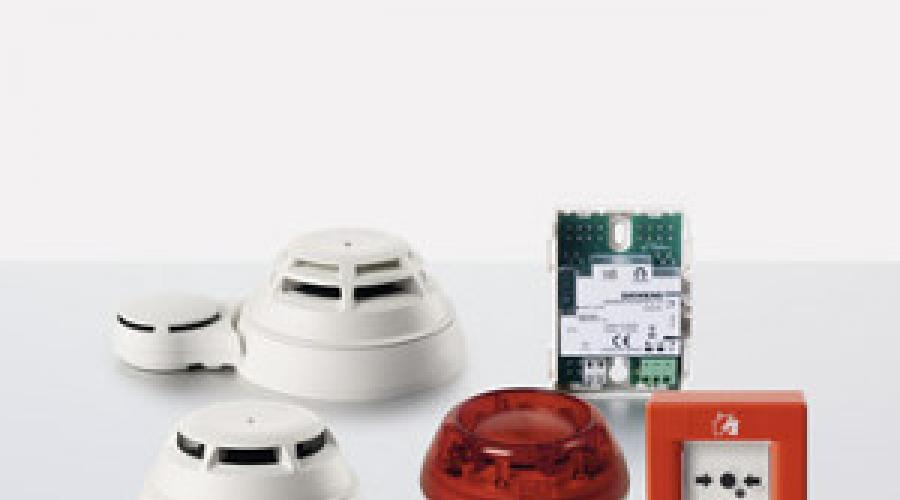
Fire detectors and detectors
Sensors control the physical parameters of the environment. Smoke, heat, combined, manual, light and ionization detectors are used in fire alarm systems.
Distinguish between active and passive detectors depending on the way the signal is generated.
Active detectors form a signal, by changing which (usually this is the change in the controlled parameter), a decision is made to issue an alarm signal.
Passive detectors are triggered when exposed to external factors - temperature changes, the appearance of smoke and other factors indicating a fire.
Fire alarm control and receiving equipment
This equipment feeds the detectors and sensors via the facility's fire alarm loops, receives alarm signals from peripheral devices, and, after analyzing the signals, generates an alarm warning and activation signals for fire fighting systems. For large facilities the alarm signal is transmitted to the central control point of the facility or to the fire departments.
Peripherals
These are devices (with the exception of detectors) that are connected to the receiving and control equipment by external communication lines.
Peripheral devices can perform various functions: control alarm devices from a specific location of the object; ensure the operability of alarm systems; control and manage both conventional detectors and external devices, perform sound and light notification, print alarm and service notifications.
Fire alarm schemes
 When choosing a fire alarm scheme, a number of factors are usually taken into account: the size of the object, the degree of fire hazard of this object, the possible damage from the fire, the estimated cost of the fire alarm system.
The least reliable and effective is the threshold alarm system.. But its low cost makes it possible to use it on small objects with an insignificant degree of fire hazard.
Block in 50% from the beginning of the article article
To build such circuits on Bolid equipment, the Signal-20P, Signal-20M, Signal-10 and S2000-4 control panels are used. Alarm loops include detectors of three types, there is a function for setting additional parameters. The inclusion of the controller-panel "S2000M" in the system expands the functions of the system.
More reliable is the choice of an addressable fire alarm system. This will allow you to install a smaller number of detectors, choose a free line configuration, and also refuse external optical signaling devices. But it is worth considering that the maintenance of such a system is carried out in a planned manner to prevent possible system failures.
The "Signal -10" control panel used in such schemes allows you to connect loops with addressable and conventional detectors.
The use of an addressable analog system will make it possible to avoid these shortcomings. Its sensors respond to temperature fluctuations, measure the level of smoke in the room. Monitoring the performance of sensors allows you to service them in case of malfunctions. The system is easy to program, all sensors are connected to a computer. It is the best choice for responsible objects.
The scheme is carried out using the S2000-KDL controller, to which up to 127 addressable devices are connected: detectors, addressable expanders, relay modules.
Block in 75% from the beginning of the article article
Schemes for constructing various fire alarm systems on equipment manufactured by Bolid are shown in the figure.
Advantages of the Bolid system
Bolid equipment is used to build fire alarm circuits at many large industrial and civil construction projects. The quality of the product is also evidenced by the fact that it is this equipment was used at the Sochi Olympics. The company's equipment can be used to fully implement fire protection schemes for the most complex objects.
The choice of the structural diagram of the ship's fire alarm system is due to the requirement for the number of sensors used (at least 2000) and the need to improve the reliability of the system using double redundancy. As a prototype, we will take the fire alarm system "Photon-A". The prototype has an information network architecture, so we will accept a similar architecture for the designed system with double redundancy.
Redundancy is a method of increasing the reliability of an object by introducing additional elements and functionality in excess of the minimum required for the normal performance of the specified functions by the object.
When introducing redundancy, the concepts of the main element and the reserve element are considered. The main element is an element of the main physical structure of the object, which is necessary for the normal performance of the object of its tasks; a backup element is an element designed to ensure the operability of an object in the event of a failure of the main element.
Reservation multiplicity is the ratio of the number of reserve elements to the number of reserved elements of the object.
Consider the redundancy methods:
- 1) structural redundancy - a method of improving the reliability of an object, involving the use of redundant elements included in the physical structure of the object;
- 2) temporary redundancy - a method of improving the reliability of the object, which involves the use of excess time allocated for tasks;
- 3) information redundancy - a method of increasing the reliability of an object, involving the use of redundant information in excess of the minimum necessary to complete tasks;
- 4) functional redundancy - a method of increasing the reliability of an object, involving the use of the ability of elements to perform additional functions instead of the main ones or along with them;
- 5) load redundancy - a method of increasing the reliability of an object, involving the use of the ability of its elements to perceive additional loads in excess of normal;
- 6) general reservation - reservation, in which the object as a whole is reserved;
- 1) separate reservation - reservation, in which individual elements of the object or their groups are reserved;
- 8) sliding redundancy - redundancy by replacement, in which a group of main elements is backed up by one or several reserve elements, each of which can replace any failed main element in this group;
- 9) a loaded reserve is a reserve element that is in the same mode as the main one;
- 10) light reserve - a reserve element that is in a less loaded mode than the main one;
- 11) unloaded reserve - a reserve element that practically does not carry loads;
- 12) recoverable reserve - a reserve element, the performance of which, in case of failure, is subject to restoration during the operation of the facility;
- 13) non-recoverable reserve - a reserve element, the performance of which, in the event of a failure, cannot be restored under the considered conditions of the operation of the object.
- 14) duplication - redundancy, in which one main element is given one backup;
Let's choose the most acceptable method of redundancy of functional devices in the fire alarm system;
Let's refuse temporary and informational reservation, since these methods require additional time costs and complication of the system software. An increase in time costs leads to an increase in the time of fire detection, which, in accordance with the requirements for shipboard fire alarm systems, is unacceptable. The complication of software increases the requirements for the performance of microprocessor systems, that is, their complexity and, accordingly, the cost.
Therefore, structural redundancy must be used.
We exclude load redundancy, since there are no powerful components in the developed system.
Duplication and common redundancy lead to an increase in the cost of the SPS, but may lead to the desired result. Therefore, in the future, we will consider the possibility of using such redundancy methods.
Let's abandon sliding redundancy, since such a method will lead to software complexity and system cost increase due to the use of complex microprocessor structures.
The most advantageous redundancy method in our case is functional redundancy, since due to circuit solutions, it is possible to ensure both the performance of the tasks by the backup elements and, if necessary, the tasks of the main element, with minimal costs for introducing additional devices into the SPS circuit.
Figure 1.5 shows the scheme of the SPS, built on the basis of the block diagram of the SPS "Photon-A". This block diagram provides for separate double redundancy with redundancy of sensor controllers. Sensors are connected to the loop.
Figure 1.5 - Unit cell of fire alarm peripheral equipment
Figure 1.5 shows a block diagram of a fire alarm system with double redundancy. As in the case of the prototype, the system is a multi-level distributed microprocessor system.
The central unit analyzes the fire situation on the ship, displays information about the state of the fire situation on the indicator display, generates alarms and control signals for fire extinguishing systems and fire door control systems.
The controllers interrogate the sensors, on the basis of the received data they generate signals about the state of the fire situation and transmit them to the central unit, transmit control signals from the central unit to the sensors.
Peripheral equipment has a network architecture and consists of elementary cells similar to devices, the block diagram of which is shown in Figure 1.5
In case of failure of the controller No. 1, a group of sensors D1.1-D1.n can be polled through the circuit controller No. 3 - sensors D1.1-D1.n. If controller No. 3 fails simultaneously with controller No. 1, then the polling of the same sensors can be carried out using controller No. 2. Thus, a device built according to the considered block diagram has increased reliability, compared with a device built according to the block diagram shown in Figure 1.4.
Let's take the block diagram shown in Figure 1.5 as a block diagram of the ship's fire alarm system being developed.
The history of the development of burglar alarms is much longer than is commonly believed. Examples are the ancient designs of original inventions, such as the Japanese "singing floor", the "ear of Dionysius" from ancient Greece, or the Egyptian hidden traps designed to secure the treasures of the pharaohs. The first prototypes of modern burglar alarms began to be developed along with the advent of photocells and electric bells.
Modern technologies provide an opportunity to choose a burglar alarm among many different options. In such systems, a variety of types and combinations of equipment are used. However, in this variety there is a common logic, in connection with which it is possible to describe a common simple burglar alarm, which allows you to get a certain idea of \u200b\u200bits design and principles of operation.
The equipment diagram of any security alarm system includes the following components.
Intrusion detectors. Different types of detectors can be used depending on the project. The most common options are infrared (passive or active), photoelectric, magnetic contact, as well as detectors that respond to sound, glass breaking or temperature changes.
Controller. This is a key component of the security alarm, collecting and analyzing signals from all the detectors of the system, as well as initiating its operation when strangers enter the protected area. At the same time, the controller displays information about the incident on the display or other data display device.
executive device. With the help of this element, the system reacts to violation of the security circuit. Modern alarms are equipped with a wide variety of actuators, including sound (sirens, bells, loudspeakers), communication (announcing an alarm via radio or cellular), visual (light panels, flashing beacons) or active, for example, blocking exits and elevators.
Power supplies and communication lines. These elements are used for power supply (including autonomous) and communication between elements of the security system.
A typical burglar alarm scheme is as follows.
Active infrared motion detectors and passive magnetic reed switches are used as detectors, which trigger the system when the doors are opened. Actuating devices are sound and visual (light) indicators (flashing lamp, siren). The control panel contains security alarm control components, LED indicators signaling in the background the integrity of the circuit, as well as a special relay that starts the mechanisms of actuators when the contacts are closed on it. The system is powered by a 12-volt uninterruptible power supply. As a rule, burglar alarms have an autonomous power supply, since dependence on the central network increases their vulnerability to intruders.
Having a general idea of the principle of construction and operation of a security alarm system, this scheme can be modified and refined using various methods, for example:
- increasing the number of circuits of security systems that are independent of each other;
- combining different types of detectors and optimizing their localization. At the same time, the main task is to eliminate "blind zones" and provide backup scenarios for the operation of the security circuit;
- providing for additional levels of security, such as backup power supplies for the alarm, or methods for quickly restoring the functionality of the security system in case of violation of communication channels;
- integrating the burglar alarm with other security systems such as video surveillance, patrol services, fire fighting equipment, etc.
- supplementing the functions with active security means that affect violators. Paralyzing gas released into the room through ventilation ducts, floor hatches leading directly to the pool with piranhas and other tricks from adventure films are extreme examples of such mechanisms. However, security measures that are not so exotic and dangerous, but similar in principle of action, are often used in reality.
In the absolute majority of cases, measures that complicate the security system are aimed at increasing its reliability and ability to withstand any known methods of stealth penetration or direct intrusion into the protected area. Violators, in turn, are trying to develop effective, fast and discreet ways to bypass all degrees of protection.
In any case, this is another variant of the confrontation between the means of attack and defense, in which each of the parties must constantly develop in order not to give advantage to the enemy. For this reason, new technologies and innovative equipment will be constantly developed in the field of creating burglar alarms in the future. However, the concept of security systems will remain unchanged.
UNITEST specializes in the manufacture of security and fire-fighting equipment, as well as the design of security systems.
The fire alarm scheme, developed taking into account the architectural features of the building, will allow the most rational and efficient arrangement of equipment for the timely identification and localization of the source of fire. The fire alarm circuit should include a fire extinguishing system, building ventilation control, and possibly voice alarm and elevator control.
The burglar alarm scheme is used to develop a system to prevent illegal entry into the building by unauthorized persons. The signaling scheme takes into account the cable laying paths, the installation of sensors, the control panel and the placement of the control system. It is important that the placement of the system minimizes damage to the interior of the building. This factor should also be taken into account in the diagram.
The burglar and fire alarm scheme is designed to take into account the location of the integrated security system. It reflects signaling devices, fire extinguishing devices, control units, as well as the location of the access office and video surveillance systems. The scheme is developed taking into account the individual characteristics of the protected object - the required number of sensors and devices for powder, gas or water fire extinguishing is calculated.
The UNITEST company is an indispensable assistant in the development of security and fire alarm systems. All products are certified and designed to serve your safety.
After we have decided on the type of detectors and the organization of zones, we can draw up an AUPS scheme. When developing the structure of the AFPS, one should take into account the decisions of the Global Fire Equipment company, whose equipment is used on the operating territory of the plant.
The block diagram reflects the composition of the fire alarm system - devices, detectors and connections between them. All workshops of the plant are equipped with fire alarm systems. Linear smoke detectors (IPDL) are installed in each protected room, which protect the main areas of the workshops. In small rooms and places where the use of IPDL is not possible, point smoke detectors (address) are used. On the evacuation routes, on the walls, manual fire detectors are installed.
Processing of information about the state of fire detectors is carried out by the local fire alarm panel (LP). The LP provides for the connection of up to three addressable loops (AL). Addressable detectors (point smoke and manual) are connected to the loop directly, and IPDL and actuators through the addressable detector status controller (CSI). In our case, the actuating devices are: sound sirens equipped with strobe flashes, relays for controlling dampers of fire extinguishing and smoke removal systems. All devices included in the LP loop regularly exchange information about their status with it (Fig. 2.6.).
The detector status controller is designed to control addressless devices through a resistive-loaded loop between them, and transmit notifications to the LP, as well as control actuators. Communication protocols between the modules and the local panel are determined by the equipment manufacturer. From this comes an important requirement - communication protocols must be compatible.
The head unit of the fire alarm system is the central control panel (CCP) located at the checkpoint. Local panels are combined into a network, with a topology - a ring, where the CCU collects information about the state of each workshop (Fig. 2.7.). Communication between the control equipment is provided by means of optical interface modules connected to each LP and MCC. In the event of an alarm, all decisions are made by the central panel, according to the specified work algorithms. However, each LP controls up to 3 analog fire loops with its own independent processor and, in the event of a fault message in the central panel, is able to act independently, giving FIRE / FAULT signals and activating its own sounders and relays. The difference between these modes of operation is that in the event of a communication break, the LP will be able to control only the workshop in which it is located. Warning and control systems for fire extinguishing equipment in neighboring workshops will not be available.
The communication protocol between the central and local panel is determined by the equipment manufacturer, as well as the interface. These issues will be discussed in more detail in the third section of the project.
In addition, the project provides for the installation of a redundant device (network repeater) in each workshop of the plant, which fully reproduces information from the CCU with all control functions, which allows increasing the number of jobs in the system. Information about the status of the entire system is displayed on the LCD display in each workshop and control room. Also, the project provides for the use of a graphical interface that provides communication between the MCU and the operator's PC. Each panel is displayed on the monitor as if the operator were standing in front of it, and can be fully controlled from the computer. In the event of an alarm or malfunction, the location of the event is displayed on the computer screen. There are three zoom levels available to the operator. An individual device can be considered, requested and, if necessary, disabled.
Rice. 2.6

Fig.2.7
Algorithm of work when fixing a fire.
The local panel regularly polls the status of network elements. If a fire is detected by one of the detectors, it sends an event message and the value of the monitored parameter to the MCC via the LP. The MCU generates a “pre-alarm” signal. Information about the event and its location is displayed on its display, monitor and in each workshop. sound signaling devices in the security room. If no response from the operator on duty is received within a predetermined time, the MCC can automatically initiate the formation of commands to control the engineering equipment of other systems (for example, automatic voice notification, smoke removal, unlocking locks on evacuation routes). For this purpose, loop control modules with built-in relays are used for switching "low-current" circuits up to 30 V.
This makes it impossible to determine a specific fire point. Consider the operation of a fire alarm using the example of the Bolid system, one of the most popular on the Russian market. Alarm loops include detectors of three types, there is a function for setting additional parameters. All this could have been avoided if the burned room had been equipped with a fire alarm. The "Signal -10" control panel used in such schemes allows you to connect loops with addressable and conventional detectors. Part of the equipment. When choosing a fire alarm scheme, a number of factors are usually taken into account: the size of the object, the degree of fire risk of this object, the possible damage from a fire, the estimated cost of a fire alarm system. System types.
fire alarm bolide block diagram
This will allow you to install a smaller number of detectors, choose a free line configuration, and also refuse external optical signaling devices. Threshold, or non-address. Passive detectors are triggered when exposed to external factors - temperature changes, the appearance of smoke and other factors indicating a fire. Peripherals. Fire alarm system Bolid. Active detectors form a signal, by changing which (usually this is the change in the controlled parameter), a decision is made to issue an alarm signal. Fire alarm control and receiving equipment.
But it is worth considering that the maintenance of such a system is carried out in a planned manner to prevent possible system failures. At large facilities, the alarm signal is transmitted to the central facility control point or to fire departments. Bolid systems are distinguished by a minimum number of false positives. The quality of the products is also evidenced by the fact that this particular equipment was used at the Sochi Olympics. The company's equipment can be used to fully implement fire protection schemes for the most complex objects. Fire alarm Bolid - a set of equipment that allows you to: establish the fact of fire, transmit an alarm, automatically turn on fire extinguishing and smoke removal equipment, turn off ventilation, turn off power supply (except for special equipment), turn on equipment and equipment that prevent the spread of fire and facilitate evacuation. The panel reflects the number of the “beam” containing the triggered sensor, forming a general alarm signal. Address. This equipment feeds the detectors and sensors via the facility's fire alarm loops, receives alarm signals from peripheral devices, and, after analyzing the signals, generates an alarm warning and activation signals for fire fighting systems.
But this system lacks efficiency: a fire can be detected with a significant delay in time. There are three types of fire alarm systems, depending on the method of detecting a fire that has occurred and the method of transmitting signals about it. Distinguish between active and passive detectors depending on the way the signal is generated. Fire alarm schemes. They are connected to the control panel. The main quality of this system is reliability, which allows minimizing damage in case of fire. This allows not only to detect a fire with the exact localization of the point of ignition, but also to obtain information about the operation of the sensors that make up the system, to quickly eliminate system malfunctions.
fire alarm car
The company's equipment is affordable, easy to expand protection systems, and forms a modular system. Sensors control the physical parameters of the environment. The purpose of the alarm. An important factor is also a good ratio of price and quality of products. Each of us has seen on television the results of fires, which are caused by calling the Ministry of Emergency Situations too late. Smoke, heat, combined, manual, light and ionization detectors are used in fire alarm systems.
The inclusion of the controller-panel "S2000M" in the system expands the functions of the system. Training seminars and webinars are held for the company's clients. Schemes for constructing various fire alarm systems on equipment manufactured by Bolid are shown in the figure. To build such circuits on Bolid equipment, the Signal-20P, Signal-20M, Signal-10 and S2000-4 control panels are used. The scheme is carried out using the S2000-KDL controller, to which up to 127 addressable devices are connected: detectors, addressable expanders, relay modules. During operation, each "beam" transmits signals from 20-30 sensors that are triggered when the threshold value of the controlled parameter is reached.
But its low cost makes it possible to use it on small objects with an insignificant degree of fire hazard. The least reliable and effective is the threshold signaling system. Peripheral devices can perform various functions: control alarm devices from a specific location of the object, ensure the operability of alarm systems, monitor and control both conventional detectors and external devices, provide sound and light notifications, print alarm and service notifications. More reliable is the choice of an addressable fire alarm system. Fire alarm sensors are installed in the controlled room. Advantages of the Bolid system. "Rays" depart from the control panel - fire alarm cables. These are devices (with the exception of detectors) that are connected to the receiving and control equipment by external communication lines.
Fire alarm
And at the end of the video about the installation of the fire alarm system Bolide from the manufacturer. Any fire alarm system used at the object of observation consists of blocks: Detectors and fire alarm sensors. Bolid equipment is used to build fire alarm circuits at many large industrial and civil construction projects. The company provides extensive technical support to its customers in the design, installation and implementation of its products. The control panel generates a request cyclically and receives signals from the sensors about the absence or presence of a fire, about the state of the sensor itself.